|
|
Post by danlank on Jun 12, 2019 13:28:40 GMT
I had a ride behind it a year or so ago, front window in the front coach - and there were one or two moments where I was a bit worried about the bounce! Still, I’m sure the SVR wouldn’t do anything unsafe...
|
|
|
|
Post by Roger on Jun 12, 2019 20:10:10 GMT
This is a piece of Silver Steel being made into a punch to make the gaskets I'm fitting to the inside of the tank filler lids. I'd already made one before, but it was just a bit too big and the gaskets won't fit. I adjusted the model and had another go. This is 2D machined for the most part then 3D machined to get the chamfer to the cutting edge.  20190611_113110 20190611_113110 by Anne Froud, on Flickr The hole in the middle is to locate a punch for the centre hole. I'm hardening it so the edge doesn't get damaged. I've fluxed it so it doesn't end up black and horrible.  20190611_115315 20190611_115315 by Anne Froud, on Flickr There's always a bit of oxide, but not too much. Here it's cleaned up and being tempered.  20190611_121006 20190611_121006 by Anne Froud, on Flickr A little squeeze in the vice is all it takes to cut out the gasket.  20190611_122618 20190611_122618 by Anne Froud, on Flickr 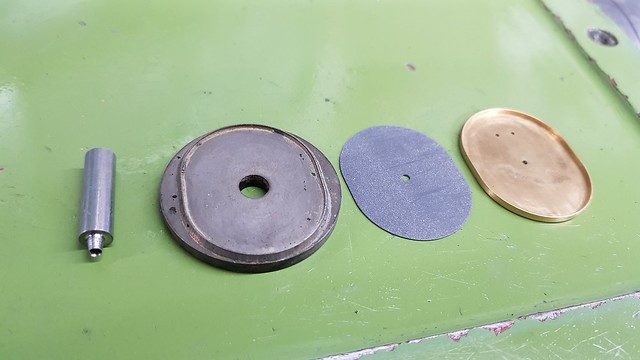 20190611_122909 20190611_122909 by Anne Froud, on Flickr The inside of the gasket needs a bit of support since it's pretty thin. This is a 0.5mm thick Brass retaining washer that has an M2 hole in the middle. If you try to turn this and part it off, it ends up dished and scrapped. The solution is to use the parting tool first and leave a stub of about 4mm diameter to hold the end while the end is turned flat and the hole drilled and tapped. Then it's just a matter of taking a couple of cuts on the back with the parting tool to get the right thickness before parting it right off. 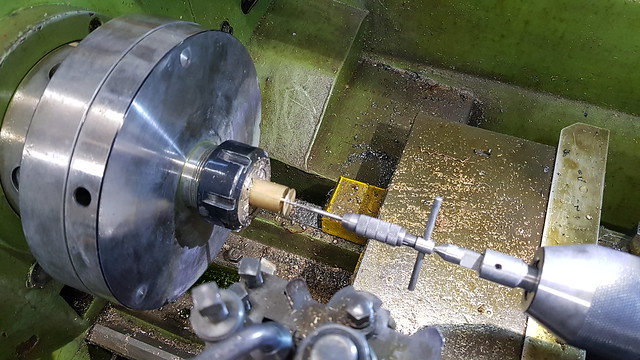 20190611_222302 20190611_222302 by Anne Froud, on Flickr The tiny bush is Phosphor Bronze and has an M2 thread on the outside to match the Brass retainer. The hole in all of these parts is 2mm which is way too big for the leaf spring that holds the lid down. The leaf spring has a 1mm hole in it so the little pin has a 1mm shank that goes into the bush. That mean I can retain a scale appearance and functionally it's the same as the real thing. The 1mm pin will be retained with a drop of Loctite when it's finally assembled after painting. 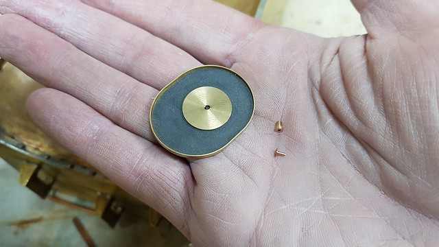 20190612_195130 20190612_195130 by Anne Froud, on Flickr The loop that stops the lid revolving is 1.6mm diameter Stainless Steel wire which has been cut to length and here it's getting a tiny bit of peening over so it doesn't come out. 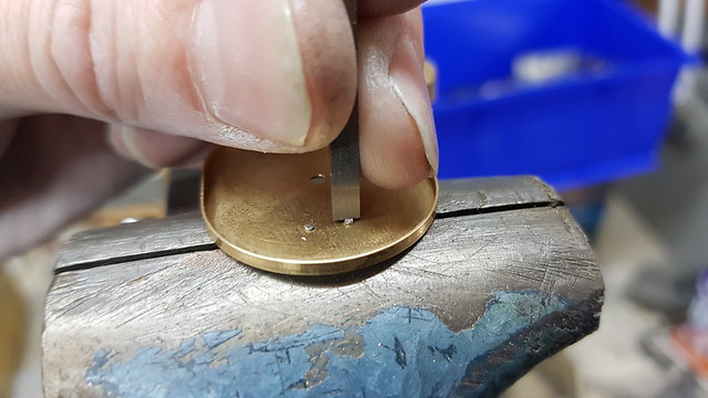 20190612_200610 20190612_200610 by Anne Froud, on Flickr I'm using some of the 96S Tin/Silver Eutectic Solder that Jim Scott kindly gave me at the Doncaster show. I've shaved off two miniscule scraps of Solcer and also used a little liquid flux that's also formulated for Stainless Steel.  20190612_201417 20190612_201417 by Anne Froud, on Flickr Although this looks fine... 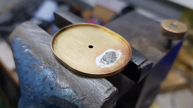 20190612_201737 20190612_201737 by Anne Froud, on Flickr ... only one of them really penetrated...  20190612_201953 20190612_201953 by Anne Froud, on Flickr ... so here I've very carefully scraped the root of the joint with a scalpel to get the oxide off... 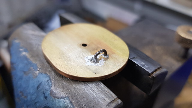 20190612_203126 20190612_203126 by Anne Froud, on Flickr ... and that did the trick.  20190612_203955 20190612_203955 by Anne Froud, on Flickr This is the result, albeit waiting for the pivot pin details to be sorted out. The latch works a treat, with the Phosphor Bronze leaf spring compressing the lid in place and holding the clamping lever horizontally which is how it's shown on the Works Drawings.  20190612_204413 20190612_204413 by Anne Froud, on Flickr I've left the Solder on the underside to the loop since it's not seen and it doesn't interfere with the operation.  20190612_204436 20190612_204436 by Anne Froud, on Flickr Time to make the other one now I know this is going to work. |
|
JonL
Elder Statesman
 WWSME (Wiltshire)
Posts: 2,912
|
Post by JonL on Jun 12, 2019 20:48:00 GMT
Very elegant Roger.
|
|
|
|
Post by David on Jun 13, 2019 4:25:26 GMT
Clearly this one doesn't fit... That gives heart to the rest of us! I saw on the prototype photo some pretty obvious welds in the sharp corners of the firebox angle so at least that doesn't have to be a perfect soldered join. Amazing work as always. I must have missed a lot because I saw something about an anti-roll bar. That will be a first on a small loco. |
|
|
|
Post by Roger on Jun 13, 2019 9:10:12 GMT
Clearly this one doesn't fit... That gives heart to the rest of us! I saw on the prototype photo some pretty obvious welds in the sharp corners of the firebox angle so at least that doesn't have to be a perfect soldered join. Amazing work as always. I must have missed a lot because I saw something about an anti-roll bar. That will be a first on a small loco. Hi David, Mistakes are just as common in my workshop as in anyone else's, it's just part of the process and nothing to worry about or be ashamed of. I don't know if I've shown this before, but here's a first draft of one Anti-Roll bar arrangement that's feasible. I had to get at least this far in the design so that I could add any holes to stretchers or frames before that became impossible to modify. I've added fixing holes for dampers to the frames and holes in the pump stretcher for an attachment point for an Anti-Roll bar. So the idea on this prototype was to introduce a pair of new bearings that fit over the axle in two halves, along the lines of an eccentric. It might be possible to connect the ends of the bars directly to the axle boxes, but it's not easy to do that without putting an offset load on them. That might be what I end up doing though. Having them separate does mean it's easy to experiment with and the movement is accommodated by the bearings moving on the axle. As it stands, the 'U' shaped Spring Steel rod is 4mm diameter. That's a complete guess, and possibly on the large side, but until it's made I won't be able to tell. For those not familiar with this sort of thing, they're used on road vehicles to allow vertical movement of both wheels on an axle (or independent suspension) at the same time, but they resist any difference in height because that would require the twisting of the torsion bar. It's a really simple idea, but massively decreases body roll, and in the case of a locomotive it ought to reduce the waddling tendency.  Anti-roll bar Anti-roll bar by Anne Froud, on Flickr Anyway, I think it's interesting and something new to play about with. |
|
|
|
Post by ettingtonliam on Jun 13, 2019 10:10:38 GMT
It will be interesting to see how well that works. It doesn't do anything for the end to end pitching or nosing though, does it, and that seemed quite pronounced on the film. Possibly the 1500 class tanks with their short wheelbase just weren't intend for speed. To quote Harold Holcroft
'---It has 8 in piston valves with outside Walschaerts gear, the object being to give facilities for oiling from the ground, an advantage in busy shunting yards for which the class was intended. The wheelbase was short, only 12 ft 10 in. so that.sharp curves of 3ch radius could be taken at slow speed, but the large overhang resulting at each end made the engine unsuitable for running at any but very moderate speed.---'
|
|
|
|
Post by Roger on Jun 13, 2019 12:04:15 GMT
It will be interesting to see how well that works. It doesn't do anything for the end to end pitching or nosing though, does it, and that seemed quite pronounced on the film. Possibly the 1500 class tanks with their short wheelbase just weren't intend for speed. To quote Harold Holcroft '---It has 8 in piston valves with outside Walschaerts gear, the object being to give facilities for oiling from the ground, an advantage in busy shunting yards for which the class was intended. The wheelbase was short, only 12 ft 10 in. so that.sharp curves of 3ch radius could be taken at slow speed, but the large overhang resulting at each end made the engine unsuitable for running at any but very moderate speed.---' Absolutely right about end to end pitching, and it doesn't address damping issues from side to side either. I'm exploring damping options, and even got as far as modelling something but it's still early days for that. The main thing was to get a handle on where any attachment points for dampers would need to be and to get those on the frames while it's still possible. I can only damp the front two axles though, there's not enough room to do anything at the rear. Still, I think any damping would be better than none, and two axles damped ought to have some effect on the pitching. I have looked at dampers used in Radio Controlled Cars, but concluded that they don't really fit very well. The problem with designing dampers is that you have to account for the change in volume if you have a single ended damper. Usually that's done by having a free floating piston at the closed end. One thought is to just have a through shaft that means the volume doesn't change. Ok, that does entail two seals, but it might prove to be the simplest solution. It's a really interesting problem, and one that doesn't appear to have been investigated on Miniature Locomotives to me knowledge. I know the purists won't approve of any of these devices, but they're hidden away so personally I don't think they're offensive. I'm really surprised that damping wasn't fitted to locomotives, when even the earliest road vehicles had them. I know the surfaces they ran on were different, but the same issues are present and well understood in both. I would imagine it's pretty scary to run at high speed in an undamped locomotive. |
|
|
|
Post by terrier060 on Jun 13, 2019 12:54:09 GMT
Hi Roger
I have been stuck out here in Bermuda with temps high 70s low 80s for nearly three weeks and now have a few hours left before the flight home, so have had great enjoyment reading your thread and some of the others, when I have had time. The anti-roll bar issue got me reading back through your thread to the discussion on balancing wheel weights and there was a long discussion which got very complicated and brought Bill Perrett's Speedy into question. I have to stick up for Bill here, because yes his engine did rock slightly as you pulled away under full power, and the springing was relatively soft which gave it the good grip. I may be wrong, but I think you may have seen the loco running recently ( by that I mean not when it was in the care of Bill). The loco had not been cared for or regularly serviced after Bill's death and the springing was one of the major items that needed attention. I think Barry Eden and Merlin Biddlecombe did their best to look after the engine and I was chatting to Merlin at Barry's funeral. A very sad occasion. I gather the loco has been sold and hope that it has landed in good hands and we shall soon see it running again.
Ed
|
|
|
|
Post by Roger on Jun 13, 2019 13:10:33 GMT
Hi Roger I have been stuck out here in Bermuda with temps high 70s low 80s for nearly three weeks and now have a few hours left before the flight home, so have had great enjoyment reading your thread and some of the others, when I have had time. The anti-roll bar issue got me reading back through your thread to the discussion on balancing wheel weights and there was a long discussion which got very complicated and brought Bill Perrett's Speedy into question. I have to stick up for Bill here, because yes his engine did rock slightly as you pulled away under full power, and the springing was relatively soft which gave it the good grip. I may be wrong, but I think you may have seen the loco running recently ( by that I mean not when it was in the care of Bill). The loco had not been cared for or regularly serviced after Bill's death and the springing was one of the major items that needed attention. I think Barry Eden and Merlin Biddlecombe did their best to look after the engine and I was chatting to Merlin at Barry's funeral. A very sad occasion. I gather the loco has been sold and hope that it has landed in good hands and we shall soon see it running again. Ed Hi Ed, I'm climbing the walls to get back home if I'm away for more than a week, so I feel your pain. We have what's called 'full throttle' holidays where we don't stop long enough to get bored, so that makes them palatable. I'd still rather be at home though. I can't comment on what, if any, differences Bill Perrett's SPEEDY has received by way of springing, only on what I saw on the day. Soft springing is definitely the way to get more grip, but that introduces all of the issues we're discussing, at least on some level. As it stands, I'd say it's currently so soft as to be dangerous, but that's just a personal opinion. |
|
|
|
Post by terrier060 on Jun 13, 2019 15:20:44 GMT
Yes Roger, it was never like that in Bill's day and I used to drive it most weekends. I can only remember it once derailing and that was because someone put something on the track on the far bend. It felt quite safe to drive and we used to go down the straight at some speed.
Merlin did say the springs were bad and they were going to stiffen them. Why they should have gone soft I can't imagine. It is quite a top-heavy loco even in full size.
In the long run one can theorise as much as one likes, but it's the practical test that counts.
|
|
|
|
Post by Roger on Jun 13, 2019 15:49:35 GMT
Yes Roger, it was never like that in Bill's day and I used to drive it most weekends. I can only remember it once derailing and that was because someone put something on the track on the far bend. It felt quite safe to drive and we used to go down the straight at some speed. Merlin did say the springs were bad and they were going to stiffen them. Why they should have gone soft I can't imagine. It is quite a top-heavy loco even in full size. In the long run one can theorise as much as one likes, but it's the practical test that counts. Hi Ed, That sounds very different to how it was in the days you drove it. I don't know how springs can change like that, it seems more likely that someone else has changed it. I agree completely that it's the practical test that counts. With a top heavy locomotive there's more to be gained through experimentation, and I'm looking forward to that. Lots of locomotives 'waddle' and that's one thing I'd like to address because I'm sure mine will do that if the springing is soft. Watch this space! |
|
|
|
Post by Deleted on Jun 13, 2019 16:07:25 GMT
Interesting discussion on dampers etc, I'm sure there's a good reason that they weren't used in full size but if really wanting some form of suspension within a set of locomotive frames I think that I would be looking at a 'torsion bar' setup. It works for main battle tanks at high speed and some of those are just as heavy as a tank loco, work very well on my car too...  Pete |
|
|
|
Post by chris vine on Jun 13, 2019 16:44:39 GMT
Hi Roger,
Re anti roll bars: It doesn't matter if the loco rolls a bit. however what will be a disaster is if the anti roll bar resists a wheel on one side dropping into a dip in the rail. It only takes a little lift of the wheel to have it off the track.
If you really want an anti roll bar, perhaps you could fit it to the centre axle only. Then, if it does cause a wheel to not drop into a dip, the leading and trailing wheels sets should keep you out of the flower bed...
Chris.
|
|
|
|
Post by Roger on Jun 13, 2019 16:51:56 GMT
Interesting discussion on dampers etc, I'm sure there's a good reason that they weren't used in full size but if really wanting some form of suspension within a set of locomotive frames I think that I would be looking at a 'torsion bar' setup. It works for main battle tanks at high speed and some of those are just as heavy as a tank loco, work very well on my car too... Pete Hi Pete, I suspect dampers weren't used simply because they could get away without fitting them, even if the ride was scary at high speed. I guess most locomotives never went that fast, so it would only be express locomotives that might run into trouble if they happened upon a piece of track that reinforced the oscillation. I'm sure you won't find a diesel or electric locomotive without dampers, and presumably those aren't as top heavy as Steam Locomotives. Maybe the leaf springs add just enough damping to be able to cope with the worst of the conditions Steam Locomotives encounter. I wonder what the Health and Safety people made of all this when they were certifying Tornado for use on the main line. Maybe they have 'Grandfather rights'? |
|
|
|
Post by ettingtonliam on Jun 13, 2019 20:45:39 GMT
Interesting discussion on dampers etc, I'm sure there's a good reason that they weren't used in full size but if really wanting some form of suspension within a set of locomotive frames I think that I would be looking at a 'torsion bar' setup. It works for main battle tanks at high speed and some of those are just as heavy as a tank loco, work very well on my car too... Pete Hi Pete, I suspect dampers weren't used simply because they could get away without fitting them, even if the ride was scary at high speed. I guess most locomotives never went that fast, so it would only be express locomotives that might run into trouble if they happened upon a piece of track that reinforced the oscillation. Precisely the point with the Southern's River class tanks and the Sevenoaks(??) disaster in the 1920s. They rode fine on decent track but tended to bounce off at speed on less good track. |
|
JonL
Elder Statesman
WWSME (Wiltshire)
Posts: 2,912
|
Post by JonL on Jun 13, 2019 21:02:52 GMT
An extra lug on the centre of the anti roll bars could link the first and last axles to create anti-pitch bars....
|
|
|
|
Post by andyhigham on Jun 13, 2019 21:27:54 GMT
If you are worried about pitching spring/damper units could be fitted between front and rear axle boxes so that when the front is compressed it exerts a force extending the rear thus keeping the loco level
|
|
jma1009
Elder Statesman
Posts: 5,901
|
Post by jma1009 on Jun 13, 2019 22:03:18 GMT
To my mind, the obvious solution to a 'bouncy' Speedy is to fit proper leaf springs rather than coiled springs. Leaf springs are far superior in their characteristics, and also prototypical.
Coiled springs are very difficult to get right and adjust, and easily 'bottom' out, and have a tendency to oscillate on short wheel bases.
I have never quite understood why Bill Perrett's 'Speedy' bounced about as it is a heavy loco, and if it had light springs these would have bottomed out. If it had stiff coil springs it would not have bounced about, but would have presumably slipped quite a bit.
Cheers,
Julian
|
|
|
|
Post by terrier060 on Jun 13, 2019 22:05:06 GMT
With your knowledge of electronics Roger, how about an active suspension? That really would be novel!
|
|
|
|
Post by Roger on Jun 13, 2019 22:05:51 GMT
Interesting ideas about anti-pitching, there's no reason why some sort of device like the anti-roll bar couldn't be devised. I'm not sure if any solution is going to involve the rear axle though, the firebox completely surrounds the rear horn blocks, so there's no way to attach anything to the axle box as far as I can see. That doesn't mean that the front two axles can't attempt to control this to some degree. I need some kind of spanner to remove the Test Cocks on the inside of the cab, something that grips more than just a short length. I think a normal spanner will make nasty marks on the hex. So this is going to be a special spanner for that purpose. It's made from Mild Steel since the forces shouldn't be that large. I printed one out first to make sure it felt like it was going to be the right shape and size. Here I'm drilling out the corners of the Hex pocket with a 0.6mm diameter drill x 6mm deep. 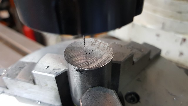 20190613_122829 20190613_122829 by Anne Froud, on Flickr Then it was profiled with a 3mm cutter, 0.5mm at a time...  20190613_142305 20190613_142305 by Anne Froud, on Flickr .. leaving this. Here I'm using a 1mm 2-flute PCB cutter so the flutes are long enough to reach. I'm taking 0.05mm cuts, 2 thou in old money. 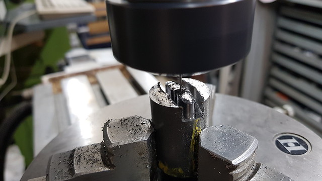 20190613_143443 20190613_143443 by Anne Froud, on Flickr 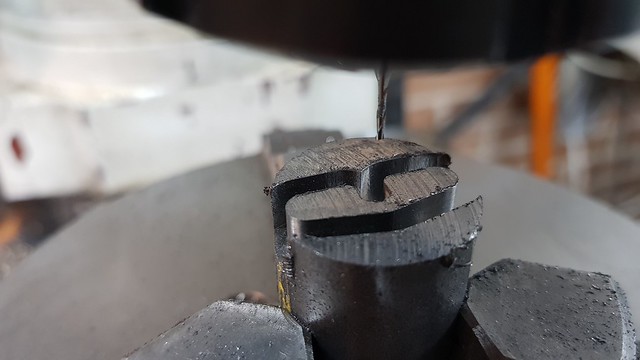 20190613_175516 20190613_175516 by Anne Froud, on Flickr 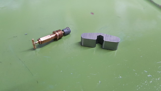 20190613_181807 20190613_181807 by Anne Froud, on Flickr The idea is that it can turn round and miss the adjacent cock. 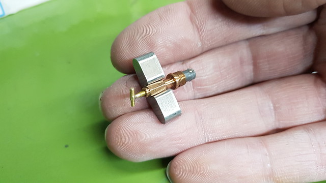 20190613_181918 20190613_181918 by Anne Froud, on Flickr The fillers have a boss on either side of the pivot bracket at the rear...  IMG_1416 IMG_1416 by Roger Froud, on Flickr ... and this is a piece of 1.6mm Titanium welding wire being ground down to 1.2mm so I can use it to hold the parts while I Solder them. You can't solder Titanium because of the Oxide it forms on the surface which won't be removed by the flux.  20190613_215129 20190613_215129 by Anne Froud, on Flickr I've rested a couple of curved scraps of 60/40 Solder on the joint and added a blob of Plumber's waxy flux...  20190613_220456 20190613_220456 by Anne Froud, on Flickr ... which worked a treat on one but not the other because the Solder fell off. The second time it worked on that one too. I warmed the whole thing up with a flame to help stop too much heat being sucked away into the tank body. What I forgot was that I'd left the Water Level Gauge parts in there! Doh! Fortunately there was no harm done, it obviously didn't get hot enough to cause a problem.  20190613_221101 20190613_221101 by Anne Froud, on Flickr The second one was done in the same way... 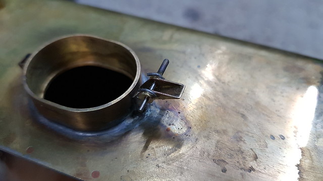 20190613_222316 20190613_222316 by Anne Froud, on Flickr ... but the first attempt didn't bridge the joint, and all the Solder ended up on the bush... grrrr. I re-fluxed it and added a tiny scrap of Solder across the top of the joint to bridge the two parts, and this was the result.  20190613_222741 20190613_222741 by Anne Froud, on Flickr The Titanium wire pulls out by hand, there's no adhesion to that at all. |
|


