dscott
Elder Statesman

Posts: 2,438
|
Post by dscott on Dec 11, 2019 0:38:03 GMT
Can you start a list of advanced purchases please.
Doug Hewson put together a Book of Wagon Building and we chatted about signed copies when we met up 2 years ago at the Midland show.
I seem to put articles in our Club Magazine and then get a mention in Model Engineer in the Club notes quite often... And they even did a photo of my Battery drill driver powered Loco!!! Yes with a bucket of rubble on board, she pulls 4 adults. And is held together with M6 Bolts!!! 4 circuits of the Oxford track per battery.
My collection of 1500 bits grew last weekend with some Big Prairie Tank castings that are spare but bought in a collection. Gunmetal horns and complete axleboxes and brakeshaft bearings.
David ad Lily, in for the cold weather with the sitting room currently resembling Barry Scrapyard.
|
|
|
|
Post by jon38r80 on Dec 11, 2019 22:04:55 GMT
What is the finish on the real Durbar plate floor on the full size loco, black paint or galvanised? Perhaps these plates are an opportunity to try nickel plating if the real ones are galvanised. If the surface finish of the Durbar plate isn't too smooth it will look pretty much like galvanising. My experience
E of it is external access ways and stairs in industrial plants and always had it made galvanised, sometimes powder coating over the galv if it needed to be pretty.
|
|
|
|
Post by Roger on Dec 11, 2019 22:29:17 GMT
What is the finish on the real Durbar plate floor on the full size loco, black paint or galvanised? Perhaps these plates are an opportunity to try nickel plating if the real ones are galvanised. If the surface finish of the Durbar plate isn't too smooth it will look pretty much like galvanising. My experience E of it is external access ways and stairs in industrial plants and always had it made galvanised, sometimes powder coating over the galv if it needed to be pretty. The chequer plate is black painted, so the intention is to just Black them using my Blacking kit. |
|
|
|
Post by Roger on Dec 11, 2019 22:39:38 GMT
I've been doing more modelling on the cab to see how the roof needs to be so it's still possible to drive it. The top has this fixed vent arrangement at the front, and there's room to model that and still be able to see the turret. The chains for the whistles are attached to guide tubes that are behind that, but I don't think I can have them both as they are on 1501 because there may not be room. On 1501, there's a second sliding vent in the roof, I suppose the roof could come back a little further towards where that starts. I don't what it to be a nuisance reaching the reverser when it's fully forward though. I've driven locomotives where the controls are hard to reach and it's not much fun. So you can see the cutout I've made in the RH side of the bunker shelf so it's easier to get the shovel into the firehole. I'll make that part of the shelf detachable, it can be secured with magnets so I've got the option to run with or without it. I've also modelled the gutter which I've attached to the RH side only for the moment. I'll probably use a few rivets to hold those in place. The sides need to be attached on their edges to the roof, so I'll use the TIG welder to tack them on the inside. I'll probably Silver Solder the joint, and that might include the gutter too, we'll see. 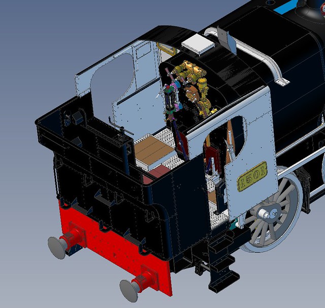 Cab driving arrangement Cab driving arrangement by Timothy Froud, on Flickr |
|
|
|
Post by Roger on Dec 12, 2019 22:04:33 GMT
The cab sides were originally made as one piece, with a Vee groove on the outside to give the appearance of it being joined. Now that I've decided to split the cab at this point as per the full size locomotive, I need to cut this instead. That's a problem, because a saw blade is way too wide and it's very tricky to get one of my fine slitting saws in a position where they can be used. In the end, I opted to cut it through almost to the bottom of the Vee on the front with a 0.5mm diameter PCB burr. These are totally unsuitable for this task, they're optimised for FibreGlass and are a diamond pattern instead of a cutting edge used for Steel. However, they are very hard indeed, so taking things really gently it's just possible to get away with it, albeit with the odd breakage. Here I've clocked up the back edge and I've dropped a drill into one of the bolt holes that's aleady been drilled. The plate on the back was going to be a dummy, but now it's functional, so it needs rivet holes too. Those will be sanded flat because on the real thing it's welded on.  20191211_160730 20191211_160730 by Timothy Froud, on Flickr It's very hard to see when it's aligned perfectly, so I'm using the clock on the side of the drill to see if it deflects when it's offered up to the hole. The same was done in the other axis.  20191212_123409 20191212_123409 by Timothy Froud, on Flickr With the holes drilled, the slow process of cutting the slot began. I ended up using 24,000RPM and 5mm/min with a 0.05mm cut. I managed to break four cutters on the first one before finding the sweet spot and the second one was done without breakage.  20191212_121235 20191212_121235 by Timothy Froud, on Flickr  20191212_161250 20191212_161250 by Timothy Froud, on Flickr There was only a wafer hloding the parts together when it was finished, so I can tidy that up and it won't look any different. 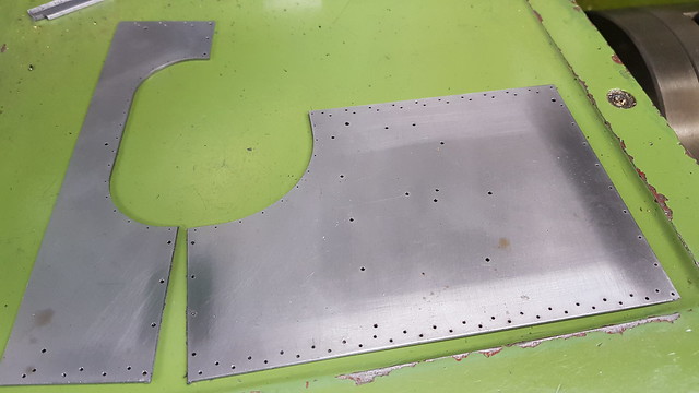 20191212_214549 20191212_214549 by Timothy Froud, on Flickr This is the cab roof I modelled yesterday, it's got four small holes around the vent hole to locate the pillars that support the top. As before, there are two rows of rivet holes. One for the dummy rivets which are closer to the edge, and the structural ones that will be filed flush. The thickness of the material both on the spectacle plate and the angle bring the scale position of the rivets on the edge of the inner angle which is no good. You either have to accept that they have to be further from the edge than scale or use scale thickness material. The look on the inside is plausible because the structural rivets are visible in the right place on the angle. The outside ones look right because they're the right distance from the edge. As always, it's a compromise.  20191212_212019 20191212_212019 by Timothy Froud, on Flickr |
|
|
|
Post by Roger on Dec 15, 2019 17:09:50 GMT
I've spent a few days sorting out some of the detail design points of the Cab, as well as creating the tool paths and such like. This is a piece of 1.2mm Steel Plate being turned into the lower halves of the Spectacle plate. 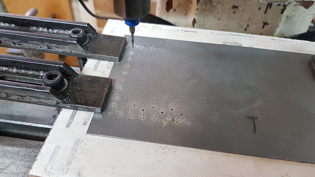 20191214_105012 20191214_105012 by Timothy Froud, on Flickr The high speed spindle is ideal for this sort of work, but I've not used it much in the past because it didn't reach down low enough. Now I've resolved that deficiency and also added spindle control from Mach4, it's much more useful. I've settled on 2.5mm cutters for this kind of work. That's because they're at the lowest price for any size of cutter. In other words, cutters smaller or larger are more expensive.  20191214_121838 20191214_121838 by Timothy Froud, on Flickr  20191214_142157 20191214_142157 by Timothy Froud, on Flickr You can see that I can now use the high speed spindle while leaving the EasyChange adaptor in the R8 taper of the main spindle. I've added a changeover switch on the side of the control cabinet that allows the control signals to be directed either to the VFD of the main spindle or the one controlling the high speed one. A 6 way Audio DIN type lead connects the control to the high speed spindle VFD so it can be quickly disconnected. There's also a changeover switch on the high speed spindle to allow that to be run manually when it's used on the grinder. When you have so little space, lots of things have to perform more than one task to justify their place in the workshop! I've taped up the top half of the Spectacle plate here because I made a mistake by leaving only two tabs and I didn't want it to break free on this finishing cut. I moved the clamps one by one as it went round too, so they clamped the inside too, just for good measure. It's easy to find that some of the tabs have been almost lost if the sheet lifts slightly.  20191214_183219 20191214_183219 by Timothy Froud, on Flickr Anyway, it's been a productive few days with a complete set of parts for the basic shape. I now need to make the angles to hold it all together and form the bends at the top before beginning the assembly.  20191215_111424 20191215_111424 by Timothy Froud, on Flickr |
|
|
|
Post by Deleted on Dec 15, 2019 17:13:49 GMT
Nice work Roger... looks great...  Pete |
|
|
|
Post by Roger on Dec 16, 2019 21:38:53 GMT
These are going to be the angle iron corners for the sides of the cab to the spectacle plate. They're made from 0.6mm Steel sheet. I've ground up a robust 90 degree engraving tool which was run down the middle twice to get a finished depth of 0.35mm The outsides were machined with a 2.5mm end mill at 20mm/min using the high speed spindle.  20191216_101612 20191216_101612 by Timothy Froud, on Flickr After cleaning up, those were folded and then adjusted manually to get them to be exactly 90 degrees...  20191216_113723 20191216_113723 by Timothy Froud, on Flickr .. which looked like this. 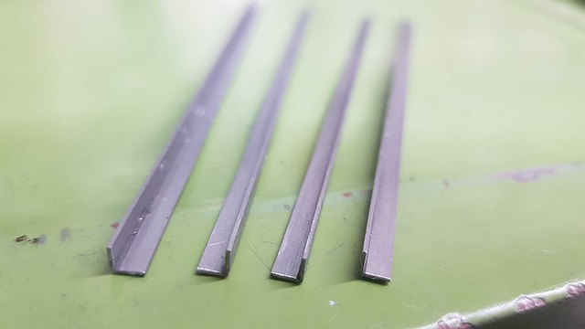 20191216_195024 20191216_195024 by Timothy Froud, on Flickr I drowned each one in flux and cut small pieces of Silver Solder to place at intervals along the join. The Titanium welding wire support was bent to provide a Vee shape to hold them.  20191216_195458 20191216_195458 by Timothy Froud, on Flickr Once it had all melted, I ran the point of another Titanium welding rod down the joint to even out the Silver Solder. 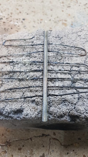 20191216_195848 20191216_195848 by Timothy Froud, on Flickr This is how they looked after 20 minutes in the ultrasonic tank... 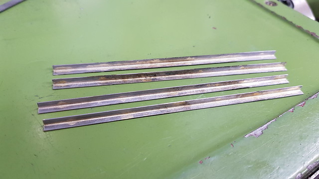 20191216_210453 20191216_210453 by Timothy Froud, on Flickr ... only one of the backs is a little oxidised. 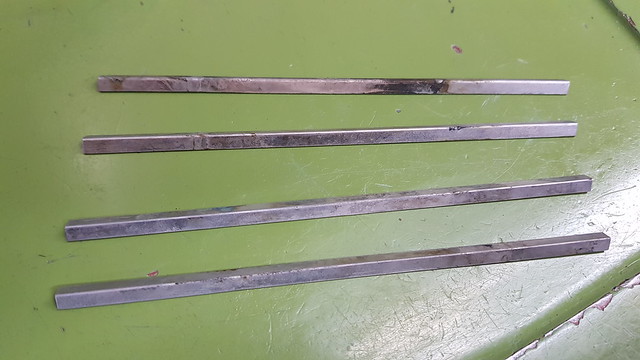 20191216_210511 20191216_210511 by Timothy Froud, on Flickr Cleaning up and running a small round needle file along the groove, they looked like this. 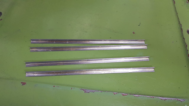 20191216_212819 20191216_212819 by Timothy Froud, on Flickr |
|
mbrown
Elder Statesman
Posts: 1,723
|
Post by mbrown on Dec 16, 2019 22:26:48 GMT
Brilliant work Roger! My new project requires loads of small angle and brass just looks wrong, so I was wondering how to make them in steel.
Amy chance you could show a picture of your 90 degree engraving tool? If you ground it up yourself, maybe I could make one too.
Malcolm
|
|
|
|
Post by Roger on Dec 16, 2019 22:41:09 GMT
Brilliant work Roger! My new project requires loads of small angle and brass just looks wrong, so I was wondering how to make them in steel. Amy chance you could show a picture of your 90 degree engraving tool? If you ground it up yourself, maybe I could make one too. Malcolm Hi Malcolm, I'll try to remember to do that tomorrow. It's basically a 'D' bit ie a 90 degree ground point with a flat across the centre line. I then carefully backed off the trailing edge by hand, adding relief back to the cutting edge. It wasn't that pretty, but it was good enough. It's pretty hard on the tool, so you may need to sharpen it a couple of times. I'd make it from a HSS drill blank rather than hardened Silver Steel which I don't think would last very long. It certainly makes for a surprisingly strong angle even though it's thin. |
|
dscott
Elder Statesman
Posts: 2,438
|
Post by dscott on Dec 17, 2019 0:30:15 GMT
I use old steel legs from office tables or failing that B & Q square tube as they do some fine stuff if you have not got a bender.
Set the mill to cut the angles to final size once cut and one side deburred. Hold in a ling vice and keep moving along.
I have a new lot to make now.
For a sharper outside edge use thicker section and mill the outer sides followed by draw filing and sanding.
Going the whole Nine Yards file the inside edges rounded!
David and Lily.
|
|
|
|
Post by steamer5 on Dec 17, 2019 2:36:18 GMT
Hi Roger,
Inspiring stuff as usual!
I’m still waiting for the 2nd price for my stretchers to come back from the water cut guy, 1st was $600 + plus the GST, government theft. The financial controller wasn’t impressed!
So after discussion I’ve adjusted the drawings to reduce the square corners to 0.5 mm radi which the guy tells me means the jet doesn’t stop at so speeds thing up....time on the table costs! I’m looking at soldering the sides on which means castellated main plates & slots in the returns.
Anyway I checked out the cost of silver solder....BLOODY HELL! $65 for 2 x1.5 sticks locally! I’ve gotta find a cheaper source! Or open a silver mine.
Cheers Kerrin
|
|
|
|
Post by Roger on Dec 17, 2019 8:06:20 GMT
Hi Roger, Inspiring stuff as usual! I’m still waiting for the 2nd price for my stretchers to come back from the water cut guy, 1st was $600 + plus the GST, government theft. The financial controller wasn’t impressed! So after discussion I’ve adjusted the drawings to reduce the square corners to 0.5 mm radi which the guy tells me means the jet doesn’t stop at so speeds thing up....time on the table costs! I’m looking at soldering the sides on which means castellated main plates & slots in the returns. Anyway I checked out the cost of silver solder....BLOODY HELL! $65 for 2 x1.5 sticks locally! I’ve gotta find a cheaper source! Or open a silver mine. Cheers Kerrin Hi Kerrin, With that sort of price for water jet cutting, you could soon buy a CNC machine and do it yourself! Have you tried eBay or Amazon for the Silver Solder? Failing that, I expect a UK company could ship to you since the weight won't be that great. |
|
|
|
Post by steamer5 on Dec 17, 2019 8:29:11 GMT
Hi Roger,
Now there’s an idea!
Yes I’ve checked out eBay, & yes it looks like a cheeper option, depending on the % silver, then there’s buying a gas set........& on it goes!
To be fair it’s is a fair few parts.....25 in 3 mm, 24 in 4 mm, 3 in 5 mm & 1 in 6 mm. It did include all the holes & supply the material. In total 31 of those are side or top returns with slots on average of 20 x either 3 or 4 mm.....so quite a bit of table time.
Then there is the rear engine with just as many AGAIN,
I’m thinking I my just going buying some 16mm plate & start carving! Then make a visit to the scrap man with a bucket of swarf.
Cheers Kerrin
|
|
|
|
Post by Roger on Dec 17, 2019 20:39:41 GMT
This is the 90 degree engraving tool used to cut the groove in the plates I'm making into angles.  20191217_110038 20191217_110038 by Timothy Froud, on Flickr The cab roof has a an angle piece welded above the cab opening to direct the water away. It's only 2.5mm angle when scaled, so it's pretty small. The angle is bent at the apex so it's lower at the front and back.  P9268749 P9268749 by Roger Froud, on Flickr Somewhere in amongst these burrs are the two plates that will become those angles.  20191217_154754 20191217_154754 by Timothy Froud, on Flickr This is how they look when cleaned up, wiped down with Methylated Spirits and folded....  20191217_192849 20191217_192849 by Timothy Froud, on Flickr ... and this is how they look when Silver Soldered. Now I need to add a few rivet holes to hold them in place before bending them into shape. 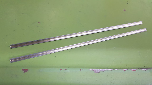 20191217_202837 20191217_202837 by Timothy Froud, on Flickr |
|
|
|
Post by Roger on Dec 18, 2019 22:56:47 GMT
These are the 0.85mm holes for the rivets that will hold these gutters in place. I'll bend them in the middle shortly so they're ready for fitting.  20191218_113851 20191218_113851 by Timothy Froud, on Flickr And this is how they look at the moment. They're pretty small, only 2.5mm across.  20191218_204346 20191218_204346 by Timothy Froud, on Flickr Moving on, this is the angle piece that attaches the top of the Spectacle plate to the Cab roof. The cutouts are to miss the window frames. I toyed with several different ways of making this, from making straight angle and forming the shape, making the two parts from sheet and using tabs to hold them for Silver Soldering, to making it from solid.  Cab roof angle Cab roof angle by Timothy Froud, on Flickr To be honest, it's a real faff to make these the hard way, so I decided to just machine it from solid. So here's a piece of 5mm Cold Rolled bar being annealed ready for machining.  20191218_115912 20191218_115912 by Timothy Froud, on Flickr  20191218_163718 20191218_163718 by Timothy Froud, on Flickr I'm using the high speed spindle for all of this since the profile will be done with a 2.5mm cutter and it will be slightly quicker. I can still use the 5.5mm cutters I've got plenty of for the roughing out. Here I've faced off the top of the part to bring it down to the right thickess over the vertical angle. The line across the middle was just a test to see if the height was set right. There's a lot of scale on this side, I only cleaned up the bottom.  20191218_163754 20191218_163754 by Timothy Froud, on Flickr The 5.5mm cutter roughed out the inside, leaving 0.5mm so that I could use a 3mm radius mill with a 0.5mm corner radius to get the internal fillet.  20191218_192109 20191218_192109 by Timothy Froud, on Flickr  20191218_201052 20191218_201052 by Timothy Froud, on Flickr The profile is well on the way to being finished, but it will have to run on into the night to get that done. Fortunately it's whisper quiet, so I'll just let it finish, lights out. |
|
|
|
Post by Roger on Dec 19, 2019 10:53:47 GMT
|
|
|
|
Post by Roger on Dec 20, 2019 22:18:10 GMT
I popped a few rivets through the holes to check it all lined up and fitted the window for good measure. All seems ok, and the hing on the window looks like it's just going to touch the firebox cladding. I was actually expecting to require a cutout for that, but it might not be necessary. We'll see. You can see the Spectacle plate has been bolted to the bottom pieces with M1 nuts and bolts. I bought some Stainless Cheese head screws for that since you won't see the back of them. I might Loctite those in place. The nuts and plates need to come off so that the top part can slide upwards. I need to make sure the nuts come off the screws, hence the Loctite. None of these things will be done up that tightly.  20191219_215820 20191219_215820 by Timothy Froud, on Flickr Anyway, after much messing about, I've got the Spectacle plate lined up correctly and here I'm spotting through all of the rivet holes.  20191220_192835 20191220_192835 by Timothy Froud, on Flickr Moving on to the Cab sides, the top has a curve where it meets the roof. That's going to need careful bending since the start of the bend needs to be the right distance from the bottom of the Cab. It also needs to be the right radius. To that end, here's a piece of tooling being made for the Sheet Metal Folder I made all that time ago. It's the first piece I've made like this. The other bends I've needed were much larger radii, so I used a roller type of tooling. Anyway, this is it roughing the shape and a wobbly video of that too. This is using a 2-flute 10mm Carbide Slot drill 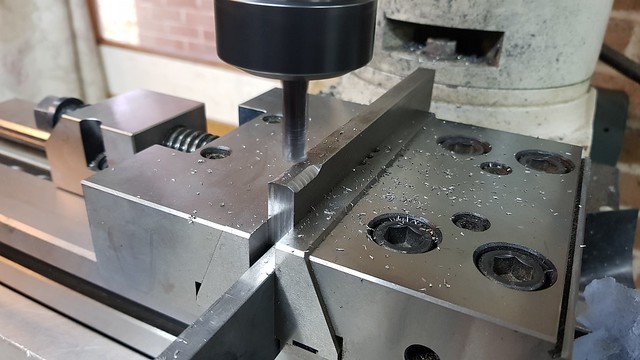 20191210_095030 20191210_095030 by Timothy Froud, on Flickr And this is a wobbly video of the 10mm Carbide Ball nosed cutter finishing off.  20191210_101857 20191210_101857 by Timothy Froud, on Flickr The radius isn't symmetrical, that's intentional. I've created a parametric model whereby I can change the radius required and the stock size and it creates all of the tool paths. I imagined I'd be making more of these!  20191210_121316 20191210_121316 by Timothy Froud, on Flickr It's held on by a series of M6 x 10 Cap Screws and located with 3mm dowels. 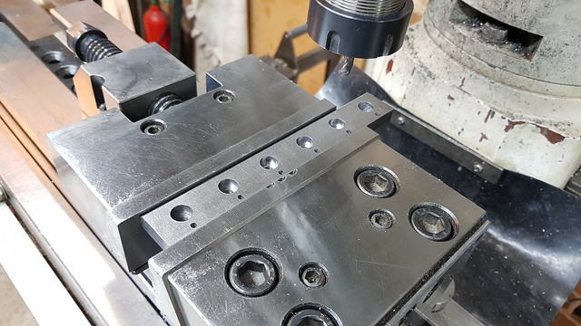 20191210_144457 20191210_144457 by Timothy Froud, on Flickr This is how it looks on the folder. I've only done a piece long enough for the job in hand. I can make another one if I ever need to fold something bigger.  20191220_215605 20191220_215605 by Timothy Froud, on Flickr This is all set up ready to go. The folder pivot point has been raised to be at the centre of the radius and the folding bar dropped to suit.  20191220_215615 20191220_215615 by Timothy Froud, on Flickr I just need to cut a trial piece that's the same length as the Cab side and check that I've got the setting distance right before I bend the real thing. |
|
|
|
Post by Roger on Dec 21, 2019 22:58:15 GMT
I bent a test piece in the folder which sprang back more than I accounted for, so here I'm tightening up the radius on the forming tool for the bender. Setting the height is best done from a definite known point, such as the top of this dowel.  20191221_105110 20191221_105110 by Timothy Froud, on Flickr There wasn't too much to come off, so I went straight to a finishing pass with the 10mm Ball nosed cutter. 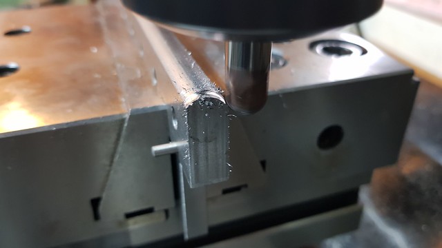 20191221_110222 20191221_110222 by Timothy Froud, on Flickr I don't know if I've shown this before, but the pivot point on my folder can be raised and lowered to fold any radius.  20191221_110351 20191221_110351 by Timothy Froud, on Flickr 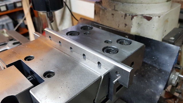 20191221_144453 20191221_144453 by Timothy Froud, on Flickr This time it came out better...  20191221_151115 20191221_151115 by Timothy Froud, on Flickr  20191221_152411 20191221_152411 by Timothy Froud, on Flickr But the folder isn't stiff enough to get the bend as tight as it should be... 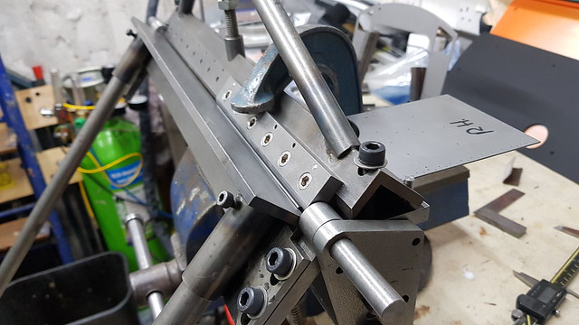 20191221_154241 20191221_154241 by Timothy Froud, on Flickr 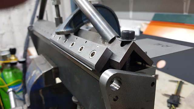 20191221_155909 20191221_155909 by Timothy Froud, on Flickr ... so I used the planishing hammer to finish the job,  20191221_160325 20191221_160325 by Timothy Froud, on Flickr This side came out very well...  20191221_160504 20191221_160504 by Timothy Froud, on Flickr  20191221_160540 20191221_160540 by Timothy Froud, on Flickr  20191221_162546 20191221_162546 by Timothy Froud, on Flickr ... but this side ended up a bit bruised on the front edge. The rest of the fit is fine, so I'll live that and fill the corner if needs be when I get the roof attached and I can see how it looks. I'm not going to stress over that, sheet metal work can be fickle.  20191221_213652 20191221_213652 by Timothy Froud, on Flickr The cab roof was easily bent using the rollers...  20191221_215603 20191221_215603 by Timothy Froud, on Flickr ... but before I can fit that, I need to attach the sides and get the corner angles drilled. The cab roof was made a little wider than the exact size required to give a bit of wriggle room if this sort of problem arose. It's very difficult to get a bend to start and end precisely where if should. 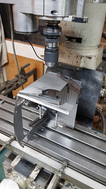 20191221_221835 20191221_221835 by Timothy Froud, on Flickr |
|
|
|
Post by Roger on Dec 22, 2019 19:58:56 GMT
Nothing very exciting to show today, just a steady plodding along adding all of the holes to the two front angles on the front RH corner of the Cab.  20191222_143551 20191222_143551 by Timothy Froud, on Flickr Fortunately, I've got a comprehensive collection of Toolmaker's clamps, some bought, some home made. I've managed to mislay the second really long reach one which is a pity. I bought quite a few smaller ones at the Great Dorset Steam Fair this year. They were a bit beaten up and bent, with some of the threads being a bit mangled. However, with a bit of attention they were all made serviceable. 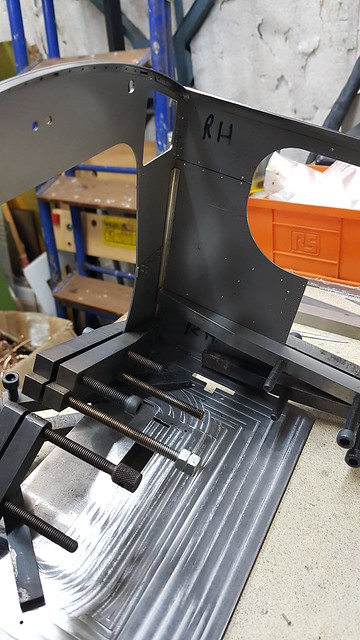 20191222_143601 20191222_143601 by Timothy Froud, on Flickr The Silver long reach Toolmaker's clamp on the top is the especially useful one I mentioned.  20191222_144734 20191222_144734 by Timothy Froud, on Flickr Clamps, clamps and more clamps. I've dropped rivets into some of the holes already drilled to make sure it doesn't move.  20191222_171156 20191222_171156 by Timothy Froud, on Flickr Holding the assmebly in the machine vice proved to be a handy way to do it. The clamp on the far bottom right and small parallel are to support the hanging edge of the Cab side so I could press down with the drill without it bending away.  20191222_190359 20191222_190359 by Timothy Froud, on Flickr The 3x4x6 block helped stop it wobbling about like a jelly. 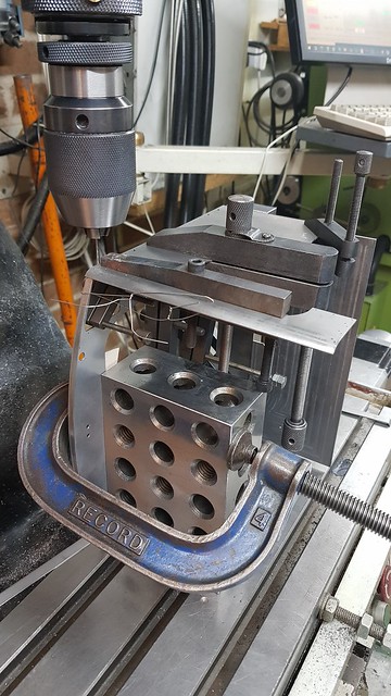 20191222_193509 20191222_193509 by Timothy Froud, on Flickr So, not much to show for a lot of time spent, but it's necessary to guarantee that it all ended up square and true. I'll probably clean this up and attach the angles permanently so I don't end up losing what piece goes where. It will also make it a bit more rigid when I come to do the other corner. |
|


