|
|
Post by Roger on Apr 11, 2015 8:51:20 GMT
Hi Roger, it's a static edge finder, this one is mine but we use them at work too. It works on completing an electrical circuit on contact. I have a brand new 20mm R8 collet that I use only for this edge finder, and last time I checked the runout there wasn't any. We use similar ones at work, we never bother about it. You could if you were worried about it find the edge, then roatate the spindle 180 degrees and find it again Thanks for that Ed. I use the drill chuck to hold the edge finder and that's not good enough to use one of those. I think I ought to get another easychange adaptor and use it solely for the sort of edge finder that you have. I have done that 180 degree procedure when using a round bar when I couldn't use the wobbler but it's not that convenient. |
|
|
|
Post by ejparrott on Apr 12, 2015 16:32:10 GMT
Up at sparrowfart this morning..... Holly said she was coming home at 430..... me being me, and seeing as see was flying in all the way from Mexico...thought she meant 0435.....turns out not...it was 1635....wondering why I hadn't had a phonecall I went and looked it up...still heading up towards Newfoundland...... Hey ho... So having some time spare, I finished drilling through the last 0.5mm that I'd left due to sitting on hard parrallel's, then tapped the two halves of the pump eccentric. It's now bolted together and ready for turning the step on it that locates the strap. It'll probably be a while before that happens but watch this space!  |
|
|
|
Post by ejparrott on Apr 26, 2015 16:12:34 GMT
I've spent a few hours over the last week and a bit individually fitting the four axleboxes to their respective horns, they all now slide up and down nicely with no rattle. I'm still wondering whether I need to increase the tilt allowance at all to allow for track irregularities. Yesterday afternoon I spent a couple of hours at work and I've finished the turning and boring so they're tantalisingly close to going on the axles and the engine being wheeled now. I left 4 thou on the back faces so that any marks from the various machining ops would likely be machined out so that still needs to come off when I get the surface grinder working again, and I need to drill the oilways from the reservoirs down to the bores, but that's all.    I've also had a session silver soldering and reduced the pile a bit, I've fitted the brass slipper plates to the boiler expansion brackets, assembled the handbrake crank, and built up the crossheads... 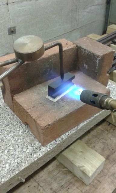  That little lot should give us a bit to be getting on with. We've finally bought our own shot blast cabinet at work, one of my jobs in the very near future is to get electric and air to it, once I've done that I'll be able to get the bits of soldering blasted and cleaned up. We've also moved our surface grinder, and I need to re-level that and run a new electric supply to it, then I can flash the backs of the axleboxes and they'll be ready for fitting. I've also got hour long cuts on my machine so I can do some hand work while that's running. I'm going to get on with the expansion brackets so I can get them fitted to the frames, along with the two footplate/bunker support brackets on each side, one of which is another job waiting for fabrication. Believe it or not, the engine isn't even on it's wheels yet and I've used over half of my photobucket allowance! Looks like I might now need to open a Flickr account for it too! |
|
|
|
Post by Roger on Apr 26, 2015 17:19:35 GMT
Lovely job Ed, and huge progress. I really like that arrangement you have for holding things down when Silver Soldering, I may have to contrive something like that myself.
|
|
|
|
Post by ejparrott on Apr 27, 2015 8:12:43 GMT
Just a third hand, made up from bits of scrap. Usually use it when I'm welding but does occasionally help with these jobs that don't have any mechanical fixing
|
|
|
|
Post by Deleted on Apr 28, 2015 9:26:54 GMT
Hi Ed ,
I've been following your build thread for a while and have been particularly interested in the methods you use to make some of the machined components .
Keeps reminding me of a conundrum though :
Hacking out big bits of metal for pay is toil - hacking out big bits of metal for nothing is enjoyment !
Regards ,
Michael .
|
|
|
|
Post by ejparrott on Apr 28, 2015 9:49:42 GMT
Yes, and some of these bits are getting big!
|
|
|
|
Post by vulcanbomber on Apr 28, 2015 18:11:50 GMT
Nah, making huge amounts of swarf is fun, pay or no pay......
|
|
|
|
Post by ejparrott on May 8, 2015 16:23:28 GMT
Progress is still slow and nowhere near as much as I'd like, but I have done a few more bits this week. With the photobucket account getting filled rather rapidly, I've backed off a little on the photo uploading :naughty: Having recommissioned the surface grinder at work and having hour long cuts on my machine, I have now flashed the 4 thou off the back thrust faces...just the feed holes from the oil reservoirs down to the axles to do and then fingers crossed it's time to fit them and drop the wheelsets into the frames s_clap I've also been progressing a pair of brackets which support the bunkers at the back, and have the stepped bits of footplating bolted to them. I previously profiled the main angles, which I've beefed up a little, just to give a bit of extra in-case strength...probably totally unnecessary! The real bracket is a bit of a mystery, not sure if one of the quarries have got at it as it looks similar to that on the drawing, but not the same....I wonder if years of water and coal dust running down did for it. That one is a folding from 1/2" steel plate. I've built mine up from the afore mentioned profiles plus 2mm steel plate, silver soldered together. No laser cutting of this bits of plates either, I marked out and cut them on the band-saw I'll have you know! I've left excess material on the edges, and I'll trim them to size now they've been stuck together. I'll get these done up as soon as, then they and the bits of footplating can be shot blast and painted and it'll be another bit to bolt on to the frames.  |
|
|
|
Post by arch1947 on May 9, 2015 7:52:05 GMT
I like the three legged holding widget. Nice idea.
Cheers,
Arch
|
|
|
|
Post by ejparrott on Jun 2, 2015 10:32:36 GMT
How time flies...
I have been making small slow progress, driving axle is now in and propped at it's designed running height, leading axle needed some more adjustment to the thrust faces of the axleboxes so that's not in yet. Should be okay now but I just haven't got around to fitting it. I've made it's props at the same time as making the driving axle ones so it's ready to go otherwise. I need to finish off the dummy keeps which have a jacking screw in them to keep it all clamped in the right place, then I can turn the frames back over the right way up again.
Meanwhile it has been odd little bit's here and there. I've machined the bolting holes in the pump eccentric strap so I can finish bore that now and turn the eccentric at the same time, they'll be ready for fitting then. I've also squared up the bit's for the boiler expansion brackets and I can get on and finish machine them now when I get five minutes.
On the cylinder front, a decision has finally been made, and we're going with machining from solid. I had really hoped to experiment with lost foam casting, but the commercial outfits just wanted far too much money for the patterns, and it seems like there aren't enough foundries yet really geared up for doing jobs like this. UCB gave me a price of £37 pounds each for 250 grade iron, and at that I couldn't really say no! All being well they'll be on order today, along with the larger piece of iron I need for the valve eccentric straps which are bigger than the pump and which I'd completely forgotten about.
|
|
|
|
Post by ejparrott on Jun 2, 2015 20:42:31 GMT
The iron has been ordered!  |
|
|
|
Post by Roger on Jun 2, 2015 20:47:26 GMT
I'm sure you won't regret that decision. You'll get better material quality and that's an amazing price too. It's well worth the trouble of carving pieces out of solid for those reasons in my opinion.
|
|
|
|
Post by ejparrott on Jun 3, 2015 8:17:17 GMT
The issue was the sheer size of them, at 8 1/32" long on the bolting flange. Yes I can do it on the Bridgeport, when it's up and running, but it'd take an immense amount of time. I've had a very generous offer to plunge mill the profile on a much tougher bed mill, and that's what makes it worth pursuing.
|
|
|
|
Post by ejparrott on Jun 5, 2015 13:35:59 GMT
I'm hot, and bothered, and tired, so I'm calling that wheeled....  Still need to finish the dummy hornkeeps with the jacking bolts in so I can turn it over, and still need to dress the ends of the keys and paint the axle ends and axleboxes, but I'm calling it! |
|
foote
Active Member

Posts: 16 
|
Post by foote on Jun 13, 2015 14:42:05 GMT
Ed, could you have a separate bolted on bolting flange to keep the size of the CI block down a bit? I can't remember whether that is possible with the cylinder arrangement on your loco. That's certainly what I did on the MWB loco, but that has outside valve gear etc. of course.
|
|
|
|
Post by ejparrott on Jun 13, 2015 14:50:27 GMT
Hi Alain, well..there's no real reason why not, separate bolting flanges have been a feature of many engines through the years, Les Warnett's design for the 9F David is building is one such example. On a personal level though, I didn't want to. Dad refused to conform to the 'norm' and accept flanges couldn't be cast when he did the cylinders for the TR No. 4, my original plan was to follow suit with castings for the MW...albeit somewhat larger1 Even though castings are now not going to happen, it's still a prefernce to me to have the flange integral. And here they are....all 40Kg's of them...each!  The estimate from the CAD was something like 16Kg finished so there will be a lot of swarf, however the machined-from-solid blocks will probably be heavier, as we won't reduce the mass quite so much doing it this way, mostly because of the time and access aspects |
|
foote
Active Member
Posts: 16
|
Post by foote on Jun 13, 2015 17:17:42 GMT
As you say they are big lumps!
|
|
|
|
Post by ejparrott on Jul 30, 2015 10:25:53 GMT
I do keep looking at it and there is still CAD work going on in the background, but I've not much to update. I did however have a suitable piece of material in the machine the other week, so I borrowed some of the excess and made the smokebox door, along with a fixture for finishing it. I've decided to go back to taking photo's regardless and once photobucket is full then I'll go over to Flickr, so Matt will be pleased to see lots of photos!! First up was to machine the outside curve/dome. I was going to do this manually by working to a set of positions in D and Z, then blend together, but the CNC was available so I used that instead. The same CAD data was then used to create a mirror version to use to hold it for finishing....  The female version was then popped on the mill to have a load of holes drilled and tapped for clamping the door inside it. The transferred to the lathe for facing up the back. Left a bit too much metal on really, but our saw occasionally wanders and I didn't want to have to start again. Only the pressure of the tailstock centre is holding the job....  Once I'd faced it to thickness, a simple set of M8 capheads screws and ordinary washers was used to clamp the door back in the fixture - this is after I'd finished it just at the end of my break and had took it out of the lathe, it's on the step to the big lathe.  and there you go....   the hole for the clamp is Ø11.5mm, it'll have a 7/16" shaft with a 5/16" square on it for the dart handle and a 1/4" thread for the clamp handle...maybe 5/16". As you can see...I still haven't finished riveting up the smokebox itself... I'm kind of concentrating efforts on getting my mill up and running at the moment. The lack of milling facilities at my beck and call is rather holding things up now. I've got a number of things that are ready for milling such as the crosshead fabrications and the main eccentrics. I've got one servo motor fitted now, hopefully for the last time. I'm waiting on a new taperlock bush then I can fit the second, then I need to make a mount for the third encoder...it's all progress. Quietly happening in the background also is progress towards milling the cylinder blocks. The material is now in stock for them.... I'm just getting tooling together, and a very generous friend is working with me to mill them out on his HASS bed mill, so keep eyes peeled, they're on the way!! |
|
|
|
Post by GWR 101 on Jul 30, 2015 10:56:41 GMT
Ed, nice looking bit of work, it's certainly going to be a hefty loco. I don't envy you moving it about, I was machining some solid steel 10 1/2" diameter wheels on Tuesday for a 7 1/4" build and lifting them into the lathe was a real strain for an old guy like me, I must be out of condition.  Regards Paul. |
|


 Regards Paul.