pault
Elder Statesman

Posts: 1,496
|
Post by pault on Aug 1, 2014 22:23:28 GMT
They look very nice Julian that little bit of extra work makes something good that bit more special. I did make some scaleish gauge glass fittings which had stainless steel handles on the shut off and blow down valves. Personally I don't find them too hard on the eye but being scale they are quite small. I guess you could TIN coat to get a goldy brassy look
|
|
jma1009
Elder Statesman
Posts: 5,901
|
Post by jma1009 on Aug 2, 2014 8:16:49 GMT
hi roger and paul,
many thanks for your kind comments.
the handles are attached on squares and press fitted on. the squares are a few thou too long and will get a light peening over to stop the handles falling off in service later on when all finished and the spindles have graphite packing soaked in steam oil added.
i made the stainless spindle for the blower valve yesterday evening. thankfully the 1/8" dia austenitic stainless i picked out and which ive had for years from one of the ME suppliers isnt as tough as some stuff ive had. (i probably used 1/8" stainless welding rod on the last batch i made and boy was that tough!) ive you've ever made replacement clock arbours then this kind of job isnt too bad but a very sharp tool is obviously required and correct centre height when turning the stainless down to just over 3/32" dia before threading 1/8" x 40 tpi. i turn the spindle down to dead size of the I.D. of the die when set correctly so that accuracy and concentricity cutting the thread is maintained. the spindle is then fitted into one of the 'double connectors' itself put into the tapped adapter it was drilled and threaded with to again ensure concentricity when turning the cone on the end, finishing off with a fine file.
just the square on the end to file to finish!
you end up with quite a selection of 'adapters' threaded of different sizes for these sort of jobs. the rear of the body of the valves where they screw into the boiler bushes is turned and threaded first, but a word of caution here - dont drill through for the 'seat'. instead turn round and fit into an adapter and centre deeply and drill through from the front of the valve body, open out, and finish with a 5/32" end mill to depth and tap 3/16" x 40. that way all the 'internals' will be concentric.
cheers,
julian
|
|
|
|
Post by Roger on Aug 2, 2014 11:14:08 GMT
Yet more useful notes squirrelled away for later reference, thanks Julian. The threads sound like they might be done in a similar way to the following job if the material is really tough.
I occasionally have to make drawbars for an auto toolchange spindle. These run at 80,000RPM and the concentricity of the collet thread has to be near perfect. It's a 3mm piece of Silver Steel and the M3 thread is 10mm long ending in an undercut. It's a very highly stressed component, the closing force on the collet it huge and it's trying to pull the thread off the end.
For those, I clock it up as good as I can get it, ie, no discernable movement on a 2 micron clock, and add an extra 3mm on the end with the thread to support it using a small half centre. I screw cut the thread with an insert (in the old days we finished them with a die) and then very gingerly tidy up the end with a razor sharp tool to remove the unwanted portion with the centre. It's time consuming but the results are superb. Anyway, it's another way to get round the issue of using tricky materials and fine if you don't want to make a lot of them.
|
|
|
|
Post by ejparrott on Aug 2, 2014 11:52:35 GMT
Could you not get them thread rolled Roger? Much stronger thread as you're not cutting the 'grain' of the steel.
|
|
|
|
Post by Roger on Aug 2, 2014 13:18:31 GMT
Could you not get them thread rolled Roger? Much stronger thread as you're not cutting the 'grain' of the steel. It's not worth it for how infrequent the job is and how many variants there are. It's easy enough to do now I know how to go about it but there were a few failures in the early days, leaving too sharp a radius in the root. Life became much easier with the arrival of tipped threading tools. |
|
jma1009
Elder Statesman
Posts: 5,901
|
Post by jma1009 on Aug 2, 2014 21:08:51 GMT
made the blower valve handle today. making the plain handle and silver soldering in the extension of the handle didnt take too long (all stainless), but trying to file the spokes took ages! quite a bit more work required till im happy with the appearance! as Ben will know ive sort of copied the later valve as currently fitted to Stepney (probably an Ashford valve) rather than the 'original' reproduction valve that BOXHILL has in the NRM. cheers, julian  |
|
jma1009
Elder Statesman
Posts: 5,901
|
Post by jma1009 on Aug 2, 2014 21:54:26 GMT
This is part of the fullsize Stepney's backhead as preserved. i always like to have extension spigots on 'round' handles so i can see at glance what position they are, plus easier to turn. i will have to add the scallops on the outer edge of the 'round' handle at some point when ive finished the spokes. the valve im referring to is lower right. in fullsize this isnt the blower valve, but is 'spot on' where my hollow longitudinal stay is located through the boiler for the blower. a small turret/manifold will go where the whistle cord finishes to supply steam for the whistle valve inside the cab plus steam for the blower and a few other bits. my steam valves for the injectors are on the boiler barrel outside of the cab as per fullsize. don young used a similar arrangement on his FISHBOURNE O2 IW loco, and my great friend Vince Williams did the same on his fabulous SR S15 in 5"g. cheers, julian  |
|
|
|
Post by Roger on Aug 3, 2014 5:51:21 GMT
I like the idea of the handle with a spigot, that makes good sense. I see what you mean about the scollups, that's quite fiddly.
|
|
|
|
Post by Roger on Aug 3, 2014 20:05:27 GMT
Here's the valve on one of the locomotives I saw today, I quite like the look of that. Quite how 'scale' that is I don't know, but it looks easy enough to make. 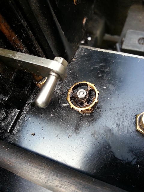 20140803_132500 20140803_132500 by rogerfroud, on Flickr |
|
|
|
Post by gingerneer on Aug 3, 2014 21:42:11 GMT
Hi Julian
How do you get correct size and squareness of the squared ends on the spindles with a file? Do you use a filing rest on the lathe and indexing? Is the square hole the hand wheel broached? The blower with through connection is very neat, that would be ideal for a Hydrostatic lubricator feed. I am looking at the valves for Ayesha and thinking i can do better using this style of valve.
Will
|
|
jma1009
Elder Statesman
Posts: 5,901
|
Post by jma1009 on Aug 3, 2014 23:04:15 GMT
hi will,
the spindle is screwed into a hexagonal adapter (a square one might be more useful!), some washers added so that the file cuts up to the same depth, and then filed in the vice turning the adapter round 90 degrees. after a bit of practice, and judging the shape and size of the filed portion i can do them in a few minutes quite accurately. it is easier to do this if the 'square' is longer than required, then cut back the extra length afterwards.
i dont broach the squares in the handle and would in any event be i think very difficult to do in tough stainless (though would be ok with brass) but i do have some very nice swiss needle files.
this reminds me of a story i have often told of a friend with a light engineering business building a stuart turner triple expansion engine in spare time. he made a spark eroder that took him some time to make just to make the squares in the valve handles! i would have filed them in a few minutes!
including cylinder drain cock levers and regulator handles i must have made well over 100 'squares' this 'method'. squares on regulator rods are done in the 4-jaw with some brass washers added then filed as above turning the chuck.
i appreciate that my method wont suit everybody, and perhaps i am very lucky in always having been quite handy with a file. on a 3/32" dia spindle you can get a square on the end of 68 thou and i can usually get this 'spot on' with just a few checks with a mike. my favourite 'square' needle file is smooth and very sharp even after using on stainless, and is pretty much 1/16" square most of its length so quite similar to using a broach i suppose on these sorts of jobs. i probably have about 100 needle files, half of which have 'white' painted handles for use on non-ferrous stuff.
for the spokes on the handle i really ought to have used my dremel with a dental burr to open out the holes i'd drilled, as filing them to shape is taking ages! the OD of the round part of the handle is only 3/8" OD. i dont often make 'round' handles as all GWR locos had different 'single' handles (roger please note!), and the last ones i made of this type were 9/16" dia for LINDA so much easier to file the spokes!
cheers,
julian
|
|
peteh
Statesman
 Still making mistakes!
Posts: 760
Member is Online
|
Post by peteh on Aug 4, 2014 1:27:00 GMT
Hi Julian - nice tip on the file handles - I must implement a similar system on mine!
|
|
jma1009
Elder Statesman
Posts: 5,901
|
Post by jma1009 on Aug 4, 2014 3:13:42 GMT
very difficult to photograph due to the cab roof, but here's some of the boiler fittings on my 3.5"g Ffestiniog Railway LINDA. stainless round handles on the rear manifold top for the 2 injectors, then below (left) hydrostatic lubricator steam feed, and (right) blower valve with handles that are the same as most of Stepney's in fullsize. vacuum ejector etc far left then sight feed, and FSD pressure gauge. the vacuum gauge is knackered as shows 15 in hg although the loco is 'cold', and needs replacing! cheers, julian  |
|
|
|
Post by Roger on Aug 4, 2014 5:42:35 GMT
Hi Julian,
Duly noted, I'll use the pictures I took of the cab as my reference. As for square shafts and holes, you already know my answer to that problem. The corners of the hole will just need the touch of a file to take out the 0.5mm radius.
|
|
|
|
Post by gingerneer on Aug 4, 2014 8:49:01 GMT
Hi Julian
Thank you for the explanation. I do find myself over complicating processes, thinking a machine must be used. I will go and have a practice and invest in a good set of Swiss needle files. I do have a odd one but not a set, and the idea of have separate ones for ferrous and non ferrous is good. I have a set of larger files set aside for boiler making. Linda's back head looks fantastic.
Will
|
|
|
|
Post by Deleted on Aug 8, 2014 20:51:07 GMT
You are quite right Julian, on full size 55 that valve is the steam heat, wheras on 672 it is the Westinghouse pump steam valve Cheers Ben |
|
jma1009
Elder Statesman
Posts: 5,901
|
Post by jma1009 on Aug 9, 2014 22:20:57 GMT
unfortunately i have managed very little time in the workshop the last few weeks but did manage this afternoon to make a bit more progress on the top water gauge fittings in hard drawn phos bronze. due to my desire to have scale valves on the boiler barrel for the steam injector valves, plus due to the elbows required on such a small boiler for the top water gauge fittings, the top water gauge fittings have an 'offset' of the cleaning plug hole being lower down than the centre of the rear spigot. a small but otherwise complicated problem that hopefully ive overcome. this will provide clearance (i hope) for the steam injector valve spindles which are otherwise in line with the top caps on the top water gauge fittings. quite a bit of work still to do! cheers, julian  |
|
|
|
Post by Roger on Aug 10, 2014 7:17:36 GMT
A lot of work, but worth every minute in my opinion, it looks superb.
|
|
|
|
Post by Deleted on Aug 10, 2014 7:57:50 GMT
Loving this thread Julian... the fittings and backhead look great which for me is a very important part of a model......very nice...  Pete |
|
jma1009
Elder Statesman
Posts: 5,901
|
Post by jma1009 on Aug 10, 2014 9:18:42 GMT
thanks roger and pete, the bottom water gauge fittings are proving a bit of a pain insofar as i cant decide what type of blowdowns to fit and where and whether i will have room for the different types - due to the tray over the fire hole, and the firehole door operating lever. ideally i would like to copy the following  which is from the following thread beginning of the year modeleng.proboards.com/thread/8948/boiler-plumbing-ideas?page=2in the above, the blowdown valve is screwed into the bottom of the water gauge, and can be screwed into position either with the bottom water gauge fitting already screwed into the boiler bush or beforehand as the whole lot clears the regulator bush and mounting etc. in STEPNEY's case the water gauges have to be as close to the backhead as possible to clear the regulator lever, firehole door operating lever, and the injector steam valve handles. i dont want any of these to stick out too far. had i fitted only 1 water gauge or fitted an ordinary firehole door none of these problems would have arisen - so they are all of my own making! all fun and games! i make the top water gauge fittings first. when the 9/32 x 32 tpi spigots have been silver soldered on for the gland nuts a 3/16" drill or 'D' bit will be used through the top fitting to mark where the spigot needs to go on the bottom fitting. that way everything should line up with no 'wonky' glass' between the 2. you cant do this with ready made commercial fittings. the gland nuts only need a 3 thread engagement. cheers, julian |
|


