|
|
Post by Roger on Nov 6, 2014 16:56:31 GMT
I'll have to try that, I've not heard of that one! It makes things so much easier! I had been fighting with the pre-defined views, but the ability to alter the angle slightly, or rotate around a particular location is fantastic. I thought at the time it was odd that they didn't seem to have a free camera mode on any of the usual buttons you associate with 3D programs, and it wasn't until I was messing about with the laptop that I found it. Holding down both buttons on my laptop imitates the scroll wheel button of a standard mouse, and it was as I was doing this to 'drag' the view, that I clicked the right button slightly before the left, which enabled the rotate camera mode. As the mouse has a scroll wheel button by default, there's no conflict in functionality so this option works all the time regardless of click order. Doh! I was thinking that this was something else.... I do use that and also hold down the Shift Key to move the whole assembly without rotating. |
|
dc309
Seasoned Member

Posts: 146 
|
Post by dc309 on Nov 6, 2014 20:51:54 GMT
Thanks for your kind words once again Roger and Rob. It's a work of art trying to get certain parts to align in the right orientation... I've currently got horn guides upside down, back to front and inside out! I'll get there eventually though.
Baggo, I am building the Stephenson version of Juliet - Would it be possible to have a copy of your workings please? It would be very much appreciated if I could!
|
|
|
|
Post by Deleted on Nov 6, 2014 23:52:18 GMT
Of course you can. Just send me a pm with your email address and I'll send you the pdf.
John
|
|
dc309
Seasoned Member
Posts: 146
|
Post by dc309 on Nov 7, 2014 12:00:52 GMT
Many thanks for sending me that sheet John - Very much appreciated! I take this will give it equal running in both directions now?
|
|
|
|
Post by Deleted on Nov 7, 2014 14:34:47 GMT
Hi Dan, Yes, it should very well in both forward and reverse gear and notch up well. I did optimise the design to favour forward gear but the reverse is still pretty good as well. I've had a couple of requests for the pdf so if anyone else is interested you can download it from here: Revised Juliet Valve GearI've added some valve event diagrams to the pdf to show the before and after. With the original valve gear there is over 10% difference in cut off between the front and rear of the cylinder in full gear which gets far worse as you try to notch up the gear. With a few simple mods you can have it perfect. John |
|
|
|
Post by Deleted on Nov 7, 2014 18:48:29 GMT
Thanks John------- have filed that away in my reference library....
|
|
|
|
Post by GWR 101 on Nov 7, 2014 19:13:09 GMT
John, sorry for being cheeky but if you don't ask. Do you know if there are problems and hence any revisions for the Baker valve gear on Juliet 2. Mine appears to work ok but then I have only run it on air up to now, apologies in advance if this is a silly question. Regards Paul
|
|
|
|
Post by Deleted on Nov 7, 2014 22:37:16 GMT
Hi Paul, As it happens I did have a look at the Baker valve gear some time ago. I think it was when I was trying to improve the gear for Fayette. The Juliet gear is actually not bad in forward gear giving quite balanced cut offs as the cut off is varied. It does some strange things in reverse though which may be due to the geometry of some of the parts. It will still run though I imagine as the cut offs are still fairly equal. This is the valve event diagram for forward gear using the Alan Wallace simulator: 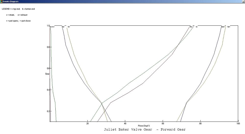 Sorry if it's not very clear but it's a screen capture and they are never brilliant. There are various diagrams to show the valve evnts but this is my favoured one as it clearly shows the equality (or otherwise!) of the port openings for both ends of the cylinder. The pairs of lines represent the position of the valve relative to the position of the piston for each end of the cylinder as the cut off alters. The lefthand nearly vertical pair (should be red and green) show when the valve opens to steam (admission) and the 2nd pair of red and green lines show when the valve closes (cut off). The blue and yellow pairs show when the valve opens and closes to exhaust. You can see that all the pairs are quite close together so the events are pretty balanced for both ends of the cylinder. You can also see that the admission points differ quite a bit for the two ends of the cylinder and this gets worse as the cut off increases. It's quite unusual for them to differ by so much and is no doubt due to something in the valve gear being not quite right. I doubt if it's enough to cause any real problems though. As mentioned, reverse gear is a bit strange:  Sorry if this has got a bit 'deep' The problem with all LBSC's Baker valve gears is that the type he uses is actually designed for inside admission valves, not outside admission slide valves. It's not a simple case of just swapping over the connection points on the top of the combination lever and moving the return crank. As it happens, he got away with it for Juliet but some other designs are way out because of this. There is a strange version of Baker gear that was specifically designed for outside admission slide valves but it was not very common. Bit off topic but I've seen critiscm of Martin Evans's design for the Baker valve gear on his Caribou but it's actually very good. That does use inside admission piston valves though. However, if you try substituting outside admission valves, it all goes pear shaped. I'm afraid Baker gear is not one I've got to grips with yet. Trying to 'tweak' it is still a case of altering the dimensions and seeing what happens without really knowing what I'm doing! John |
|
|
|
Post by Deleted on Nov 7, 2014 22:48:06 GMT
For interest, here's the event diagrams for the original and revised version of the Stephenson gear: Original:  Revised: 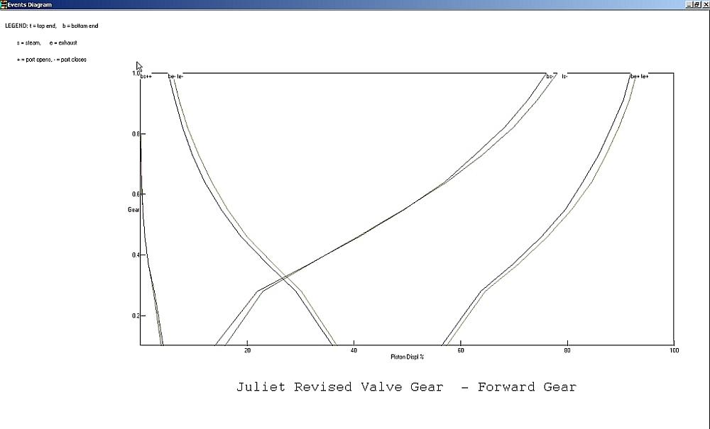 |
|
|
|
Post by GWR 101 on Nov 7, 2014 23:24:19 GMT
John many thanks for the information and your time in posting and your explanation, I will look over these in the cold light of day and hopefully gain a better understanding of what's actually happening. I struggled to understand how the gear actually worked but managed to grasp the fundamental principle only after I had constructed it. As I previously stated it seems to work ok but this is my first build and so I have very little knowledge of what is good or bad. Apologies again to DC for hijacking his thread. Regards and thanks Paul
|
|
|
|
Post by Deleted on Nov 8, 2014 0:09:25 GMT
Quote}--"Trying to 'tweak' it is still a case of altering the dimensions and seeing what happens without really knowing what I'm doing!".....that's just confirmed your Passport status as British then LoL !!
|
|
dc309
Seasoned Member
Posts: 146
|
Post by dc309 on Nov 8, 2014 21:36:50 GMT
I've had a couple of hours in my workshop tonight! Didn't have enough time to do my wheels, so I thought I'd utilise some material I had lying around and make some buffers. I think it must have been something along the lines of EN8 as it was really tough! They aren't exactly to drawing, but they look quite nice (although the finish doesn't look very good in the photos) I made 4 out of 1" round which I had a long length of, I just need to make springs and pins for them now It definitely isn't award winning stuff by a long shot, but it suits me    |
|
|
|
Post by Deleted on Nov 8, 2014 21:39:36 GMT
Hi DC, looking good!
What you got to remember is that it's your engine so if you are happy then that is all that matters!
Keep it up mate!
Cheers
Ben
|
|
|
|
Post by Deleted on Nov 8, 2014 21:40:51 GMT
looking good..... you'll find that a sanding sponge will take out most tooling marks, steel wool too. Cheers Pete |
|
dc309
Seasoned Member
Posts: 146
|
Post by dc309 on Nov 8, 2014 21:42:55 GMT
Thanks Ben! It's my first attempt so I'm actually quite chuffed! Pete, thanks for that bit of advice, I've got some steel wool but I never thought of using it. I'll rechuck them tomorrow and give it a go Dan |
|
|
|
Post by Roger on Nov 8, 2014 22:04:36 GMT
Well Done Dan, who cares about awards anyway. The point is that you started out with a piece of bar, and now you have some buffers. This is the joy of creating something out of almost nothing.
Just a word of caution.... I would never use any sort of abrasive on the lathe, not even with paper or a cloth to protect the ways. It produces a fine abrasive dust that settles on vital surfaces and ruins the lathe. You can always use an electric drill or some other way of spinning it round instead.
|
|
dc309
Seasoned Member
Posts: 146
|
Post by dc309 on Nov 8, 2014 22:13:13 GMT
Cheers Roger. I've got an Aldi pillar drill which is quite crap - I'll stick them in there to do it as it isn't very good anyway!
|
|
|
|
Post by Roger on Nov 8, 2014 22:25:06 GMT
Cheers Roger. I've got an Aldi pillar drill which is quite crap - I'll stick them in there to do it as it isn't very good anyway! Good idea....crap as it may be, it's still a whole lot better than no pillar drill! |
|
|
|
Post by Deleted on Nov 8, 2014 23:49:15 GMT
--------- and a sponsorship from Swafega ?? LoL !! "Nice set of buffers" ( Said the Bishop to the Actress ).....Yes, pillar drill for all that polishing stuff.. I de-coke all my motorcycle valves that way as well..
|
|
|
|
Post by Deleted on Nov 8, 2014 23:59:48 GMT
--------- and a sponsorship from Swafega ?? LoL !! "Nice set of buffers" ( Said the Bishop to the Actress ).....Yes, pillar drill for all that polishing stuff.. I de-coke all my motorcycle valves that way as well.. Did my car valves the same way a few weeks ago... |
|


