|
|
Post by Cro on Apr 2, 2020 20:14:36 GMT
Steve,
Fair point, having the bronze adapter will help to a degree it’s typically water space contact I’ve noticed causes the issues.
As Norm has said this regulator can be tricky, my experience driving a few is they like to close themselves and then sharp to open. I’m sure you’ll find a solution that works for you.
Adam
|
|
|
|
Post by springcrocus on Apr 4, 2020 7:33:17 GMT
A few more bits for the regulator assembly have been made, starting with the lump on the back. Both valves feed steam to this space which I shall call the regulator steam chest. From here, two pipes go to the wet header. After machining to size all round, the block was hollowed out in similar fashion to the regulator block. The fixing holes were drilled using co-ordinate positioning and the two holes for the pipes drilled ready for silver-soldering. The bottom cover was made next, again milling all round and drilled 4BA clear. No picture, it's just a flat plate. 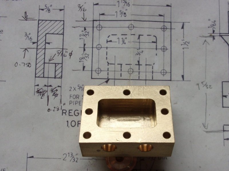 The regulator top plugs were made from 3/4" dia. brass stock, machining the front end in one go and parting off to length. Rather than the 9/16" x 26 thread that was specified, I have made mine M14 x 1 because I have a matching tap and die. 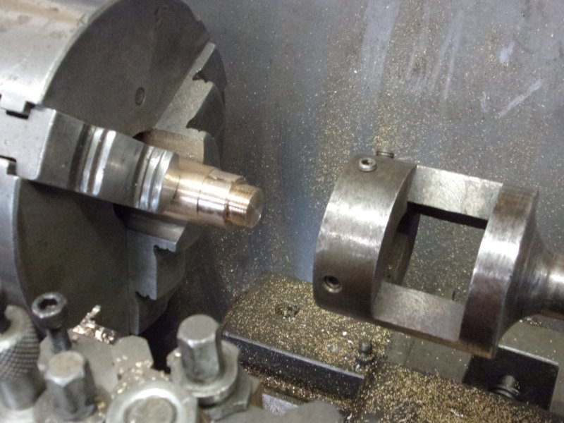 The regulator block was used as a milling fixture, screwing each plug in turn and tightening with mole grips. After finding centre and setting 0,0 on the DRO the square was milled to equal x-y co-ordinates, working full-depth and 25 thou steps. After the first pass, the plugs were tightened with a spanner before continuing to stop them unscrewing.  Steve |
|
|
|
Post by springcrocus on Apr 4, 2020 18:20:12 GMT
Plenty of workshop time at the present with this lockdown in place. Returning to the ashpan, the next thing done was to create the seating for it on the frames. I made a full-width support bar for the front from 1/2" x 3/16" flat mild steel, and milled the top at an angle of nine degrees to match the slope of the firebox. The rear support was made from two pieces of 5/16" square bolted together, only because I had no 5/8" x 5/16". These sit on the two support brackets which are already at the correct angle.  Each bar has a pair of 3/32" dia pins set in to locate the ashpan correctly and also to allow the pan to expand a little if needed.  The ashpan doors were made next as per drawing, along with the support blocks and the operating rod. These were then fitted to the two brackets on the side of the frames.  Whoever designed that was an idiot. The doors don't seal, are really difficult to adjust and ash will get in the mechanism all the time. Norm (old norton) sent me a picture of what he has made and I have blatantly copied his design. Thanks, Norm. The mechanism has been moved rearwards, the doors have an outer leaf to allow sealing and new arms have been made to suit.  Here is a picture of the new arrangement and, as can be seen, I've also silver-soldered the tunnels to the ashpan and filled that ridiculous slot for the cylinder cock operating lever. I will sort out something different for that, maybe a bowden cable. 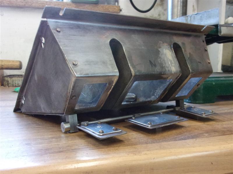 In this final view, the doors are closed and the operating lever can be seen to the side. Also on view are the end of the grate-lifting mechanism and a modification to the side of the ashpan.  After much deliberation, I have decided to go against all the advice and have made a one-piece grate. I really dislike the idea of trying to fiddle four sections of grate out through the firehole. Sorry, guys! However, I will say that the whole grate is removeable without lifting the boiler. In fact, it takes me about two minutes to get the grate out and four minutes to put the grate back in. But I will save that description for the next time. Steve |
|
|
|
Post by Jock McFarlane on Apr 4, 2020 18:35:30 GMT
I am interested in your ashpan modification as I am at the same stage in 7&1/4". I stuck with the original design for the doors but did manage to make them work. Have you considered that the original design allows the doors to be used as dampers or have you something else in mind for dampers ?
|
|
|
|
Post by springcrocus on Apr 4, 2020 21:37:55 GMT
I'm not sure I agree with you, Jock. With the original design, if the doors are tilted open the ash still falls all over the track whilst running. Not a popular move at most of our clubs, I would suggest. Dampers can be created in the tall front section if required but I don't think they will be neccessary at our scales. Air from the back should suffice but if I'm wrong they can be added later.
Regards, Steve
|
|
|
|
Post by Jim on Apr 5, 2020 5:26:32 GMT
I'm not sure if this helps but in the original works drawings the dampers can be seen as separate doors at the front of the ash pan and with the operating lever leading back to the cab.
The doors for dropping the ash can be seen as Steve has them in the base of the pan.
This view shows the the mechanism for opening the grates.
I decided being lazy by nature, to simplify the ash pan as drawn by Perrier to accommodate the Rosebud grate I fitted as an alternative to the bar grates shown in his drawings and as per the prototype.
Your ash pan and doors look great Steve, it's a pity such detailed work is hidden from sight.
Jim
|
|
oldnorton
Statesman
  5" gauge LMS enthusiast
Posts: 726
|
Post by oldnorton on Apr 5, 2020 8:59:38 GMT
Yes, lovely to see Steve, well done.
I agree that those ashpan doors have to stay tight shut during running. You might consider drilling 1/2" air holes at the top in the vertical faces front and back, and even either side of the frame tunnels. Perrier fails to show any, which I think is a big error - you need as many as possible.
Norm
|
|
|
|
Post by Jim on Apr 5, 2020 11:53:06 GMT
I'd agree with Norm. I did as he describes and added a row of holes to the front and rear of the ash to create a good air flow. As mentioned earlier I modified the ash pan to create a simple single unit with an opening at the bottom for the ash to drop through the opening in the frame of the pony truck. Sadly I didn't take a photo of the finished ash pan set up. 
Jim
|
|
|
|
Post by springcrocus on Apr 5, 2020 12:29:21 GMT
I will follow the advice and make some holes when the boiler next comes off, it's a bit heavy to keep lugging about. Maybe test my new hoist.  Hope you're keeping well, Regards, Steve |
|
|
|
Post by Jock McFarlane on Apr 5, 2020 12:35:31 GMT
I'm not sure I agree with you, Jock. With the original design, if the doors are tilted open the ash still falls all over the track whilst running. Not a popular move at most of our clubs, I would suggest. Dampers can be created in the tall front section if required but I don't think they will be neccessary at our scales. Air from the back should suffice but if I'm wrong they can be added later. Regards, Steve Hi Steve, I wasn't disagreeing with you but there have also been some other interesting ideas come up in subsequent posts which have helped me come to a conclusion. One of the problems of "suck it and see" is its pretty time consuming to go back and make modifications. So I have concluded that I will leave the doors as designed and they can either be used open for dampers (spilling ash as you suggest) or kept closed. I will also drill some air holes and then plug them so that some or all of them can be used when and if required. That way I hope I won't have to take the boiler off to make modifications. What do you think ? Regards Jock |
|
|
|
Post by springcrocus on Apr 5, 2020 14:28:50 GMT
I'm not sure I agree with you, Jock. With the original design, if the doors are tilted open the ash still falls all over the track whilst running. Not a popular move at most of our clubs, I would suggest. Dampers can be created in the tall front section if required but I don't think they will be neccessary at our scales. Air from the back should suffice but if I'm wrong they can be added later. Regards, Steve Hi Steve, So I have concluded that I will leave the doors as designed and they can either be used open for dampers (spilling ash as you suggest) or kept closed. I will also drill some air holes and then plug them so that some or all of them can be used when and if required. That way I hope I won't have to take the boiler off to make modifications. What do you think ? Regards Jock I can't answer that, Jock, I'm a machinist, not a loco driver. I'm happy to follow the advice of Norm and Jim if they both say there is likely to be too little air for combustion and will add air holes around the top of the pan. My thoughts about using the bottom doors as dampers is more about how your colleagues will feel if you keep setting fire to the sleepers everytime you go for a drive. 
Regards, Steve
|
|
|
|
Post by Jim on Apr 5, 2020 22:01:04 GMT
(snipped) .....My thoughts about using the bottom doors as dampers is more about how your colleagues will feel if you keep setting fire to the sleepers everytime you go for a drive.  Regards, Steve
As to the air flow through the ash pan, I'm not a loco driver either/ just a hobbyist having fun, but it just seemed a good idea to have a row of holes .25" from memory along the widest part of the front of the ash pan to get an even flow of air up through the fire especially given the design of the Rosebud style grate.
On the last steam up the mod certainly seemed to work well with the combination of fuel I was using ie charcoal, Bacchus Marsh Char and Welsh Coal. I had a nice even fire and constant steam pressure. This shows the 4 vent holes I added on the basis that 'they looked about right', not very scientific I know but what could possibly go wrong? If I was doing it again I would look at fitting a sliding 'shutter' strip that could be easily accessed from the side to reduce or close off the holes if the air flow proved to be too much.
Jim
|
|
|
|
Post by springcrocus on Apr 6, 2020 14:53:47 GMT
I was thinking something along the same lines, Jim, but you wrote it first.  The grate is made from 12mm x 3mm stainless steel flat bar, tied together with 5mm dia stainless steel rods and with 10mm dia spacers between the firebars. The width of the spacers are different front-to-back because of the firebox taper. The spacers were made first and, because there are fifty seven of them, a simple stop and part-off arrangement was set up to speed up production. I drilled about an inch deep and then parted off four in each batch, touch on, lock, part off, move along, touch on, lock, part off and so on.  Here is a closeup of the frontstop I made. The adjustable bar and locknut are threaded 1/4" x 40 tpi, which means 25 thou per revolution, same as a micrometer. After doing nineteen at 0.207" for the back row, the stop was adjusted and the next row done. The variation in each batch was no more than one thou.  The firebars were sawn to length, drilled to accept the 5mm rods and assembled with 5mm st.st nuts on the ends. The centre section drops, as per drawing, but I have moved the front tie bar for this further forward to better support the firebars.  I've had to use thin-headed screws on the drop-down section, though, because the nutted rods were fouling the sides of the ashpan tunnels. Steve |
|
don9f
Statesman
  Les Warnett 9F, Martin Evans “Jinty”, a part built “Austin 7” and now a part built Springbok B1.
Posts: 961 
|
Post by don9f on Apr 6, 2020 18:14:54 GMT
I’ve got to say it....that’s a grate job!
Don
|
|
|
|
Post by springcrocus on Apr 6, 2020 18:39:05 GMT
I’ve got to say it....that’s a grate job! Don I had a little bet with myself, wondering who would be first. Thought it might be Alan, seems I've lost my beer money. 
Regards, Steve
|
|
|
|
Post by springcrocus on Apr 7, 2020 17:16:19 GMT
As mentioned earlier, the grate comes out in it's entirety quite simply. Allowance has already been made for pipework and the injector in this area. The first photo shows the left-hand side of the ashpan. The lever is for the drop-grate feature and is in the grate-up position. The two bar-ends on view at the top of the ashpan are the cross-bars that the grate rests on. 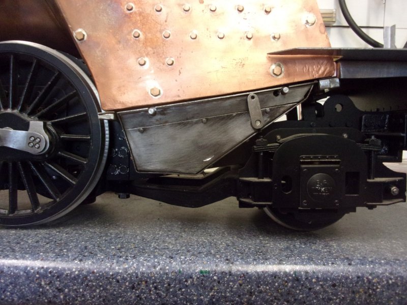 To remove the grate, I first drop the grate to it's lowest position and then remove the three screws circled. Sorry, the focus is a little out here.  The top panel of the ashpan then rolls forward and out. The grate support bars are now on view. The main body of the bars being a larger diameter than the ends ensures that the grate gets lifted up into the firebox rather than sit slightly below it.  The ashpan panel has a support strip silver-soldered to the back and is drilled and tapped in three places. The redundant hole near the rear support slot was in the wrong place, when the crossbar was here, the grate wouldn't drop fully. It's now an additional air hole. The longer spigots on the support bars stick out to the left and allow the grate to be shaken slightly up and down to help clear ash from the bars, effectively giving a rocking grate as well. 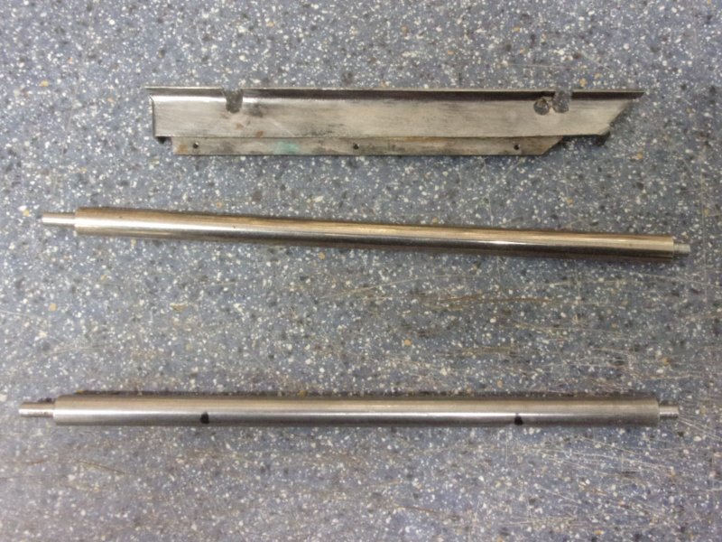 Before the two support bars are withdrawn, a stiff 12" rule is placed underneath the grate to allow withdrawal. This is a spare one from adjustable square and is thicker than a normal rule.  And, finally, a shot of the grate out of the loco. Because the grate rolls forward down the support bars, a couple of extra spacers (circled) were added to ensure the grate stays centrally within the box.  Replacement is just a reversal of these steps and takes less than five minutes. Not too onerous a procedure, I would suggest. Steve |
|
|
|
Post by Jim on Apr 8, 2020 0:05:57 GMT
That looks to be a good solution to a potential problem with extracting bar grates which is one of the reasons I opted for the Rosebud style grate apart from
the fact that its design also works well with our fuel.
Well done Steve it's a very nice neat idea.
Jim
|
|
|
|
Post by springcrocus on Apr 9, 2020 16:31:34 GMT
The drawing shows functional but not very prototypical top feed clacks so I have tried to compromise between the very simple drawing and the very pretty castings from Adam and others. I started by making the outlet section of the clacks that screw into the boiler bushes. A length of 3/4" dia brass was turned to 11/16" outside diameter and the front turned to 3/8" diameter by 3/8" long. This was threaded 3/8" x 32 tpi using a button die. A 3/16" diameter blind hole was drilled 1" deep, and multiple plunge cuts were made in the rear section with the parting tool to reduce the diameter to 3/8" by about 5/16" long.  The components were parted off 1.1/4" long and numbered. Each part was screwed into it's respective boiler bush and tightened down onto a fibre washer, then marked to show the front. Work now transferred to the mill. Using a previously-made hollow mandrel, the parts were screwed in and tightened with mole grips. Three sides of the top part were milled to leave the shape shown here and the back part was rounded off on the linisher to match the turned diameter.  Next, the mandrel was held in a vice at thirty degrees to the horizontal to allow machining of the top and front face of the outlet pipe.  The top was machined first, aimimg for a cleaned-up length of about 7/16" followed by the front until it just reached the first machining.  A view from a different angle 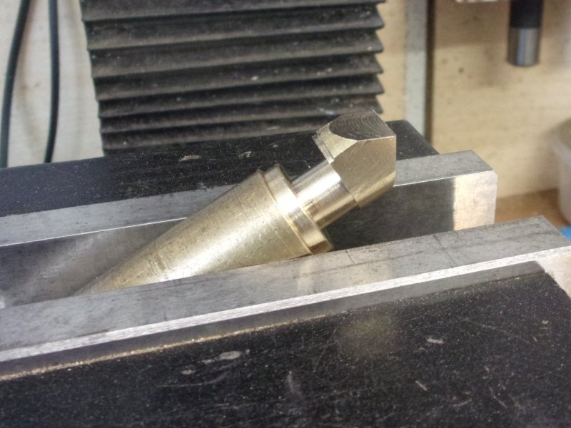 The mill was then centered on a point 3/16" in from the end and a 3/16" hole drilled to meet the hole up the centre of the part. This was followed by turning a 1/4" dia external spigot for 1/32" deep using a boring head with a home-made cutter in it. The boring head was then adjusted to machine a 3/8" dia down the neck until it met the main stem diameter.  The rest of the work on these parts were with files and sanding drums. After soldering, they can be cleaned up some more.  The next component was the pipe and flange for the inlet of the topfeed. This was machined from a piece of 5/8" square brass, turning the pipe section 1/4" diameter, drilling a 3/16" diameter hole and parting off to length. 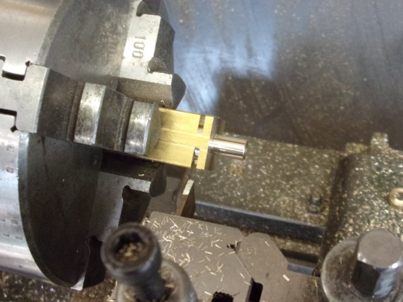 The four bolt holes in the flange were drilled on the mill on a 15/32" PCD using co-ordinate positioning. No centre drill, the PCB drills are rigid enough to start true as long as the chuck runs true.  The third part, the clack body, was made next, turning 1/2" diameter brass to 7/16" diameter, drilling the 9/32" hole with a spotface drill to form the ball seat and continuing with a 3/16" drill to 7/8" deep. The front was tapped 5/16" x 40 tpi and then the component was parted off 7/8" long. These were than taken to the mill and the seat for the outlet pipe machined. This is spotfaced with a 10mm slot drill and counterbored with a 1/4" slot drill by thirty thou deep, finishing by drilling through 3/16"" diameter. 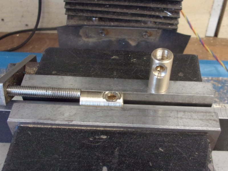 The bottom needs to have an access hole at 45 degrees for the inlet pipe and a simple locating jig was made from some MDF with a 3/16" dia pin set in. No need for a fancy fixture here.  Once set in the vice, a 1/4" slot drill was lined up with the corner by eye and plunged into the work until a full witness was obtained. I managed to mess up the first one, crushing it in the vice but, because I nearly always make a spare where parts need multiple operations, I took the opportunity to cut the first one in half and see where the slot drill met the 3/16" hole. I also screwed a plug into subsequent clacks for a bit of protection.  This showed that I could safely shorten the clack by another 1/8" which looks more prototypical. After facing off, they were returned to the mill and the angled hole completed. 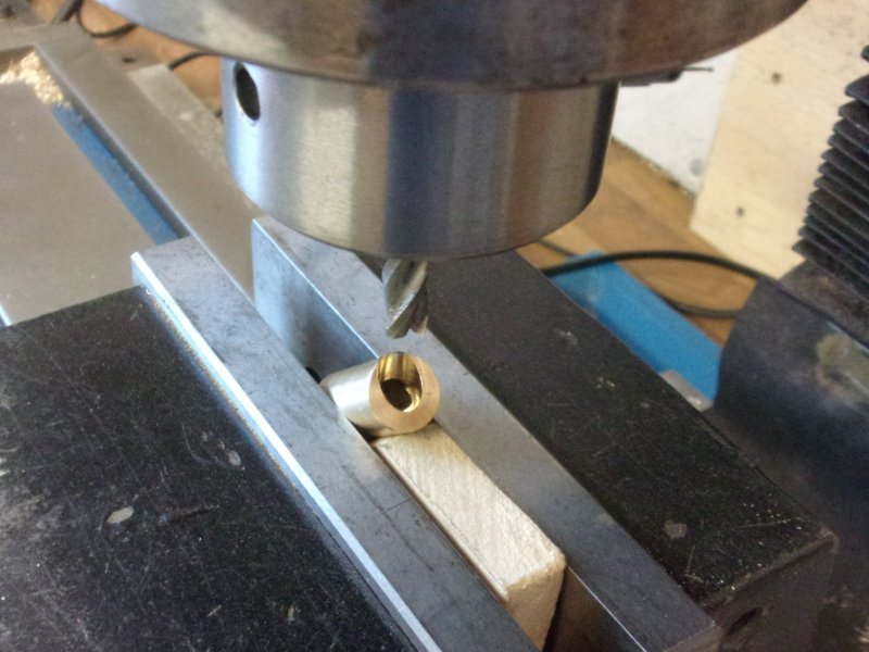 Then it was time to solder the three parts together. The pipe and flange were soldered to the body first using higher-temperature 40% silver. This was straightforward to hold and solder but the next bit needed a more complicated arrangement. There is a ring of 55% silver solder around the outlet pipe and, once the flux started to melt, all heat was directed to the inside of the clack body. This drew the solder down perfectly into the joint. 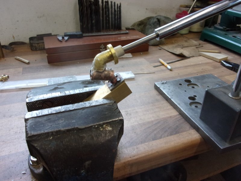 The fourth and final part was the screwed plug at the top of the clack. This was turned complete from 3/8" diameter brass.  The plugs were screwed into a hexagon mandrel and the flats machined on the mill.  The mandrel and component were returned to the lathe and the domed head formed on the top of the plug. 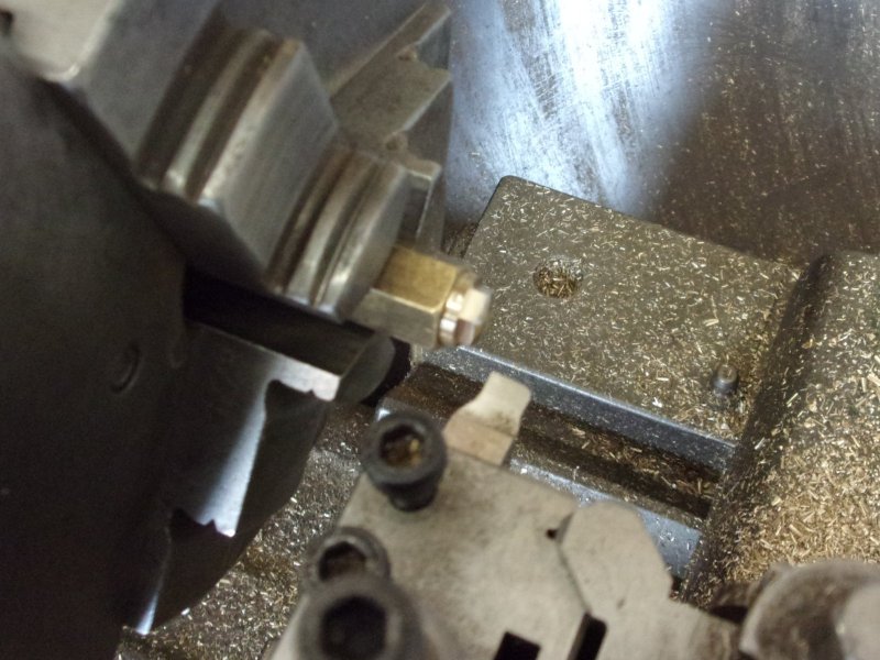 The rest was just filing and polishing. I'm quite pleased with the outcome, not as pretty as Adam's super-detailed castings but a bit better that what was drawn.  Lower clacks next, while I'm mostly set up for them. Steve |
|
|
|
Post by simplyloco on Apr 9, 2020 19:19:53 GMT
There's a lot of work there Steve. Excellent!
John
|
|
jma1009
Elder Statesman
  
Posts: 5,922
|
Post by jma1009 on Apr 9, 2020 22:08:52 GMT
Hi Steve,
Just be aware that ashpans and grates distort in service, especially in miniature!
Note also the lessons that were learnt from 'Duke of Gloucester'.
There is really no fire risk or smouldering sleepers from a loco going around a track emptying it's ashpan in the process. It is idiots who think they have to rake through the fire at every station on a stop, then agitate the ashpan to deposit hot coals who are the nuisance, and is why we fit guards over the sleepers at stations, though proper training of miniature loco drivers is really the way to go over all this! Though what can you say to someone who has been doing this for years and years and doesn't appreciate someone younger telling him he is doing something wrong!
(As I have stated more than once on here, the fire pricker was removed from my own locos when others were driving).
Nice job on the check valves BTW. Lovely job.
Cheers,
Julian
|
|