

Post by GWRdriver on Jun 13, 2007 21:04:55 GMT
Sorry for the delay in responding but for the last few days real life has brazenly intervened, and of course a useful description has turned out to be a bit more time-consuming than I first thought. This has created more of a buzz than I reckoned and a good deal of useful scutiny, which is a good thing I suppose. The first thing I needed to do was drag out the original boiler drawing for Maid of Kent (ca.1948) to see what was originally called for to help determine what were design deficiencies and what should be blamed on the builder. Although LBSC and I did not get along well, consideration must be given on certain points because the design is 60 years old and in that time we've made progress in model boiler practice. Whatever design deficiencies there are can be written off by saying "we don't do it thataway any more" but even so this one doesn't fall short of the mark by much. What I found is that this boiler deviated from the original drawings in a number of areas so most problems will be down to the builder in fabrication and soldering/joining.
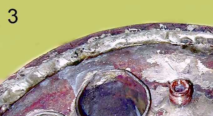
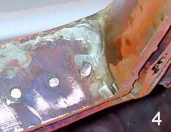
The first and to me most glaring problem is the use of a "spelter" (although called for on the original drawings) which I cannot identify but which I assume to be a brass alloy. Although it isn't apparent in the photos this spelter has distinct yellow caste to it. This is used throughout the boiler and I can detect no silver solder present in any area. In looking at all joints it become immediately apparent that there is no evidence of any capillary or wicking action at all and the spelter progressed no further into any joint than the outside surfaces of the joint, ie, the side from which the spelter was applied. (Photo 1 ) Every joint, flange, and seam is "dry" inside, that is devoid of solder or spelter on the inner surfaces. The most alarming condition is that the barrel lap joint strap shows no solder/spelter at all present between the barrel sheet and strap. There is however a rather copious surface accumulation, or fillets, of spelter piled up around or along every joint. (Photo 3 & 4)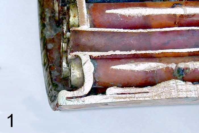
There are no bushings in the barrel for the top mounted safety valves and the original drawings do call for these. (Photo 2) The drawings also call for 1/4" longitudinal stays (4) to be threaded and nutted over at both ends and neither end is nutted. The dome ring bushing, which may certainly be insufficient by our standards, is as-designed. The builder decided to add a couple of additonal tapped holes to the backhead neither of which was bushed.
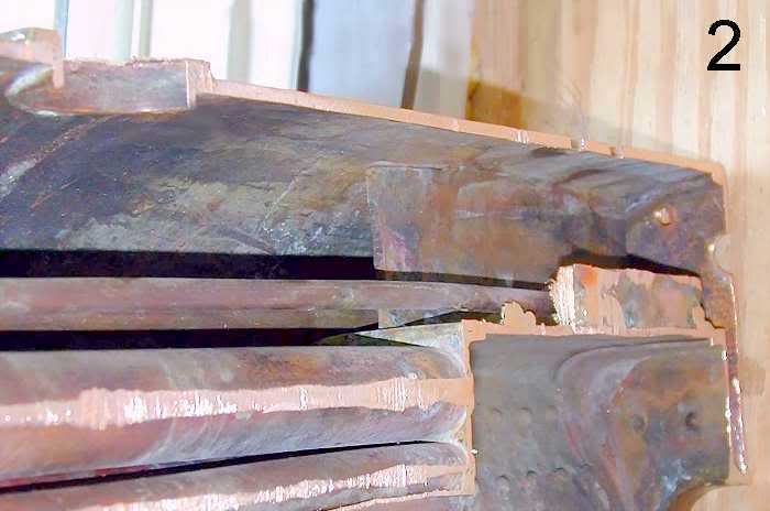
The drawings call for an outboard pair of 13ga double thickness girder crown stays, double flanged top and bottom, and riveted. What is present is single thickness, butt jointed and spelter tacked, with no flanges and no rivets, and as you may be able to see in the photo has no attachment at all for some distance from the end. (Photo 2) The central girder crown stay is doubled 13ga with flanged feet and is as-designed but again there is none to poor spelter penetration.
The firebox end on the other hand is thoroughly stayed with 1/8" snap head copper rivets at 11/16" O.C. which is as called for in the drawings. The only deviation from the drawings is that the rivet heads are inside the firebox, which is actually a preference I agree with. Stays occuring at the boiler center line were lost in sawing.
There is a noticeable difference in the flange radii of the backhead, firebox, and front flue sheet plates. The backhead and firebox head flanges have IMHO been formed with too little radius, while the front flue sheet does not have a sharp enough radius, so even if silver solder had been used the result would not have provided a full, sound joint. (Photo1)
Additional comments I have are that this boiler shell was roll formed from one continuous sheet of copper and it appears little attention was paid to ending up with an shell that was in decent geometrical alignment, that is with external surfaces that are straight, square, and/or parallel. Also, the LBSC design calls for 13ga firebox plates and wrapper and 10ga backhead and throat and my own inclination, since these surfaces are exposed to the most brutal conditions of any, is to make the firebox plates and wrapper at least as thick as any other part of the boiler.
Now I'll strep back and listen to whatever comments arise and maybe I'll learn something.
Cheers,
Harry
The first and to me most glaring problem is the use of a "spelter" (although called for on the original drawings) which I cannot identify but which I assume to be a brass alloy. Although it isn't apparent in the photos this spelter has distinct yellow caste to it. This is used throughout the boiler and I can detect no silver solder present in any area. In looking at all joints it become immediately apparent that there is no evidence of any capillary or wicking action at all and the spelter progressed no further into any joint than the outside surfaces of the joint, ie, the side from which the spelter was applied. (Photo 1 ) Every joint, flange, and seam is "dry" inside, that is devoid of solder or spelter on the inner surfaces. The most alarming condition is that the barrel lap joint strap shows no solder/spelter at all present between the barrel sheet and strap. There is however a rather copious surface accumulation, or fillets, of spelter piled up around or along every joint. (Photo 3 & 4)
There are no bushings in the barrel for the top mounted safety valves and the original drawings do call for these. (Photo 2) The drawings also call for 1/4" longitudinal stays (4) to be threaded and nutted over at both ends and neither end is nutted. The dome ring bushing, which may certainly be insufficient by our standards, is as-designed. The builder decided to add a couple of additonal tapped holes to the backhead neither of which was bushed.
The drawings call for an outboard pair of 13ga double thickness girder crown stays, double flanged top and bottom, and riveted. What is present is single thickness, butt jointed and spelter tacked, with no flanges and no rivets, and as you may be able to see in the photo has no attachment at all for some distance from the end. (Photo 2) The central girder crown stay is doubled 13ga with flanged feet and is as-designed but again there is none to poor spelter penetration.
The firebox end on the other hand is thoroughly stayed with 1/8" snap head copper rivets at 11/16" O.C. which is as called for in the drawings. The only deviation from the drawings is that the rivet heads are inside the firebox, which is actually a preference I agree with. Stays occuring at the boiler center line were lost in sawing.
There is a noticeable difference in the flange radii of the backhead, firebox, and front flue sheet plates. The backhead and firebox head flanges have IMHO been formed with too little radius, while the front flue sheet does not have a sharp enough radius, so even if silver solder had been used the result would not have provided a full, sound joint. (Photo1)
Additional comments I have are that this boiler shell was roll formed from one continuous sheet of copper and it appears little attention was paid to ending up with an shell that was in decent geometrical alignment, that is with external surfaces that are straight, square, and/or parallel. Also, the LBSC design calls for 13ga firebox plates and wrapper and 10ga backhead and throat and my own inclination, since these surfaces are exposed to the most brutal conditions of any, is to make the firebox plates and wrapper at least as thick as any other part of the boiler.
Now I'll strep back and listen to whatever comments arise and maybe I'll learn something.
Cheers,
Harry


