|
|
Post by joanlluch on Mar 3, 2018 11:23:11 GMT
I suppose this will be my final design for the boiler as it already meets all my strength analysis prerequisites. Mesh: 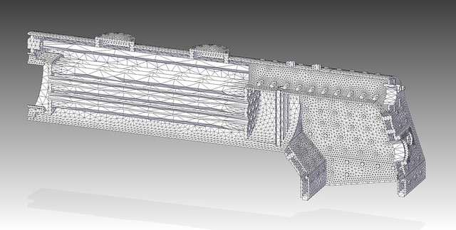 Boiler-Boiler-Simulacio-Mesh-E-7 Boiler-Boiler-Simulacio-Mesh-E-7 by joan lluch, on Flickr Video of stresses developing: As usual the video can be played in loop mode by right clicking on it and selecting "loop". This one is different from previous ones in that the boiler performs much better than any previous one. This allowed me to reduce the colour scale to a maximum of 1/4 of the material yield stress. Red colour in the video above would correspond to ONE QUARTER of the max stress the material can withstand with no permanent deformations, and it's NOT shown anywhere. Of course deformations shown in the video are overly exaggerated for illustration purposes. Another difference is that for simulation I only constrained the edge of the barrel at the smokebox side as opposed to the entire front plate. I found this gives better simulation information at the smokebox side of the boiler, which is now shown to deform as we would expect. The following is the Factor of Safety results with a range of 4 to 20. 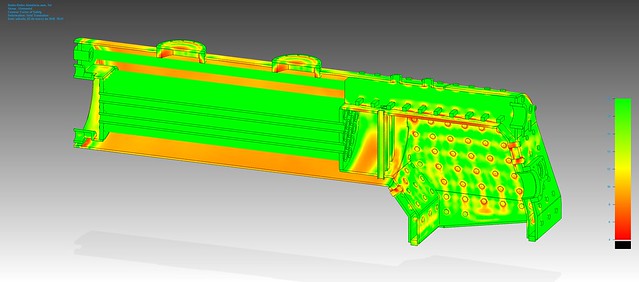 Boiler-Boiler-Simulacio-E-7 Boiler-Boiler-Simulacio-E-7 by joan lluch, on Flickr Anything below 4 would show black on the picture, which is no longer happening with this design. Getting there has required more work that it may seem because any changes require individual editing of boiler parts, rearrangement of the boiler assembly for accounting for changes in parts, and recomposing of parts connectors for simulation. Compared with my previous attempts, this boiler has the following differences: - I returned to the original inclinations of the backhead and throatplate. I also allowed a vertical throatplate section for most of the part around the barrel. I think the boiler looks better overall with these visual changes. - Stays have bigger diameter, 8 mm instead of 6 mm. They are more spaced apart in safe areas such as the sides and back of the boiler, but closer together on the throat plate. - The crown bars have more, smaller anchor points. Their position has been optimised to minimise stress. - The water tubes in the firebox have been moved towards the right (in the picture) in order to support better the beginning of the firebox extension. - I replaced the elongated dome by two round ones. The one placed at the longitudinal centre of the boiler is the steam collector dome. The one towards the smokebox is meant to give access to the 'main steam valve'. This can be regarded as the regulator, but it's not THE actual regulator. This valve placed inside the boiler will be there for safety purposes. The actual regulator will be placed in the smokebox and will take superheated steam. So this is how the locomotive currently looks. 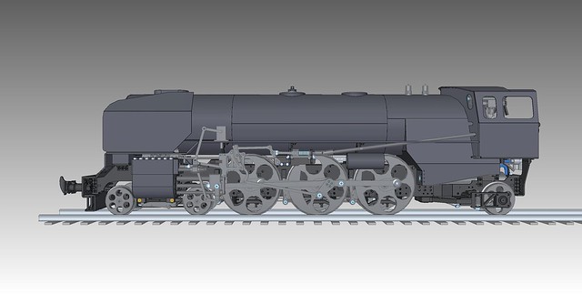 LocomotiveAssembly LocomotiveAssembly by joan lluch, on Flickr To my taste the loco looks better and more "European" with this boiler design. I'm satisfied so far with the results. (Sorry for the wheels, I'm not currently happy with how they look, but they had a reason to be like that) Joan |
|
|
|
Post by joanlluch on Mar 29, 2018 19:45:17 GMT
I made some progress on the steam pump. As a matter of reference, this is the intended design. 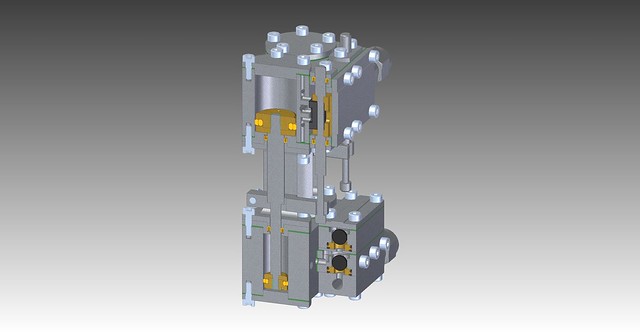 BombaVapor-Corte BombaVapor-Corte by joan lluch, on Flickr I got the cylinder blocks for steam and water machined by the CNC service. They only made the external shape and the main bores (although I didn't order the later) This is what they delivered: 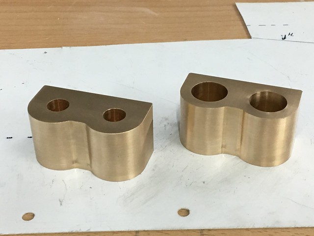 Bomba Bomba by joan lluch, on Flickr I made all the internal machining and drilling of the steam and water passages. The following few pictures were taken at several intermediate steps: 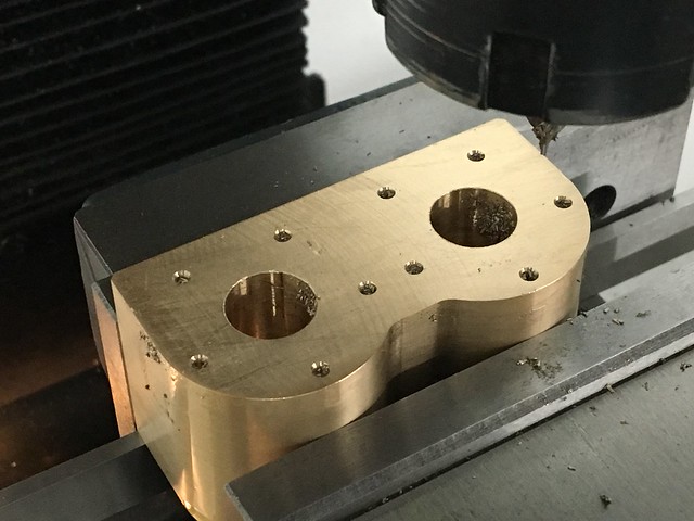 Bomba Bomba by joan lluch, on Flickr 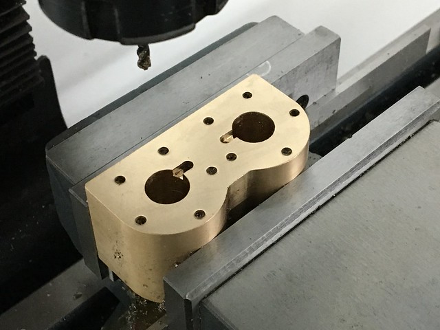 Bomba Bomba by joan lluch, on Flickr 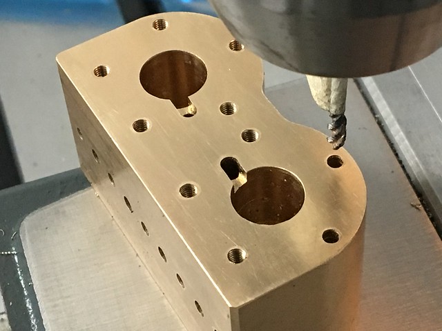 Bomba Bomba by joan lluch, on Flickr 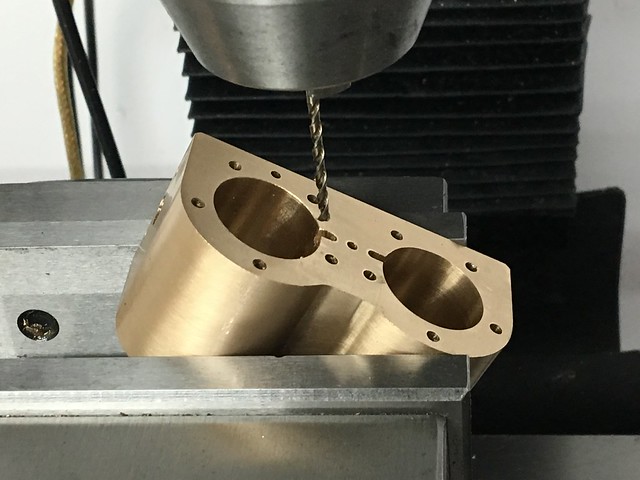 Bomba Bomba by joan lluch, on Flickr 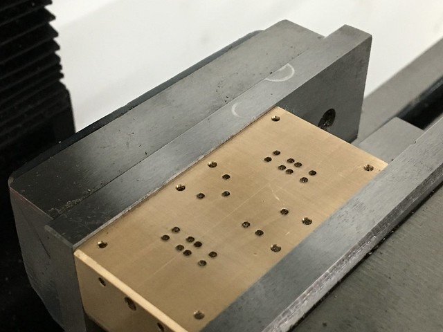 Bomba Bomba by joan lluch, on Flickr This is a minor mistake I made, but it's unimportant because that was only a couple of centre drill spots in the wrong place, which don't have any influence and they won't show in the assembly: 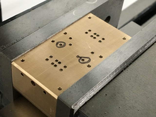 Bomba Bomba by joan lluch, on Flickr The cylinder block for steam already finished looks like this: 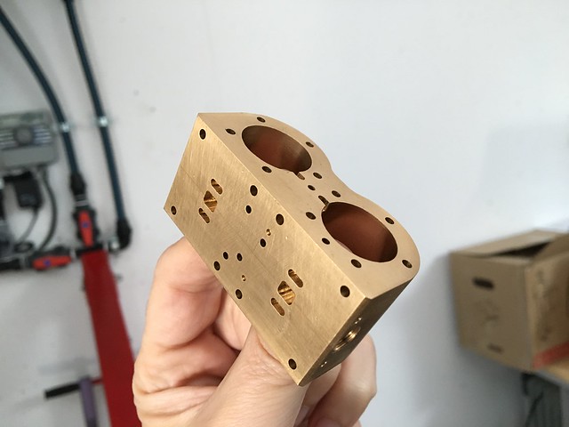 Bomba Vapor Bomba Vapor by joan lluch, on Flickr |
|
|
|
Post by joanlluch on Mar 29, 2018 23:24:09 GMT
I also collected all the remaining lathe parts made by the CNC service: 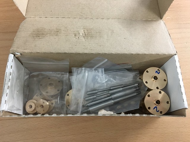 Bomba Vapor Bomba Vapor by joan lluch, on Flickr This is a photo of all the machined parts for the steam pump. The ones on the left paper sheet required only a mill tool so they were made by me from solid bronze or brass. The ones on the paper sheet on the right required a lathe (which I do not currently have) so I ordered them to the CNC service.  Bomba Vapor Bomba Vapor by joan lluch, on Flickr I also made special tools that I will use to screw the steam and water pistons to the common spindle. I used 2 mm commercial hardened steel dowels and stainless steel rod to make them. These are some photos of the making: 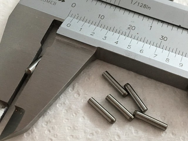 Bomba Vapor Bomba Vapor by joan lluch, on Flickr 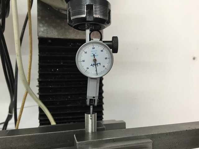 Bomba Vapor Bomba Vapor by joan lluch, on Flickr 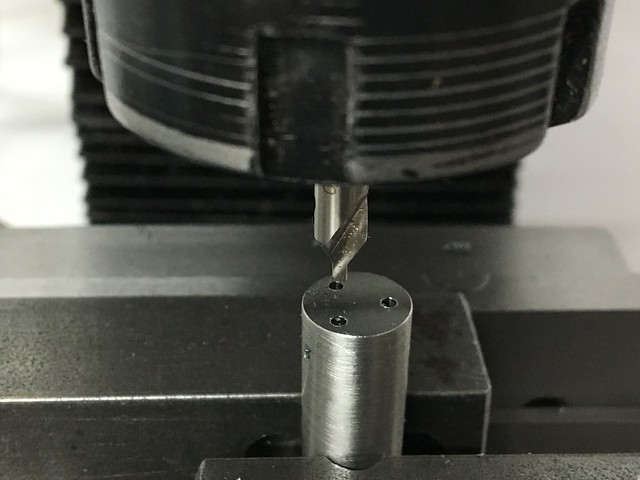 Bomba Vapor Bomba Vapor by joan lluch, on Flickr 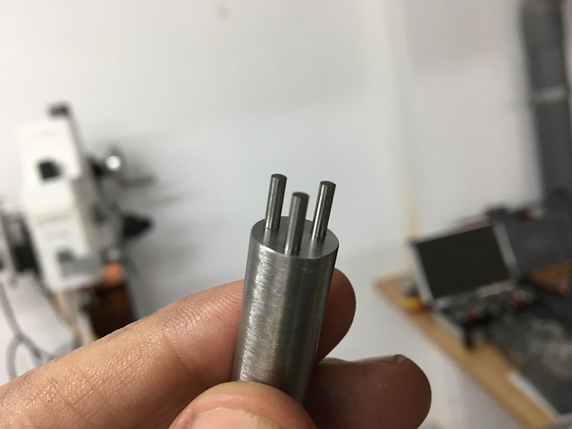 Bomba Vapor Bomba Vapor by joan lluch, on Flickr 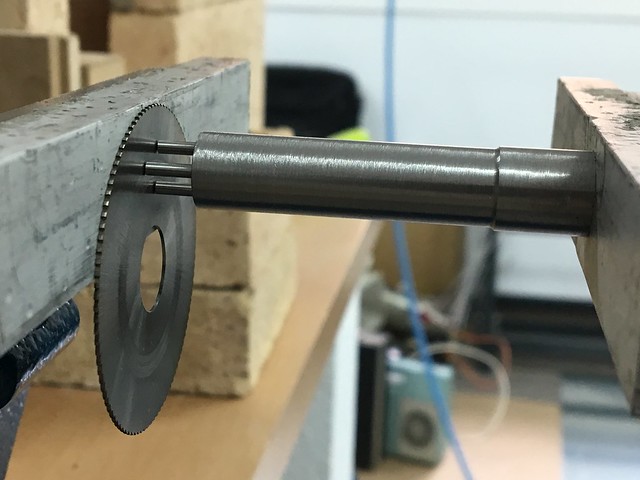 Bomba Vapor Bomba Vapor by joan lluch, on Flickr 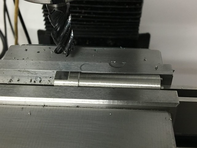 Bomba Vapor Bomba Vapor by joan lluch, on Flickr 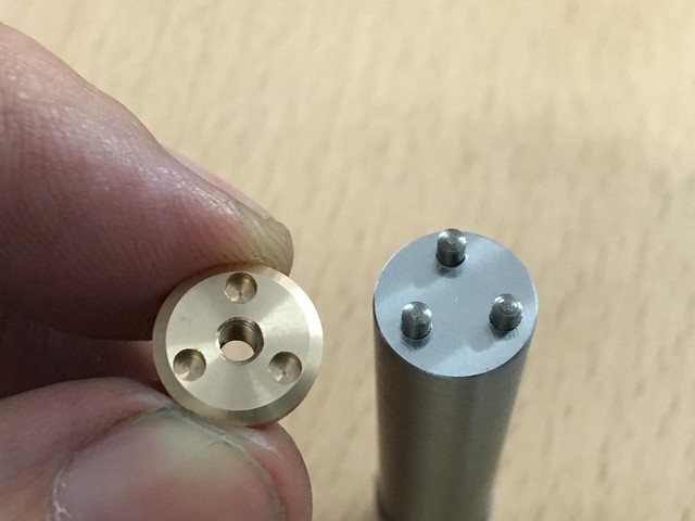 Bomba Vapor Bomba Vapor by joan lluch, on Flickr I will also need an additional tool to insert the rod seals in place. These have been ordered to the CNC service. The following photo shows them all, including the ones that I made: 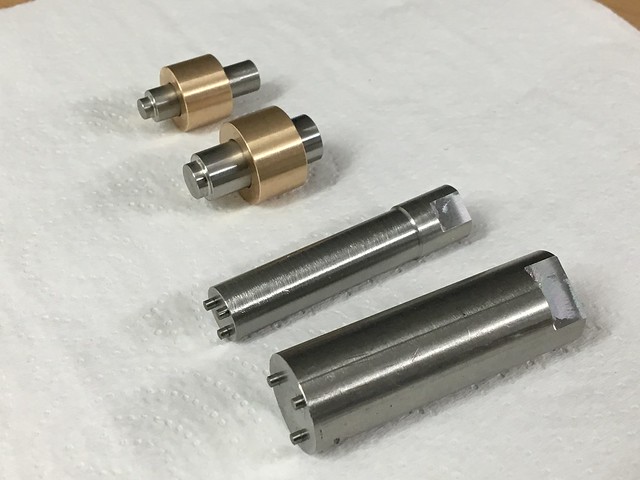 Bomba Vapor Bomba Vapor by joan lluch, on Flickr And this is the photo of all the commercial items that will be in the pump, including piston and rod seals, ceramic balls for the water valves, and 1 mm thickness FKM (viton) o-rings for the replaceable ball seats: 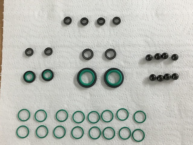 Bomba Vapor Bomba Vapor by joan lluch, on Flickr These are the ball seats showing the o-ring sealing radially on the upper body: 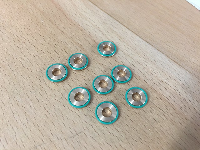 Bomba Vapor Bomba Vapor by joan lluch, on Flickr And here they are shown in place with the bottom o-ring sealing against the lower body. 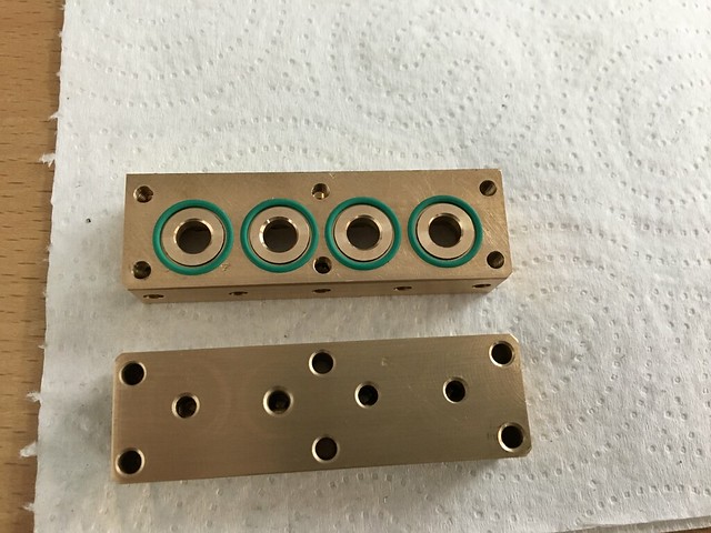 Bomba Vapor Bomba Vapor by joan lluch, on Flickr Next, I show several pictures of the water valves at several assembly stages: 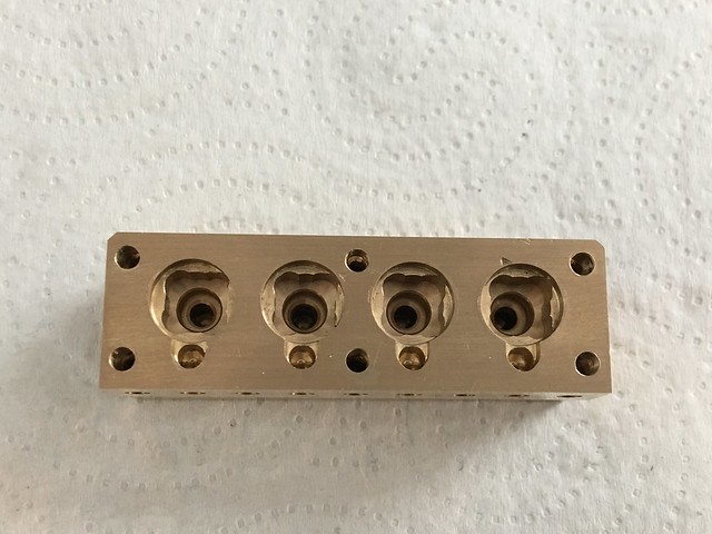 Bomba Vapor Bomba Vapor by joan lluch, on Flickr 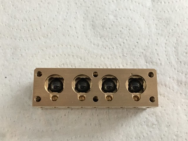 Bomba Vapor Bomba Vapor by joan lluch, on Flickr 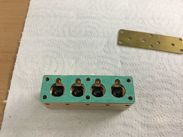 Bomba Vapor Bomba Vapor by joan lluch, on Flickr 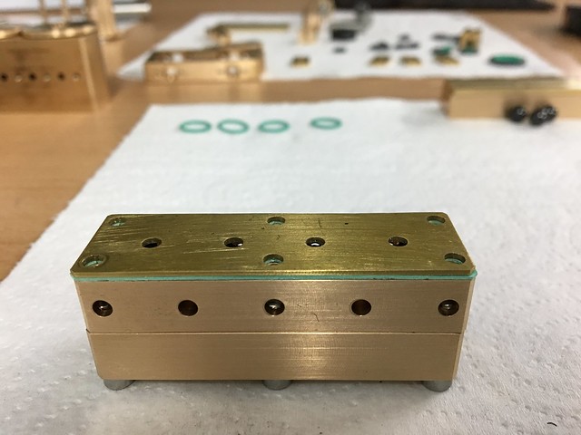 Bomba Vapor Bomba Vapor by joan lluch, on Flickr 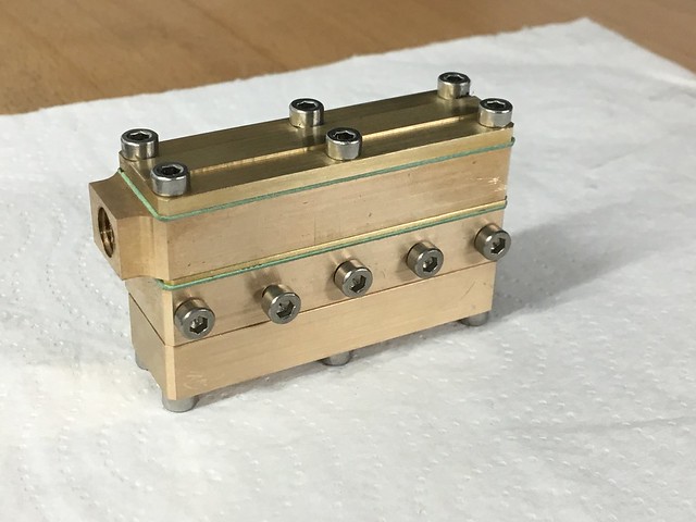 Bomba vapor Bomba vapor by joan lluch, on Flickr This design for the water valves is a bit more complicated than the usual one, but it has the advantage that the internals are fully accessible, the balls are fully guided when lifted, and the ball seats are replaceable in case they get some wear or a different material or geometry wants to be tested. |
|
|
|
Post by steamer5 on Mar 30, 2018 0:39:41 GMT
Hi Joan,
Nice looking parts & nice work on your bits!
Like the idea on the pump with the ball cavity's & replaceable seats, Murphys law will be that you will never have a problem having done that.
Cheers Kerrin
|
|
|
|
Post by gingerneer on Mar 30, 2018 18:26:01 GMT
Really nice crisp work.
|
|
|
|
Post by joanlluch on Apr 1, 2018 21:12:34 GMT
All the holes drilled in the pump to create the steam passages need to be sealed. I will do that by screwing short 2.5 mm stainless set screws into them, but some material hasn't arrived yet, so I'm stuck for now with the pump While waiting for the screws to arrive, I decided to replace the steam valve bobbins, as per the input that I got on this thread modeleng.proboards.com/thread/12384/valve-gear-lead. The problem with the former bobbins was that they were designed with the metal edges in mind for the valve events rather than the seal edges. Since the valve events were defined anyway by the seal edges, these bobbins caused an exaggerated lead that was beyond any logic and needed correction. Lead was as much as 15 degrees with the former bobbins. The new bobbin design has all the features that were suggested to me on the referred thread: 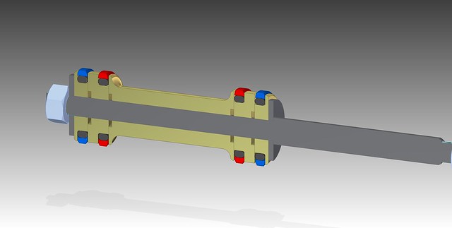 PistonValveAssembly PistonValveAssembly by joan lluch, on Flickr These are the parts for the new bobbins: 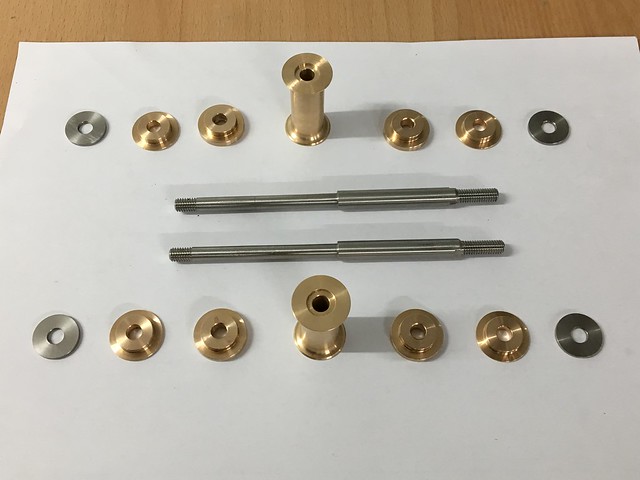 Nova corredera Nova corredera by joan lluch, on Flickr Some details of the extraction of the old ones:  Nova corredera Nova corredera by joan lluch, on Flickr 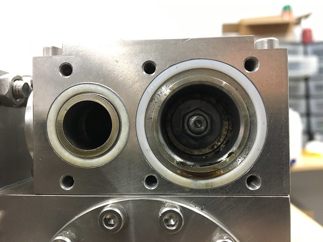 Nova corredera Nova corredera by joan lluch, on Flickr 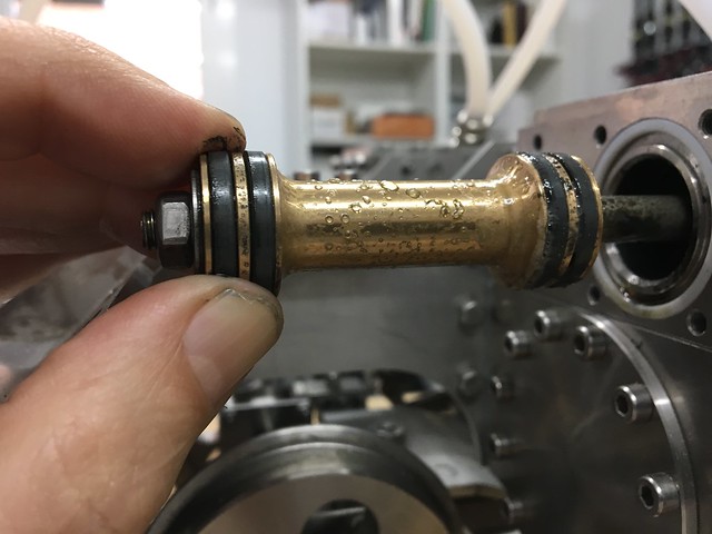 Nova corredera Nova corredera by joan lluch, on Flickr These are the parts that were reused from the old bobbins and incorporated again to the new ones, including the valve seals and the ptfe rings that go between the split parts: 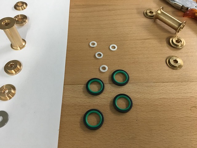 Nova corredera Nova corredera by joan lluch, on Flickr Following is a comparison of the old (top) with the new (bottom). On the new bobbin the seal edges are in the place of the old bobbin metal edges. The new one has the metal edges chamfered as suggested. The overall assembly is stronger because all the split parts are packed between two 1.5 mm thick stainless steel washers: 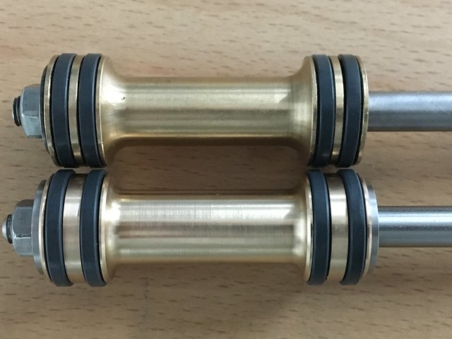 Nova corredera Nova corredera by joan lluch, on Flickr This is a photo of the two new bobbins fully assembled and ready to be mounted in the locomotive: 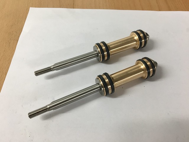 Nova corredera Nova corredera by joan lluch, on Flickr Finally, this is a VIDEO of the locomotive running on air with the new valves fully adjusted. (VIDEO should appear by clicking on the picture below) 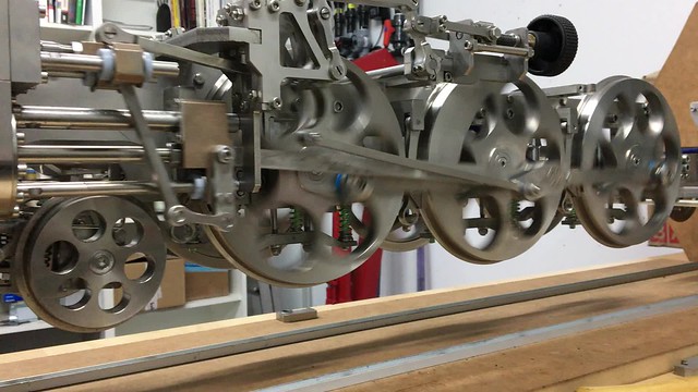 Nova corredera Nova corredera by joan lluch, on Flickr As expected, the locomotive no longer has such an exaggerated lead. While adjusting the valves I found that in fact the locomotive has virtually ZERO lead. Now, the loco can be run steadily with the reverser very near the mid position, which was not possible before. Overall, the locomotive runs smoothly on air in all circumstances. I hesitated very long to perform this change, and I even considered to do it after the loco was fully finished or already tested on steam, but I'm happy to have done it now and I'm very pleased with the result. Joan |
|
|
|
Post by Jim on Apr 1, 2018 21:54:15 GMT
Wonderful Joan to see your loco running so smoothly on air. It's a great sense of satisfaction isn't it to see it all work just as you planned and hoped for.
Superb workmanship too.
Jim.
|
|
|
|
Post by joanlluch on Apr 1, 2018 22:13:56 GMT
Wonderful Joan to see your loco running so smoothly on air. It's a great sense of satisfaction isn't it to see it all work just as you planned and hoped for. Superb workmanship too. Jim. Thanks Jim. I’m just learning from the ones who were at it before. Your build has taught me a lot of useful tips that I will eventually use as the loco nears completion. |
|
|
|
Post by Oily Rag on Apr 2, 2018 21:36:22 GMT
That is nice, genuine model engineering. Well done.
|
|
|
|
Post by steamer5 on Apr 3, 2018 11:23:33 GMT
Hi Joan,
What a great outcome! Cant wait to see how she will run on steam cause she sure runs sweet on air!.
Cheers Kerrin
|
|
|
|
Post by chris vine on Apr 3, 2018 11:51:56 GMT
Hi Joan,
She is running very smoothly on air so she will run even more smoothly on steam!!
Chris.
|
|
|
|
Post by ilvaporista on Apr 3, 2018 14:14:39 GMT
That video is hypnotic, I could almost fall asleep to that. Lovely and smooth motion. I am not sure that I would want to paint that, it's a joy to look at as it is.
|
|
|
|
Post by joanlluch on Apr 3, 2018 14:52:36 GMT
That video is hypnotic, I could almost fall asleep to that. Lovely and smooth motion. I am not sure that I would want to paint that, it's a joy to look at as it is. I got hypnotised also on a couple of occasions while watching the real thing moving (not just the video). Well, at least until the air compressor kicks in at the most unexpected time and suddenly wakes you up with its loud noise. About painting, my original idea was leaving several kinds of surface finish on different parts, for example creating shinny surfaces in some of them and several degrees of mate finish on some others. This is theoretically possible given it's all stainless steel. However, after some time I suppose I got my feet on the ground and realised that this would be impossible or very difficult for me to achieve considering my limited set of skills and lack of patience for such kind of things. Also laser cut parts tend to have rough faces which makes fixing them very time time consuming. So I finally decided to do what everybody else eventually does, which is painting the loco. Yes, since it's all stainless steel, even painting can be a bit challenging, but I hope still easier than my original goal and clearly less pretentious. I still like stainless steel very much as a material, and I'm happy to have chosen it for some parts such as the connection rods and other moving parts that I will leave unpainted, but I suppose that if I had to start over with a new locomotive I would make at least some parts in more conventional materials such as brass or bronze. Joan |
|
stevep
Elder Statesman

Posts: 1,070
|
Post by stevep on Apr 3, 2018 16:34:41 GMT
Very impressive, and extremely smooth Joan. The exhaust beats sound great on air - and they are always better on steam under load, so it should sound fabulous.
|
|
|
|
Post by joanlluch on Apr 7, 2018 12:52:52 GMT
The missing items for the steam pump finally arrived, a M2.5 tap and M2.5x3 set screws, so I spent some time yesterday and today assembling the remaining bits. 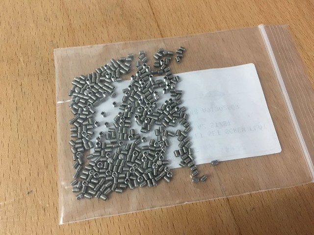 Bomba vapor Bomba vapor by joan lluch, on Flickr These screws are used to externally seal the holes that I made to create the steam passages, so these holes need to be threaded to M2.5 before that: 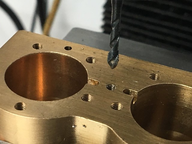 Bomba vapor Bomba vapor by joan lluch, on Flickr I had to improvise a 1.3 mm allen key made from a 1.5 mm key, as I was unable to quickly find the appropriate one: 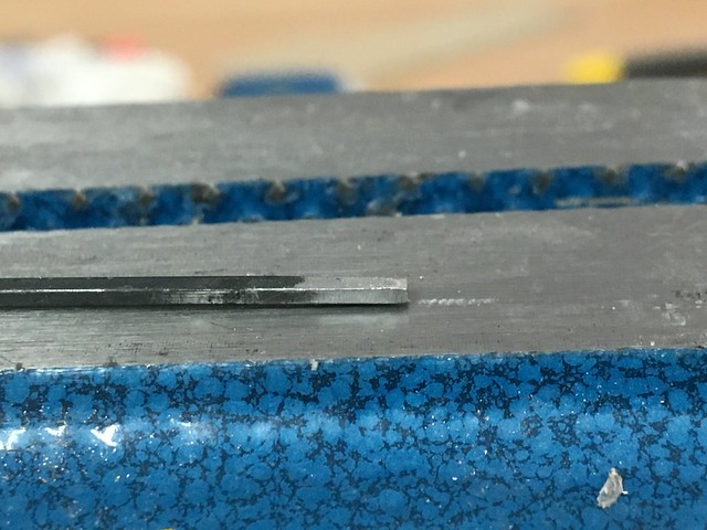 Bomba vapor Bomba vapor by joan lluch, on Flickr I used a high temperature sealant product to make sure there's no leaks around the sealing screws: 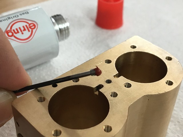 Bomba vapor Bomba vapor by joan lluch, on Flickr I took a lot of photos of the pump assembly steps as a matter of documentation. The first picture shows one of the spindle seals inserted in the tool, ready to be pushed into one of the inner pump covers, and the seals already in place and on the pump body: 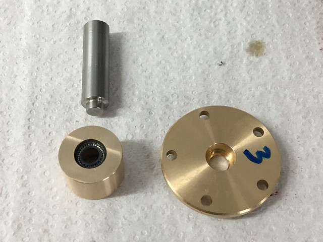 Bomba vapor Bomba vapor by joan lluch, on Flickr 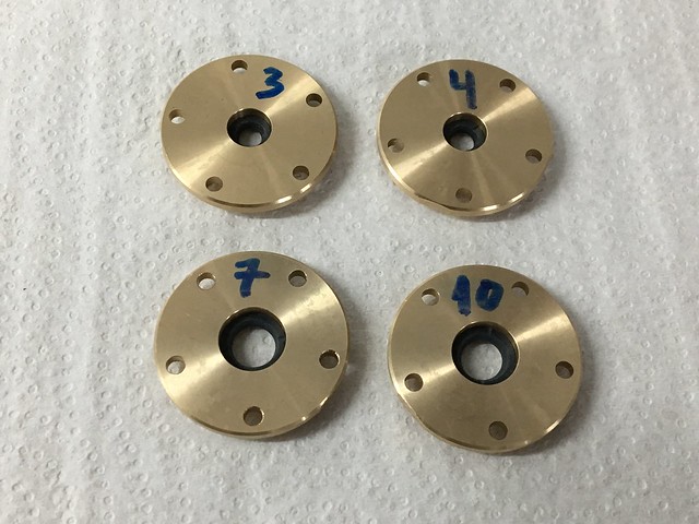 Bomba vapor Bomba vapor by joan lluch, on Flickr 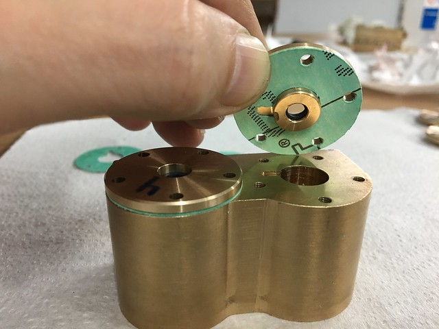 Bomba vapor Bomba vapor by joan lluch, on Flickr The spacers being screwed in place: 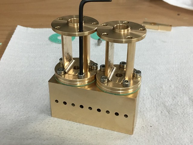 Bomba vapor Bomba vapor by joan lluch, on Flickr The piston rods with the actuator arms: 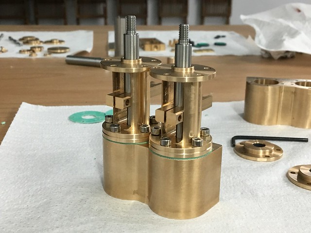 Bomba vapor Bomba vapor by joan lluch, on Flickr Steam cylinders body with some detail photos of this stage: 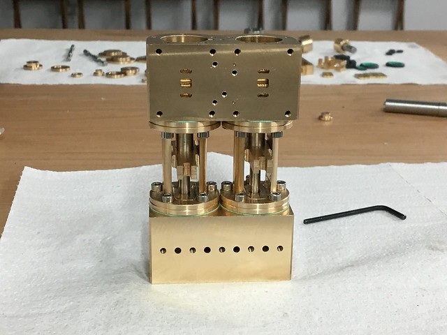 Bomba vapor Bomba vapor by joan lluch, on Flickr 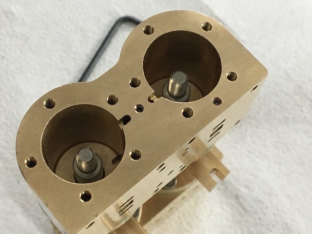 Bomba vapor Bomba vapor by joan lluch, on Flickr Piston seals and pistons assembly, for both water and steam sides: 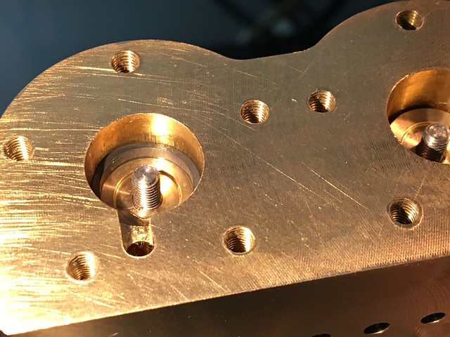 Bomba vapor Bomba vapor by joan lluch, on Flickr  Bomba vapor Bomba vapor by joan lluch, on Flickr 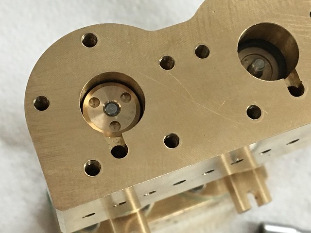 Bomba vapor Bomba vapor by joan lluch, on Flickr 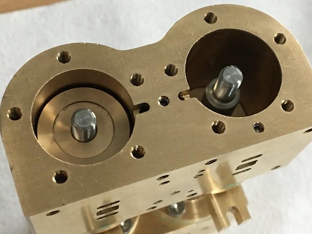 Bomba vapor Bomba vapor by joan lluch, on Flickr 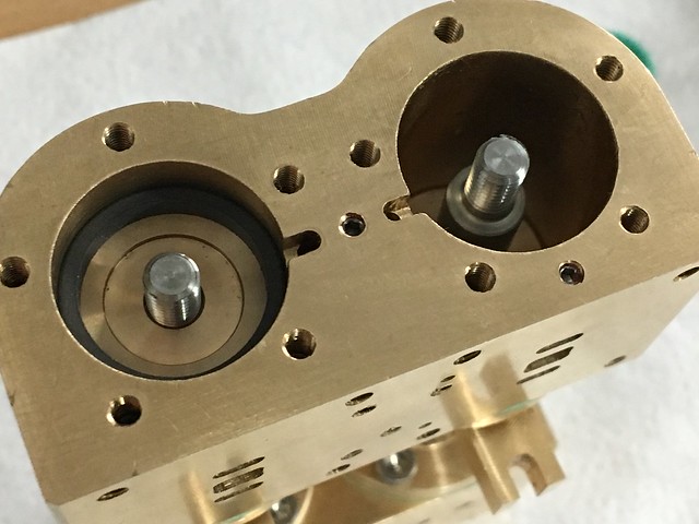 Bomba vapor Bomba vapor by joan lluch, on Flickr  Bomba vapor Bomba vapor by joan lluch, on Flickr Securing both sides of the piston rod with the tools I made on purpose: 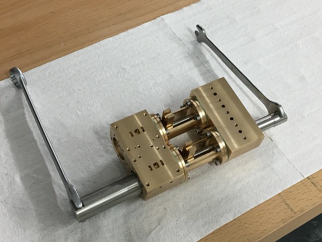 Bomba vapor Bomba vapor by joan lluch, on Flickr The pump with the water and steam bodies fully assembled: 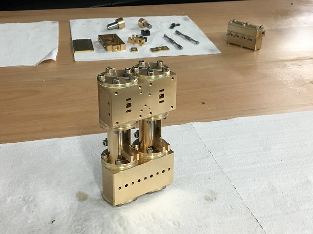 Bomba vapor Bomba vapor by joan lluch, on Flickr Next, is the assembly of the steam valve set, starting by inserting the valve spindle seals: 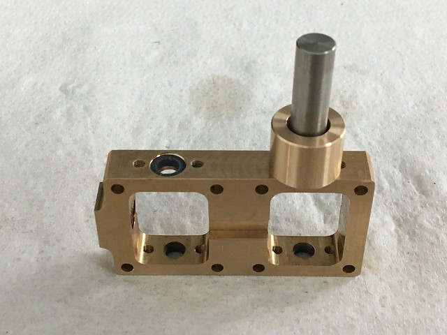 Bomba vapor Bomba vapor by joan lluch, on Flickr The valve spindle seal covers are fixed by means of through hole threads, so the screws must be sealed with sealing sealant in this case: 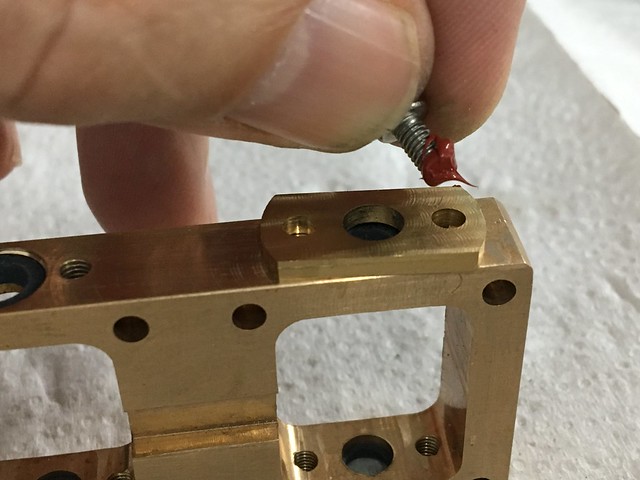 Bomba vapor Bomba vapor by joan lluch, on Flickr Valve spindles in place: 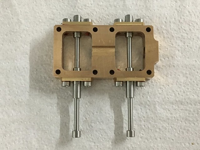 Bomba vapor Bomba vapor by joan lluch, on Flickr General pre-assembly view of the valve set, and partial assembly of the same, ready to be screwed onto the steam cylinder block: 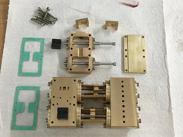 Bomba vapor Bomba vapor by joan lluch, on Flickr 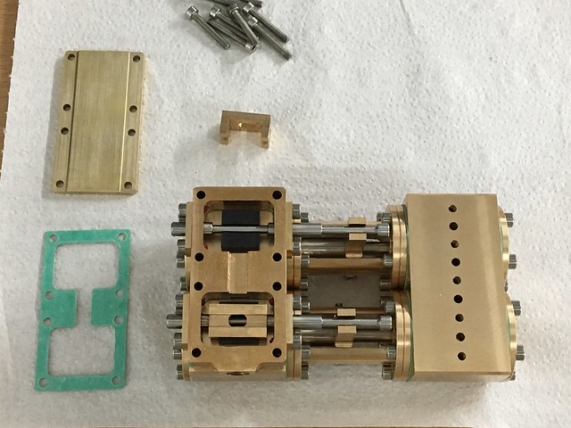 Bomba vapor Bomba vapor by joan lluch, on Flickr Two views of the pump fully assembled, except the water valves that appear far on the photo, ready for the air test: 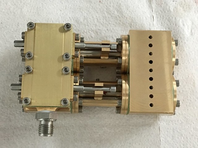 Bomba vapor Bomba vapor by joan lluch, on Flickr 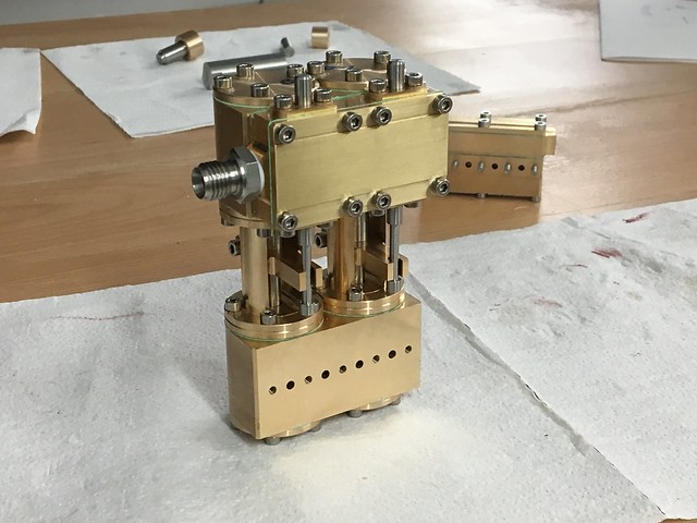 Bomba vapor Bomba vapor by joan lluch, on Flickr Finally, a VIDEO of the first test on air. (The VIDEO should appear after clicking on the picture below) 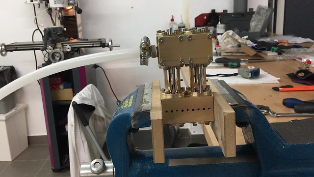 Bomba vapor Bomba vapor by joan lluch, on Flickr I'm happy (even impressed) to see that the pump runs so well, however there's some audible air leak, so that's what I need to figure out next. I just hope it's not any of the rod seals, that would be difficult to fix. Joan |
|
peteh
Statesman
 Still making mistakes!
Posts: 760
|
Post by peteh on Apr 7, 2018 14:17:04 GMT
Very nice Joan, and very satisfying!
|
|
|
|
Post by joanlluch on Apr 7, 2018 16:51:00 GMT
I solved the leaking issue described above. The leak was in ALL 4 seals for the actuator rods at the the steam chest. The cause is more easy to visualise than explain. See this: 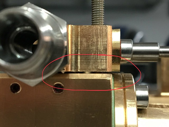 Bomba vapor Bomba vapor by joan lluch, on Flickr The photo above shows the gap between the steam chest and the cylinder block with the green (Klinger) gasket removed. The gasket has a nominal thickness of 0.5 mm and it is meant to fill that gap. The thickness of the gasket was taken into account during the design stages to make the steam valve slider just touching the ports surface. So in fact the photo above shows the 'natural' position of the steam chest as the valves rest on top of the ports. The gap shown is (and it should be) exactly 0.5 mm, in order to be filled by the gasket when assembled. The gasket thickness as new is in fact a bit oversized, almost 0.65 mm, so that adds some practical gap between the valves and the ports. The problem was that as the gasket got compressed, the valves were pushed slightly against the ports (instead of slightly floating over them) thus forcing the valve rods to some eccentricity with respect to their seals, as opposed to become guided by their own seals as per the intended design, and thus leaking. The solution has been reducing slightly the height of the valves. I removed 0.2 mm of them. 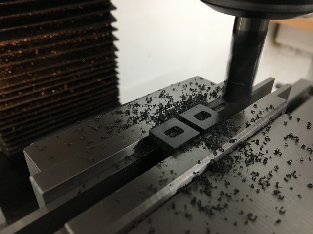 Bomba vapor Bomba vapor by joan lluch, on Flickr So after assembling again the pump it doesn't leak anymore: (The following VIDEO should appear after clicking on the picture below)  Bomba vapor Bomba vapor by joan lluch, on Flickr As shown in the video, I checked for external leaks by closing the exhaust with my finger. When closed, the pump obviously stops, but at that time no audible air leaks are present. Still, the pump seems to waste some air through the exhaust. This is suposedly due to some inefficiency of the sliding valve on air. I assume (and hope) that the valve will work more efficiently on steam. Joan. |
|
|
|
Post by jon38r80 on Apr 7, 2018 19:23:27 GMT
I hope you are really pleased with yourself, I would be, that's a beutiful piece of work
|
|
|
|
Post by Jim on Apr 7, 2018 19:25:51 GMT
A beautiful piece of skilled craftsmanship Joan and lovely to admire, well done.
Jim
|
|
|
|
Post by chris vine on Apr 7, 2018 19:50:05 GMT
Hi Joan,
Just wonderful and highly satisfying for you to have designed, built and now tested your pump.
It seems to run very smoothly!
Chris.
|
|


