|
|
Post by Jim on Mar 22, 2019 19:13:47 GMT
Reg you have years and years ahead of you.
I turn 80 in a few months time and don't plan on going anywhere until I finish the Bolton Beam Engine and I haven't even got the castings yet though I do hope to get them next weekend. Then there's the Britannia to take over to the club for a steam test, crikey I'm slacking there.
Go for the Peppercorn Reg and don't worry about the years they are just numbers. 
Jim
|
|
|
|
Post by RGR 60130 on Mar 30, 2019 13:58:30 GMT
As I continue to look at drawings, convert them to CAD and play around with scaled drawings, a few things are becoming cast in stone and will form the basis of the rules for the build. • The boiler and castings will be as per the Michael Breeze designed Peppercorn A1 ‘Sea Eagle’, if for no other reason than I already have the boiler and most of the castings. • The original main frames were made in two parts with an overlapping section. In this model the frames will be made in one piece and be over-scale in thickness (3mm). • The frame profile will, in the main be exactly as per full size, scaled by a factor of 0.0885. The horn cut-outs will be re-sized to suit the castings. • The distance between the main frames will be 4-1/8” which is slightly smaller than scale. • The main stretchers will be slightly narrower to suit the 4-1/8” dimension. • On the full size engine, the driving and coupled wheels are very close together. To accommodate the over-scale flanges of the model, the flange diameter will be to scale and the tread diameter reduced accordingly. Other things will no doubt become evident as I progress. In the mean time I’ve got another works drawing copied into CAD. Reg 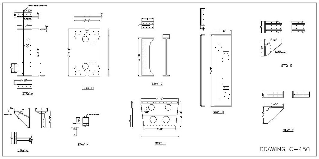 Peppercorn A2 Works Drawing O-480 Peppercorn A2 Works Drawing O-480 by reg.rossiter, on Flickr |
|
|
|
Post by silverfox on Mar 30, 2019 23:31:38 GMT
Reg
I must be seeing thing but i am sure you have sent me a mesage the other day...only i cant see it anymore.
But if you did. At thr moment everything is ok.. If you didn't, consider this to be the ramblinga of a demented idoit!!
Ron
|
|
|
|
Post by RGR 60130 on Apr 2, 2019 12:54:08 GMT
Getting the works drawings into CAD continues, this time concentrating on the drag beam arrangement. The drag beam is made up of the main drag box, two brackets that fit between the inner and outer frames, two buffer plates and a rubbing plate. The model will no doubt get lifted by the drag beam so strength here is highly desirable. I will probably use one piece of steel for the drag beam but profile it to represent the individual components. There is also potential to make the main drag box and brackets in one assembly, notching out the inner frames where required. Reg  Peppercorn A2 Works Drawing A-151-N Peppercorn A2 Works Drawing A-151-N by reg.rossiter, on Flickr 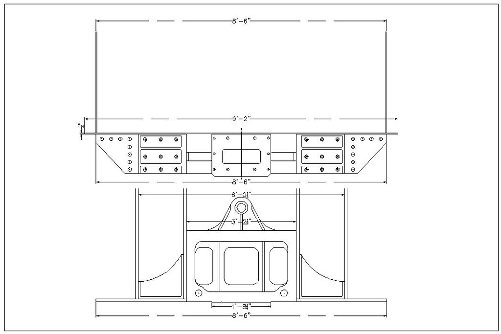 Peppercorn A2 Drag Beam Assembly Peppercorn A2 Drag Beam Assembly by reg.rossiter, on Flickr |
|
|
|
Post by Deleted on Apr 2, 2019 15:39:52 GMT
I have a drag box that looks very similar to that..  Pete |
|
|
|
Post by RGR 60130 on Mar 3, 2021 10:23:23 GMT
The design work continues and I am getting to the stage where the General Arrangement drawing is starting to look the part. I started machining the cylinder castings for my A1 many years ago before I bought the castings for the A2 which were also part machined. Given that I needed to get the cylinders done for my A1, I decided to do both sets together. Everyone has their own methods and I won’t be so brazen as to suggest this method is the best. Most importantly, it works for me on this pair of locos. If a pessimist is an experienced optimist then that is me for sure. I tend to do a mental risk assessment of everything that can go wrong with a job and implement risk control measures accordingly. Some of this attitude probably comes from engineering at sea where there’s no next day delivery if you make a cock-up. With this in mind, whenever I need to position a hole relative to other faces, typically in cylinders or axle boxes for example, I like to square up the castings leaving plenty of meat on them, bore the hole and then bring the castings down to final size relative to the hole. I do appreciate that this isn’t always an option and that many people will have had years of success using an edge finder and maths. Each to their own. The outer and bolting faces of the outside cylinders are parallel to each other which makes life much easier. With the aid of files, engineers blue and a surface plate I firstly got the outer faces reasonably flat – not perfect but flat enough not to rock. I also ran a file across the bottom of the cylinders where the drain cocks locate. These would be my reference surfaces. I got the castings squared up one face at a time on the lathe and mill before giving them a last tidy up on the surface grinder - very much a ‘nice to have’ but I enjoy being out in the shed with the door open watching and listening to the birds while cranking the table back and forth, most therapeutic. For the inside cylinder the reference faces were the left hand side and the drain cock flats. While machining the inside cylinder it was immediately obvious that the bottom of the cylinder was chilled. Yes, you can use carbide tools etc. to machine such but its better sorted properly before you have to start drilling and tapping for bolts and drain cocks. I bundled all the castings in a box and took them to a place in Dundee while passing through on a trip south (I lived in Morayshire at the time). I explained the issue and they heat treated them all for the princely sum of £10 ready for collection on my return North. I don’t have a lot of photos available though the following will show a few of the operations. The important thing is to make sure the vertical slide is clocked dead true to the axis of the lathe. You only need to bring the vertical slide down until the two clamping bars kiss the wood packings. The tightening is done on the clamping screws.  Photo1228 Photo1228 by reg.rossiter, on Flickr Printing a CAD drawing on overhead projector film allows you to see exactly how the casting matches the required item. 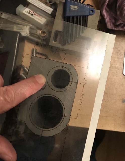 Transparent cylinder drawing Transparent cylinder drawing by reg.rossiter, on Flickr Packing up the castings so the middle is around the spindle centre line height means you can use a shorter fly cutter which means less spring and more rigidity.  Photo1229 Photo1229 by reg.rossiter, on Flickr  Photo1233 Photo1233 by reg.rossiter, on Flickr  Photo1236 Photo1236 by reg.rossiter, on Flickr  Photo1219 Photo1219 by reg.rossiter, on Flickr I’ll get some more pictures to show the boring operations in the next instalment. Reg |
|
timb
Statesman
 
Posts: 512 
|
Post by timb on Mar 3, 2021 10:55:41 GMT
'Printing a CAD drawing on overhead projector film allows you to see exactly how the casting matches the required item'
Inspired, why didn't I think of that!!??
Well done Reg, excellent work!
Tim
|
|
|
|
Post by RGR 60130 on Mar 4, 2021 9:25:37 GMT
This photo shows what I was hoping to achieve and what I used to do it. There’s a selection of shims for packing the castings up to the required height, 2 plug gauges and 3 between centres boring bars.  Cylinder boring ops 02 Cylinder boring ops 02 by reg.rossiter, on Flickr The first of the plug gauges is a coarse one machined to final size -0.010”, -0.020” & -0.030”. The second one is final size, -0.002” & -0.004” I also used a commercial plug gauge of 1.249” diameter for the piston valve bores (not shown). 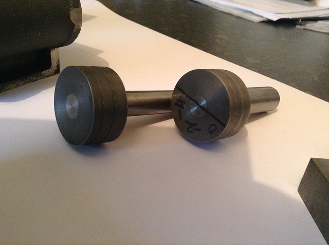 Plug gauges 01 Plug gauges 01 by reg.rossiter, on Flickr The two between centres boring bars I made utilise ground up ¼” diameter HSS shanks from broken centre drills or milling cutters. Adjustment is made using a ¼” x 40tpi screw. One turn of the screw therefore moves the tool out 25 thou. The 5 black marks in Sharpie pen are therefore 5 thou intervals. Locking of the bit after adjustment is by a 4BA grub screw. I believe G.H.Thomas did a posh version of this if you have the time and inclination.  Home made boring bars 01 Home made boring bars 01 by reg.rossiter, on Flickr I also had a commercial boring bar of the right size for the main piston bores with fully calibrated adjustment that is very easy to use.  Commercial boring bar 02 Commercial boring bar 02 by reg.rossiter, on Flickr This photo shows an outside cylinder casting ready for boring with the two datum faces I used nicely dressed with the surface grinder. A milled finish would have been fine too.  Outside cylinders Outside cylinders by reg.rossiter, on Flickr This is the set-up I used for boring the main piston bores in the outside cylinders. With the cross slide firmly locked this gave a very repeatable set-up. Having set the boring bar I then machined each of the castings one after the other before setting another cut and doing them all again to the same stage. Honing followed the boring op using some hones I once bought in the States and honing oil from Polly.  Boring outside cylinder 2 Boring outside cylinder 2 by reg.rossiter, on Flickr Having moved the cross slide across and locked it, then inserting a 13/16” shim, the piston valve bores were all done. Again, I did all 4 at the same setting of the boring bar before putting another cut on.  Boring outside cylinder 3 Boring outside cylinder 3 by reg.rossiter, on Flickr The inside cylinders were done in exactly the same way. The shims I used were obviously different but the cross slide positions were the same.  Boring middle cylinder 1 Boring middle cylinder 1 by reg.rossiter, on Flickr Finally, I now have the bores completed on two sets of cylinders. The next step is to take them down to final size.  Cylinders 01 Cylinders 01 by reg.rossiter, on Flickr Hopefully someone will be able to take something from this and find it helpful in some way. Reg |
|
|
|
Post by Deleted on Mar 4, 2021 10:25:21 GMT
excellent work Reg and it's great to see progress on your loco's, keep going...  Pete |
|
|
|
Post by coniston on Mar 4, 2021 22:13:56 GMT
Great Reg, well done, it's always good to see different methods and set ups to the same tasks.
Chris D
|
|
|
|
Post by gwr1509 on Mar 6, 2021 7:21:38 GMT
Thank you Reg for this documentation and the pictures. This is a valuable help to me. Please report further.
Helmut
|
|
|
|
Post by RGR 60130 on Sept 17, 2021 15:45:30 GMT
Things have moved on over the last six months since I last updated this thread. Decisions and progress have both been made! After a bit of thought I decided to dismantle the P2 rolling chassis and salvage the wheels, axle boxes, horns etc. for this A2 project (that should sound familiar to LNER followers). This put a whole new twist on the erection of the frames. There’s no opportunity to fit the horns in the frames and machine them as a pair. The workmanship on the P2 horns looked good but couldn’t be guaranteed. I therefore decided to design a stand-alone chassis centre section that I could use to test everything for fit and squareness and then use for other trial fits later on. An order was placed with Ed and Holly at Model Engineers Laser and a couple of weeks later the dummy centre section arrived.  DSC00025 DSC00025 by reg.rossiter, on Flickr The whole thing is made of 3mm steel plate and only needed 4 x 8BA bolts tapped into each side of the longitudinal stretcher to keep it all together. The leg lengths are such that the wheels will be at the correct ride height when it’s all stood on a flat surface. The sticky up bits at the top are at running plate height. With the horns and split axle boxes in place a set of ¾” diameter dummy axles was made up. The leading and trailing axles had 3/8” diameter spigots on the ends while the middle axle had ½” spigots. These match the crank pin sizes. A pair of 3mm laser cut dummy connecting rods were found to fit on the dummy axles no problem. Result! My attention then turned to the wheel sets. The P2 had the crank axle on a pair of wheels with large balance weights whereas the A2 needs the crank axle on the leading pair of wheels with small balance weights. Two of the axles therefore needed removing from their respective wheels and this is where there was a bit of a twist. It transpired that while the axle bearing surfaces that run in the axle boxes were 0.750”, the bores of the wheels were 0.754”. After a bit of deliberation I decided to go for 20mm axles so re-bored all the axle boxes accordingly. Another set of (20mm) dummy axles was made and the dummy rods still fit – relief! The wheels are currently in the process of getting steel tyres fitted so I’ll come back to them another day when I get some photos. Reg |
|
|
|
Post by silverfox on Sept 17, 2021 17:05:56 GMT
Reg
A +1 for the overhead printing. The B17 will have mostly works drawings stretchers and they will be adjusted to suit the holes as specified on Malcolms Drawings I just wish that my dragbox was a neat as the A2!!
Ron
|
|
|
|
Post by RGR 60130 on Sept 18, 2021 9:45:35 GMT
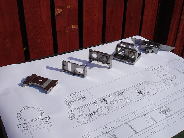 DSC00028 DSC00028 by reg.rossiter, on Flickr An hour or two of drawing most mornings over the last few months has resulted in an ever increasing collection of stretchers. I’ve used a 4 step process, namely; • Draw the stretchers out full size • Shrink them down by a factor of 0.0885 • Adjust the widths to suit the frame spacing • Produce a set of laser cut profiles using metric plate The quality of cutting from Model Engineers Laser has been excellent such that all the stretchers will stay together as seen in the following photos. Brake stretcher  DSC00037 DSC00037 by reg.rossiter, on Flickr  DSC00035 DSC00035 by reg.rossiter, on Flickr The brake cylinder and bell crank fit underneath this. Inside expansion link stretcher 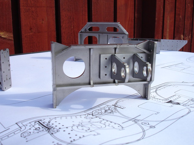 DSC00034 DSC00034 by reg.rossiter, on Flickr Inside motion stretcher 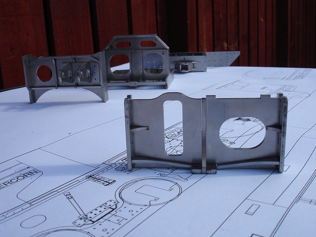 DSC00032 DSC00032 by reg.rossiter, on Flickr There’s a strip to bend and fit across the top of this one. I was happy to learn that this stretcher is at right angles to the slide bar rather than being vertical with the slide bar bolting pad machined at an angle. That will make assembly much easier. Bogie bolster stretcher 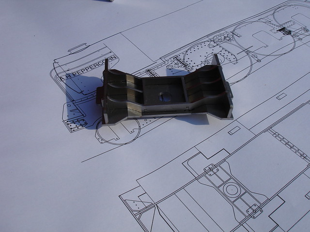 DSC00029 DSC00029 by reg.rossiter, on Flickr Not the best photo but you’ll get the idea. Drag box and drag beam  DSC00039 DSC00039 by reg.rossiter, on Flickr  DSC00040 DSC00040 by reg.rossiter, on Flickr On this I opted to make a 1 piece drag beam rather than have it in 3 sections. Buffer beams and drag beams often get used to lift locos and I wanted the strength to be there just in case of a derailment when all the fancy handling ideas go out the window and it comes down to a few men and a lot of grunt to get it back on the track. The safety link slots will also provide convenient attachment points for secondary coupling arrangements to be used where clubs require it. The rubbing plate is shown temporarily held in place by a couple of bolts until I get it flush riveted on as per original. Project Manager  DSC00018 DSC00018 by reg.rossiter, on Flickr Costing me a fortune in sausages but worth every penny! Reg |
|
|
|
Post by Deleted on Sept 18, 2021 10:25:00 GMT
excellent work Reg...dog looks cute too...  |
|
kipford
Statesman
  Building a Don Young 5" Gauge Aspinall Class 27
Posts: 575 
|
Post by kipford on Sept 18, 2021 16:34:46 GMT
Reg
Great work. I did a similar exercise on my Aspinall and ended up with about 150 parts laser cut, which saved an awful lot of work.
Dave
|
|
|
|
Post by davewoo on Sept 19, 2021 5:56:38 GMT
Reg
Thank you for posting this, it's an excellent thread with superb workmanship, I have never thought of using the vertical slide as a register and clamping aid, or of using a 40 tpi thread to advance the cutter in a boring bar. Both genius ideas that will come in very handy as I'm about to bore my cylinders for Aspinall, just waiting on the rings from Mr Smith at Clupet.
The great thing about these build logs is there is always something new to learn from others build methods,something learned every time I log on, please keep up the good work.
I've seen Pearl Diver in action, this will be a beautiful and powerful engine, can't wait for the next installment!
Dave
|
|
|
|
Post by RGR 60130 on Oct 2, 2021 9:29:25 GMT
Because the driving wheels on the A2 are so closely spaced, I have opted to make the flange sizes to scale and use slightly reduced tread diameters. Doing this meant that I needed to reduce the diameter of the wheels I stole from the P2 rolling chassis. Given that I was going to have to re-machine the treads I thought I might as well fit steel tyres at the same time. I obtained 6 heavy gauge pipe slices from Blackgates Engineering. These were 7"OD x 5.5"ID x 3/4" thick – plenty big enough. After 19 hours of machining I ended up with a matching set of 6, 3 of which are shown here. 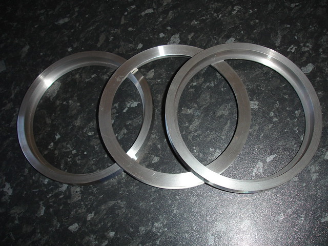 DSC00052 DSC00052 by reg.rossiter, on Flickr The wheels were mounted on a mandrel and held in place with an M10 Allen bolt. They were machined on the diameter to create an interference fit with the tyres of 0.006”. Before I took the final cuts I let the wheels cool down to room temperature as they were getting quite warm (0.020” cuts at 121RPM and a feed rate of 0.002” per rev). The front face was machined to allow for the front of the tyre which is 0.031” thick. The balance weights need to be level with the face of the tyre so I didn’t touch them.  DSC00046 DSC00046 by reg.rossiter, on Flickr To heat the tyres I just used the oven in the kitchen set to maximum. An hour seemed to be enough and I could see the colour change through the glass door as they heated up. They slipped on without any problem. One thing that happened was that as the tyre cooled down and got a grip of the wheel, the axle hole seemed to close up ever so slightly, not a lot but I could detect it as I removed the wheel. After the first tyre was fitted I then opted to remove the wheels from the mandrel as soon as the tyre got a grip just in case I got one jammed on. Machining the wheels and fitting the tyres took 10 hours.  DSC00048 DSC00048 by reg.rossiter, on Flickr The acid test is the subsequent machining of the tyres – hopefully they won’t slip on the wheels! I took 4 x 0.010” cuts off them all without problem so I reckon they should be good for the final profiling. 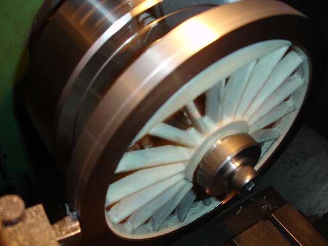 DSC00060 DSC00060 by reg.rossiter, on Flickr  DSC00064 DSC00064 by reg.rossiter, on Flickr Reg |
|
|
|
Post by Deleted on Oct 2, 2021 9:44:18 GMT
Excellent work Reg, very impressive sir...
Pete
|
|
|
|
Post by ettingtonliam on Oct 2, 2021 10:46:03 GMT
You noted that when you shrank on the tyre, the centre hole appeared to close up slightly. E A Langridge relates that when the Britannias were under investigation because of a spate of wheels moving on their axles, it was found that if the tyres were shrunk on after the wheels had been pressed on to the axles, the radial pressure at the wheel/axle interface was 56% greater than if the wheels were pressed on after the tyre had been shrunk on.
Apparently the balancing machine couldn't accomodate roller bearings which some of the Britannias were fitted with, and so balancing, which necessitated the tyre being in place, required the wheels, complete with tyres to be pressed on to a dummy axle for balancing, then pressed off, and pressed on to the proper axle, which had the roller bearings already fitted. This procedure reduced the final grip of the wheel on the axle and contributed to the wheel moving problem.
|
|