|
|
Post by terrier060 on Dec 26, 2018 20:22:25 GMT
Wonderful work Bob. I love all the love and detail that has gone into the cab platform -way over the detail level I am going to. I thought the injector picture was of the full size loco! I would love sometime to have some details of your injectors if you could spare them as I have some odd vertical ones to make for the Terriers.
A happy new year to you.
Ed
|
|
|
|
Post by 92220 on Dec 27, 2018 10:25:20 GMT
Hi Ed.
Thanks Ed. The cab platform is an exact copy of the fullsize. It was actually fairly easy to make. All the bits were machined on the mill to make sure they fitted perfectly. It was the jigging that took the time and thought, to make sure the assembly didn't buckle and distort with all the multiple silversolderings.
I'm afraid the injector photo wasn't mine though. I haven't got my injectors sorted yet. It was Don's (don9f) photo, but you are right. It does look very real!
Bob.
|
|
don9f
Statesman
 Les Warnett 9F, Martin Evans “Jinty”, a part built “Austin 7” and now a part built Springbok B1.
Posts: 960 
|
Post by don9f on Dec 27, 2018 11:09:37 GMT
Hi, the injectors in that photo were made by Gordon Chiverton and date from the 1980’s. I’m sorry but don’t really have any details other than that the “exhaust” injector is just a “live” one inside a dummy body, both having similar performance, so presumably having the same cones etc. I did partly dismantle the live steam one recently to clean it and there was a photo of the internal non return valves somewhere on this forum a while back....I’ll have a look but it might take a day or so due to other things happening etc.
Cheers Don
|
|
|
|
Post by terrier060 on Dec 27, 2018 11:53:42 GMT
Thanks Don - I would really appreciate that. I did wonder if anything was published in ME - drawing of cones etc. The ones on Fenchurch do not appear to be lifting, with no ball chamber. I wonder if anyone has built model ones without the ball valve? Perhaps this should be continued on my thread rather than clog up Bob's. I shall be very interested to see how you go about the injectors Bob.
Cheers Ed
|
|
|
|
Post by 92220 on Dec 27, 2018 12:29:52 GMT
Hi Ed.
As far as my injectors go, Adam is experimenting with injector cone cartridges. If that works out I shall fit his cartridges inside scale injector bodies.
Bob.
|
|
|
|
Post by 92220 on Dec 27, 2018 12:33:25 GMT
Hi Ed and Don.
I've just Googled Gordon Chiverton UK, and it appears that you can still get the Chiverton design injectors from Paviersteam.com, made for them by Len Steel. Looks like Polly Models also do them.
Bob.
|
|
|
|
Post by terrier060 on Dec 27, 2018 12:43:10 GMT
Many thanks Bob
|
|
|
|
Post by 92220 on Dec 28, 2018 10:46:33 GMT
Hi All.
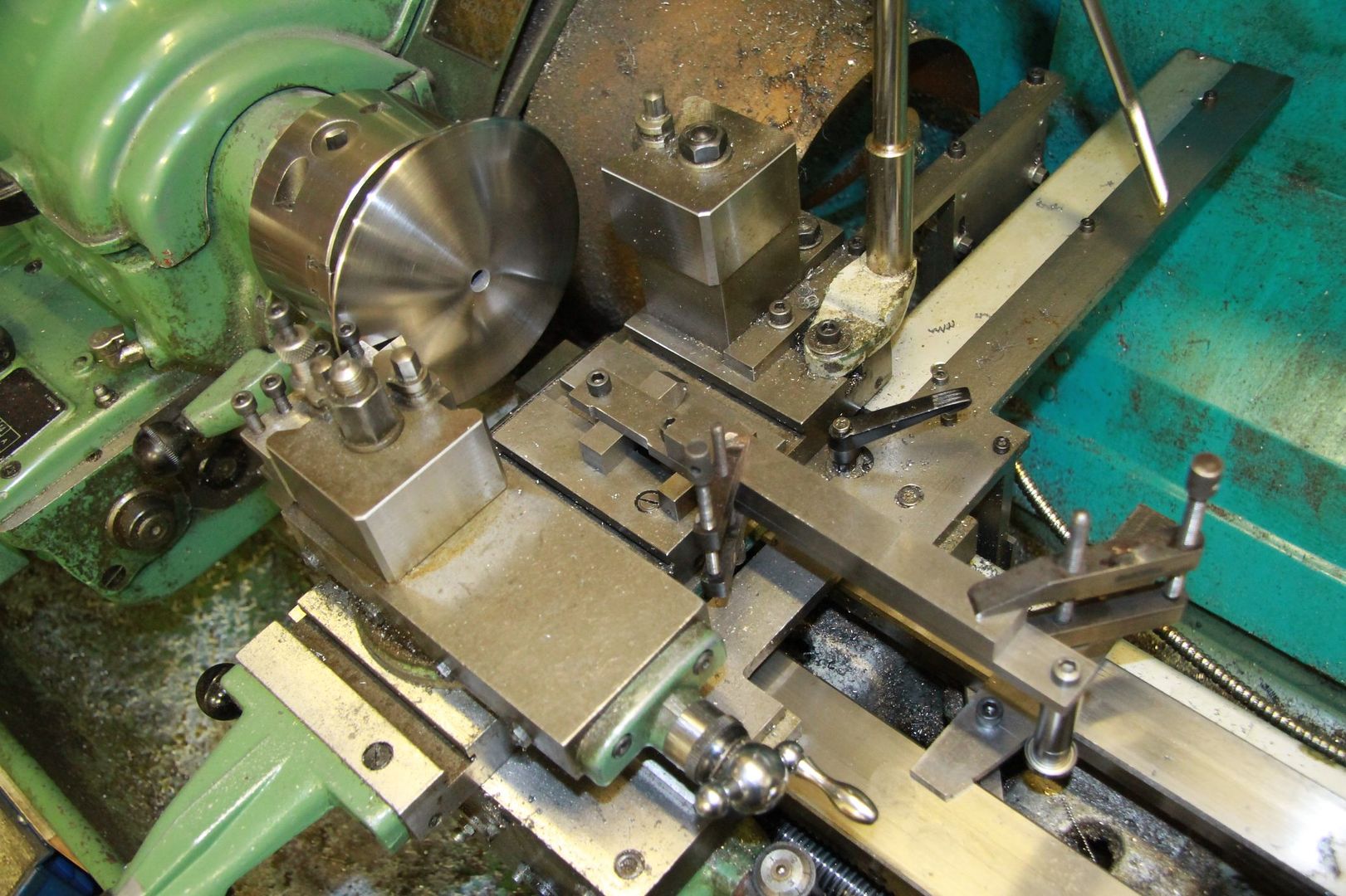
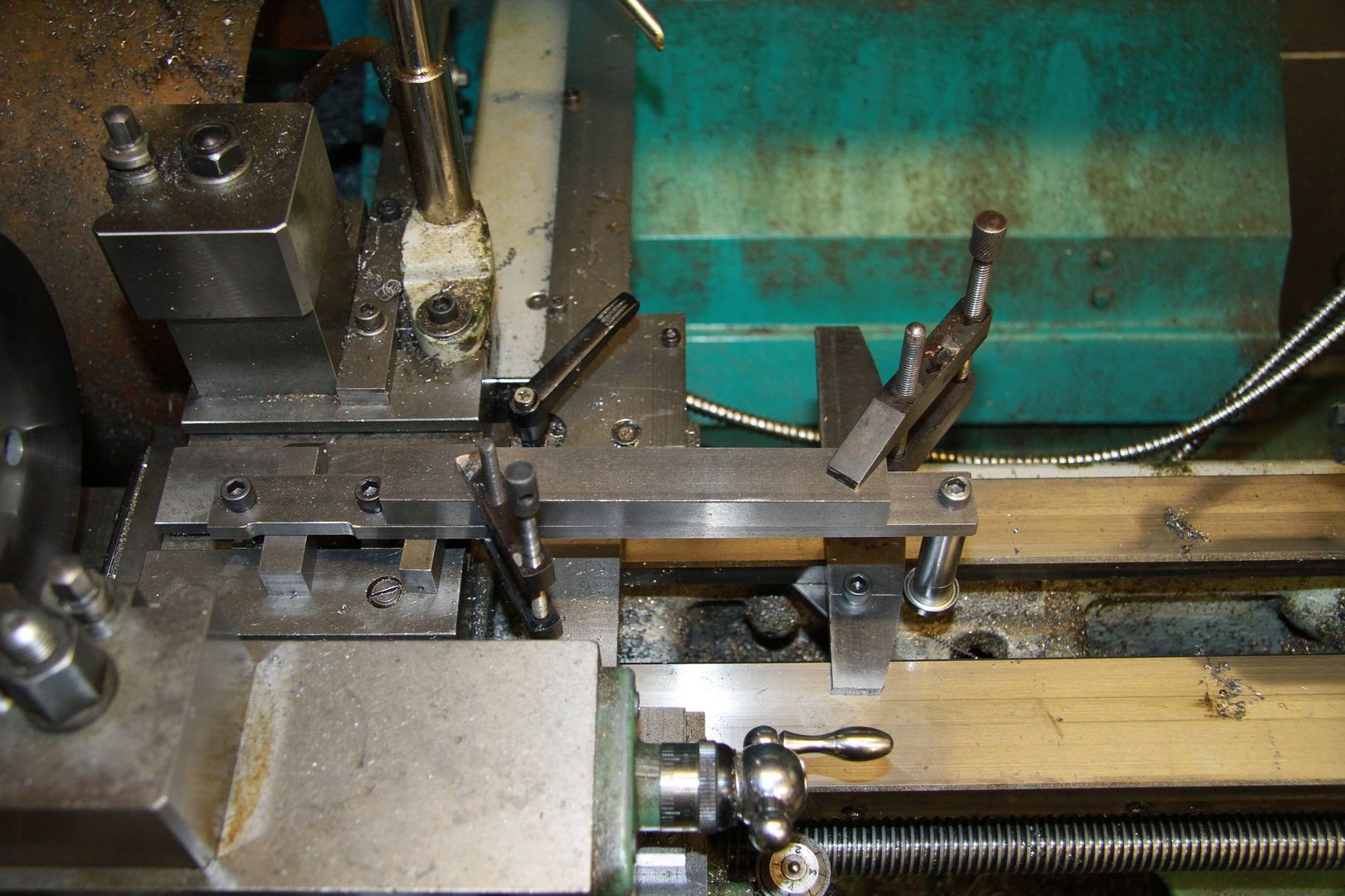
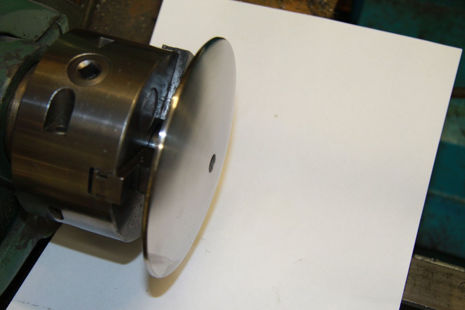
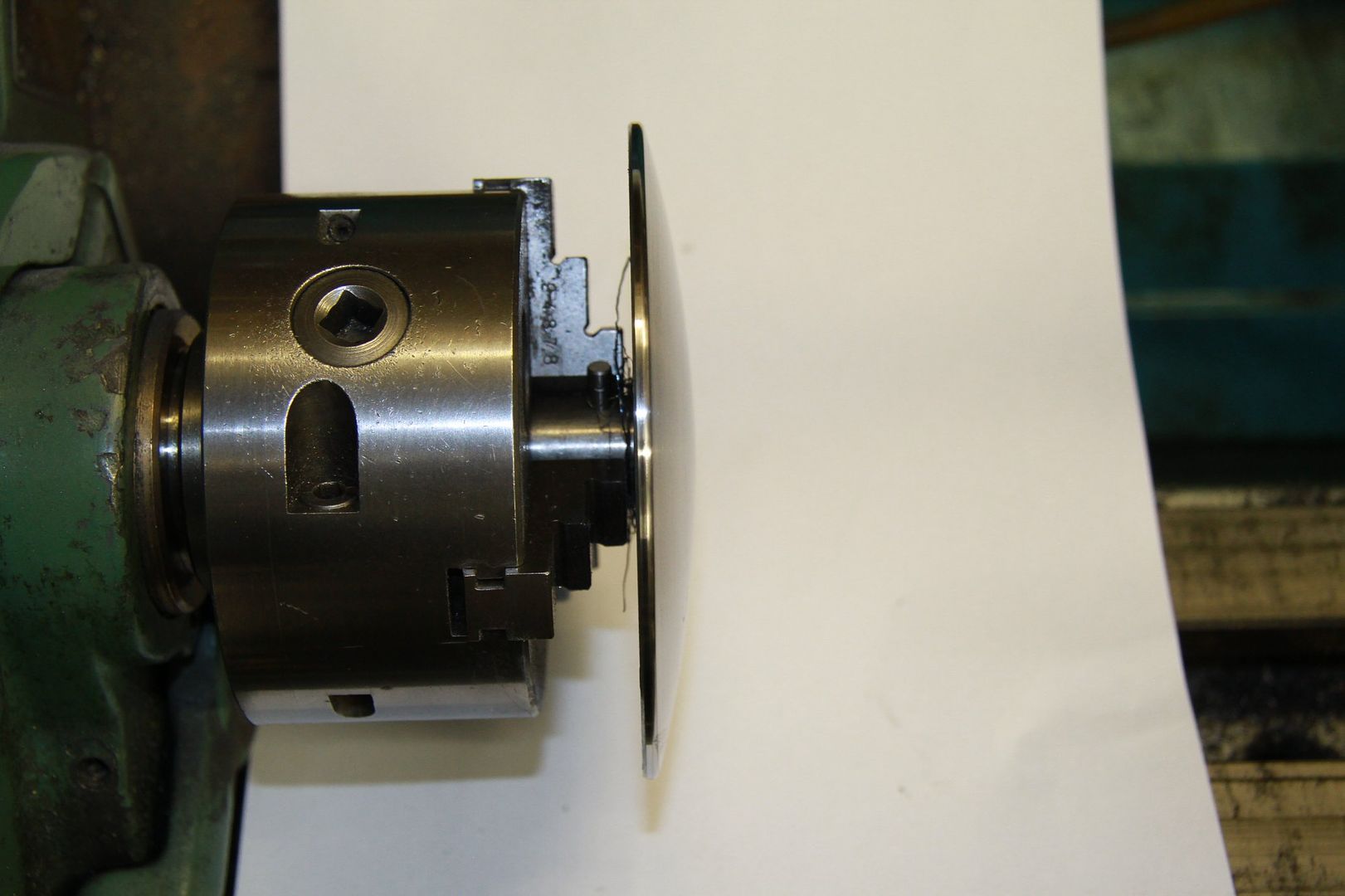
I said I would add the photos of the set-up for machining the smokebox door, so here they are:
First off I drilled and reamed a 1/2" dia hole in the middle of a square of 12mm mild steel plate. I them machined a 5.5" dia disc out of the middle of the steel plate, on the mill, with the 1/2" dia hole centred on the rotary table. I then turned up a stub arbour with a 3/8" UNC tapped hole in the stub, to mount the mild steel disc in the 3-jaw Griptru chuck. The arbour was held in the chuck and centred to within 0.0003" and then coated with Loctite 221 Threadlock. The mild steel disc was pushed on and checked that it was running true across the face. It was locked in place with a 3/8" UNC (or it might have been a BSW as they are interchangeable) and left overnight to set. The next job was to make a former for a probe, locked to the cross-sloide, to follow and pull the carriage along the bed.
This was done by tightly bolting a piece of 1/4" x 1.1/4" BMS flat, about 6" long, across the end of another 12" length of 1/4" x 1.1/4" BMS flat, to form a Tee. This was then clamped to the rotary table, which had already been centred under the quill of the mill. With a 6mm carbide endmill in the quill collet chuck, the mill table was would along so that the centre of the cutter was exactly set to a radius of 9.957" plus 3mm for the cutter radius. It was then would out another 0.05" and the table locked in X and Y.
A radius was then machined in the 1" x 1.1/4" x 6" BMS, at this radius, to produce a rough curved copying former. The radiused edge was then carefully machined down to exactly 9.957" radius. The machined edge was finished off with the side flutes to give a smooth surface to act as the copy face. Milling was not really quite good enough so the edge was polished with emery until it was perfectly smooth. Little clamps were then made so that it could be clamped to the lathe bed.
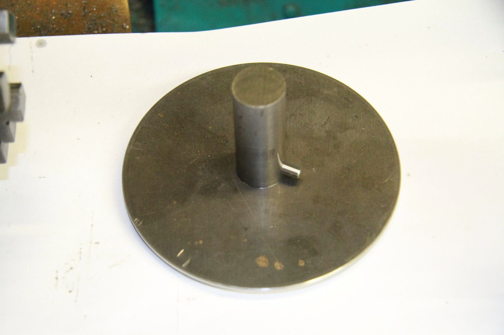
The arbour was drilled 3/16" dia towards the stub end, and a 3/16" steel pin was Loctited in place to act as a drive pin. "Why"? you may ask. Well at a radius of 2.75", and using a carbide cutter, there was likely to be quite a heavy twisting force on the chuck jaws, at a radius of only 1/2", as the arbour was made from 1" dia BMS bar. I didn't want to risk the arbour slipping in the chuck, as any slip would have moved the tool point away from the correct copy line.
The cutter was then used to just skim the end face of the head of the locking screw. This gave me the exact centre to line up the tool against, so that the curved copy former could also be set up exactly on the centre of the former-following ball race. The rear edge of the former also lined up square to the edge of the lathe bed, with an engineers square.
Then it was just a case of briong the tool to the outer edge of the BMS disc, wind the cross-slide out until the tool was in line with the edge of the BMS and then advance the topslide until the tool poiunt was just about to touch the disc. The lathe was started at around 150 rpm because of the large diameter, and the topslide advanced further until the tool just started cutting. A note was made of the DRO settings so that the tool could be brought back to exactly the same place after each cut, and then advanced with the topslide 0.005" each time. This is actually quite a deep cut for this job and every so often the tool pushed the carriage up the bed a few thou and the cut stopped. It was just a case of bring the cross-slide back and bring the ball race back into contact with the former, and start up again.
Once the door was almost to size and shape, the cut was reduced to 0.002" each time. This ensured the tool didn't get pushed away from the cut due to excessive depth of cut. Even so, the resulting machined surface was still not as good as needed. One last cut was to be made, and a new tool set up, with the cutting edge trailing instead of leading. That way there was a wider cutting edge and no chance of it digging in and spoiling the finish. Rotation was further reduced to around 100 rpm, and the topslide advanced for the tool to JUST touch. The power crosslide was engaged and coolant used on the tool edge. The tool took a minute cut all over the surface and left a reasonable finish.
The surface was still not good enough for painting so emery cloth was used to take the tool marks out. The inclination is to use a higher speed for this but that is NOT the way to go. You can take a lot more metal off with 120 grade emery at 100 rpm than you can at anything over that. I worked for just 30 minutes on the surface and it ended up exactly as I wanted it. There are what appear to be marks but they are so shallow that they can't be felt and will be invisible under even a thin coat of paint.
Here are the photos:
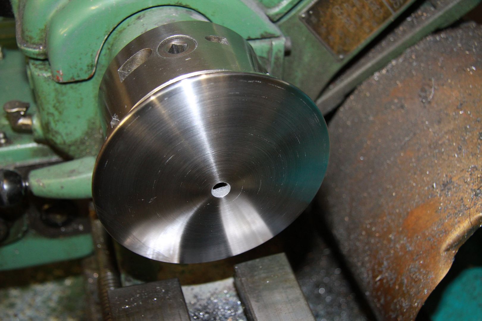
The next job is to machine the back of the door. This will be done exactly the same way, but with a concave former instead of the convex former.
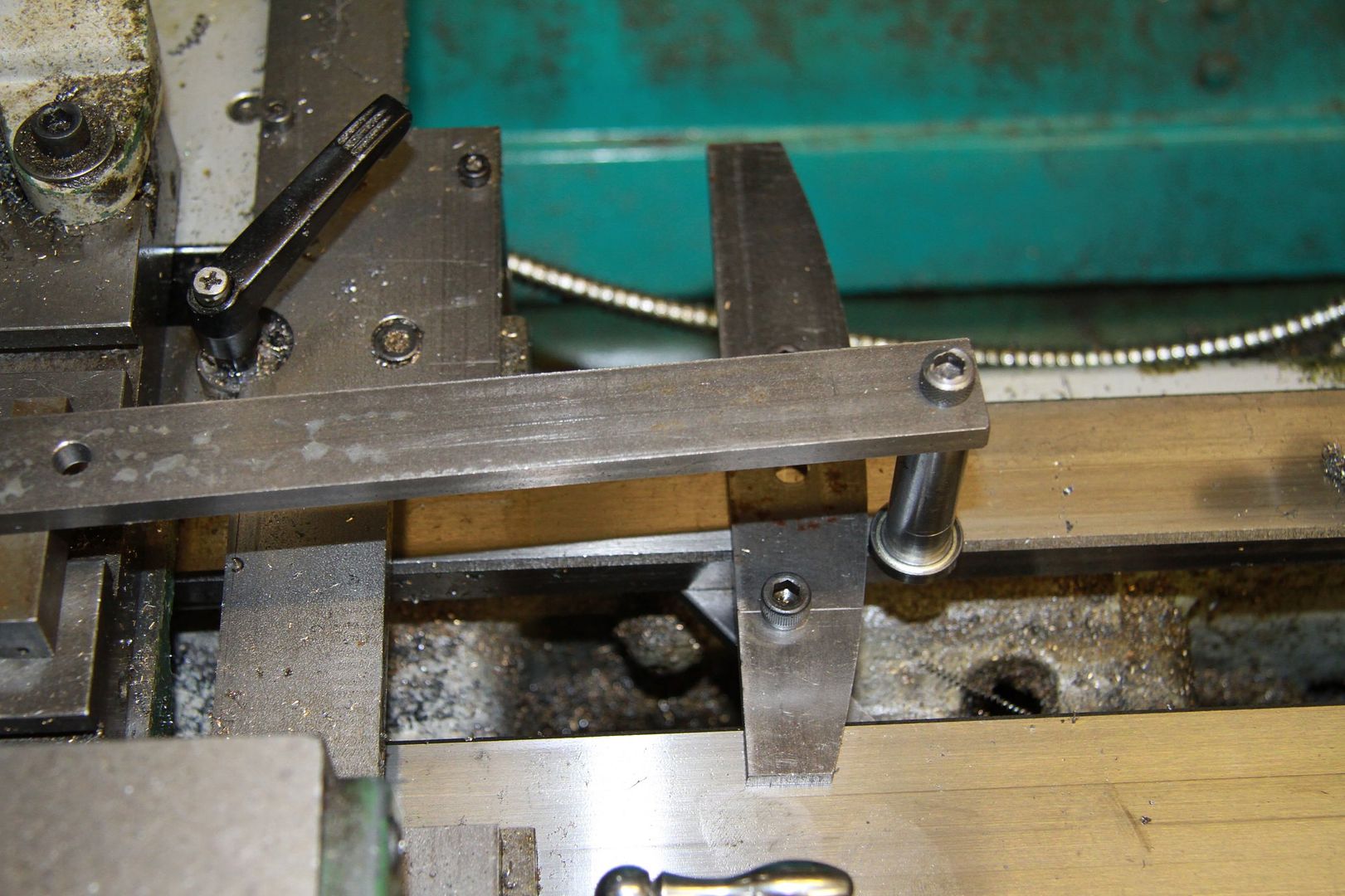
Edit: I forgot to add about the stiffener bar clamped to the top of the follower bar. I found, initially, that the follower ball race was moving out of it's intended path by a few thou. It was the follower mounting bar that was bending slightly, due to the fact that the ballrace was set quite a long way from the bar, so there was an increased moment about the mounting screws. The stiffening bar made all the difference. I had to raise it all up rather than clamp direct to the cross-slide, because the mounting bar had to be high enough to pass over the carriage locking ratchet lever. If it had been able to be clamped direct to the cross-slide, I think the machined finish would have been even better and not needed as much cleaning up with emery.
Bob.
|
|
|
|
Post by doubletop on Dec 28, 2018 23:01:49 GMT
Bob It is gratifying for me to see the experts coming up with a similar solution to my own. It reinforces to me that I’m begining to think the right way. Here’s the template I used for my Dart smokebox door.  I cut mine using the Smooth R function on the DRO’s on my mill. You probably realised that you only need half of the curve as the lathe does the other half. The block underneath is for clamping to my V bed lathe. I had similar problems to you with the bar bending and needing stiffening. Pete |
|
|
|
Post by 92220 on Dec 29, 2018 9:06:34 GMT
Hi Pete.
I made my former fully shaped because it was easier to do that than form a half shape. I needed the extra length to accommodate the clamp that clamped underneath the outer slideway underside. I could have just used a single clamp between the bedways but I didn't trust it not to move, so fitted 2 small clamps rather than the big one you have made up. Yours is a better job but I didn't want to bother making something that would only be used once.
I did say that to machine the back face of the door, I would use another former, concave in shape. Having just set up the lathe to do the machining, I realised that I use the same former. The difference in radius between the inner and outer surfaces is so small that using the same former makes sense.
Bob.
|
|
|
|
Post by David on Jan 1, 2019 11:03:35 GMT
It looks excellent - no surprise there!
I don't understand how to do this. Do you keep constant pressure on the saddle towards the chuck with the handwheel, relying on the former to not allow it to go further forwards than it should at any given location on the cross slide?
|
|
|
|
Post by 92220 on Jan 1, 2019 12:04:59 GMT
Hi David.
No. It's actually self controlling. As long as you always advance the crosslide so that the follower is forcing the saddle to move along the bed, the load required to move the saddle sideways, will always keep the follower against the shaped former that is clamped to the bed. Also, only take shallow cuts, no more than 0.005" deep, otherwise there is the risk of the cut forcing the cutter away from the correct tool path. This isn't a major problem, just annoying. The next cut will remove the excess left by the lifted tool. One thing to remember when you pull the tool back to start another cut....wind it away from the face being formed otherwise it will dig in. Make a note of the DRO or topslide thimble reading so that you can set the tool back to it's original position, plus whatever depth of cut you want (No mire than 0.005" deep). Hope that helps.
Bob.
|
|
dscott
Elder Statesman

Posts: 2,438
|
Post by dscott on Jan 2, 2019 1:03:52 GMT
Lovely to see this being made in the Temple to 9F itself.
Our own workshop is well insulated and can work in it most days Summer and Winter without any Condensation.
Filing buttons and copy lathes on the same principle? You can't take anymore metal off when you reach the required shape!
On the saddle of one lathe I have a 4 station stop capstan set when doing multiples. Now inspired Thoughts turn to mass
production of buffer sockets these are the BR ones with the ridge at the end. Bolt the profile in place and turn down to it!
Far too many times! Good use for my Gibraltar Tool post.
David and Lily.
|
|
dscott
Elder Statesman
Posts: 2,438
|
Post by dscott on Jan 2, 2019 1:11:18 GMT
I formed some smokebox doors for a Hunslet over some MDF Medium Density Fiberboard turned with another board with a hole and locating pegs. Put a sheet of steel in between and went in search of a local garage for a press!!
Smokebox doors anyone? Another use for my now Christmas Present!!
Thank you Bob.
David and Lily.
|
|
JonL
Elder Statesman
WWSME (Wiltshire)
Posts: 2,911
|
Post by JonL on Jan 2, 2019 11:20:01 GMT
Those hinges! I don't think I could even focus on them let alone build them!
|
|
|
|
Post by Deleted on Jan 2, 2019 11:27:54 GMT
Hi Bob Don't know if this is any good to you or not? but thought of you when I saw it posted on FB, it was dated 1974.. Anyway, it gives an unusual view of an injector and cab/tender area...i find when doing my own build that unusual photo's like this can yield hidden detail...hope it's of use...  regards Pete |
|
|
|
Post by David on Jan 5, 2019 1:28:42 GMT
Thanks, it makes sense now.
|
|
|
|
Post by 92220 on Jan 5, 2019 11:54:18 GMT
Hi Pete.
Thanks for the photo. It is an unusual one and very clear detail too.
Bob.
|
|
|
|
Post by 92220 on May 21, 2019 18:46:29 GMT
The smokebox is ready to fit in place. It's not finished in as much as there are no internals, such as the blast pipe, and exhaust pipes, so fitting is temporary. The boiler has also been temporarily fitted as well, so that the cab underframe and floor can be fitted. Fitting the boiler was a bit of a nightmare because it has mounting points in 4 places. First. The front of the boiler barrel fits into a ring on the back of the smokebox, that supports the front edge of the cladding. The next mounting is the front boiler barrel support that is screwed to a pad under the barrel and also to the first vertical stretcher. The next mounting point is the vertical stretcher that supports the 2 sliding feet that rest on it, just in front of the firebox, and supports the front of the firebox. Lastly, there are the 2 captive, sliding, rear firebox supports, that are bolted to the frames near just behind the firebox. It also had to end up placed so that there is a gap between the extreme rear or the boiler and the front edge of the cab floor, for boiler expansion. Much to my surprise, when I fitted the cab underframe in it's right place, on the frames, there is about a 6mm gap between the face of the backhead and the front of the cab floor, which is about right. Here is how the front of the smokebox was made :- Once the door was finished, as previously described, the next job was to machine the 'Protection Plate that fits on the back of the door Liner Plate. The Protection Plate is a thin plate that is riveted to the lower half of the door liner plate, and has an angled lower section. I puzzled over how to make this and it was a toss-up between making a press tool to form it in mild steel sheet, or machine it from solid. I would have had to buy metal to make the press tool, so decided to machine it from a disc of mild steel that I had in the scrap bin. It actually worked out quite easy to machine. I turned up the outside diameter and the outside of the angled face, and while it was on the lathe, a central hole, 3/8" diam was reamed, for setting up on the rotary table. The rotary table was set up concentric with the quill spindle, on the mill. The Protection Plate disc was then bolted to the rotary table, and centralised by holding a 3/8" dia piece of silver steel in a collet in the quill taper. The quill was set over at an angle of 18.5 degrees to match the outside angle that had been machined on the lathe. The finished door and front ring: 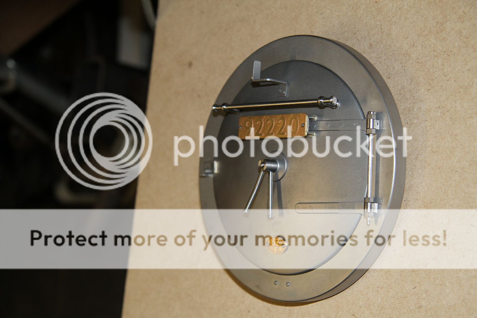  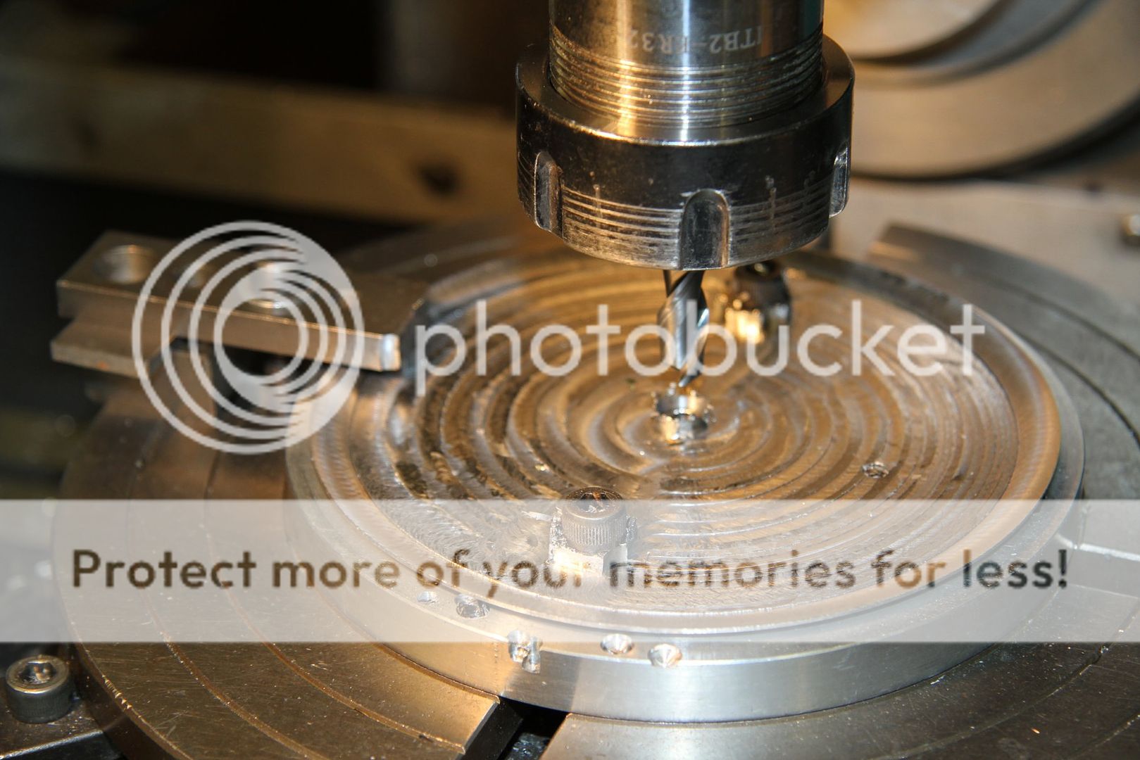  The door had already been made so the next parts were the door handles. The square hole in the boss was made by turning up a ring to the outside dimensions, with a hole through the middle of the same diameter as the width across flats, which was 0.111" a/f . The ring was then set up in the machine vice on the mill and the table adjusted to bring the ring central under the quill. A slot was then milled across one side of the ring to 0.111" width and to JUST clean up the trace of the drilled hole at the bottom and the milled slot. A piece of mild steel was then machined up to be a push fit in the milled slot. It was then machined to a few thou wider than the thickness of the ring and cut to a length that was slightly larger than the finished radius. It was then fluxed and pushed into the milled slot, against a steel rod machined to 0.111" dia. to form a square hole. It was then silversoldered. A mild steel mandrel was turned up, to be a slide fit in the square hole and threaded 6BA on the end, for a locking nut. The silversoldered ring was then clamped onto the mandrel with a 6BA nut and washer, and the O.D. turned to size. It was then set up in the 3-jaw chuck and one face was tidied up. The ring was reversed in the chuck and the other face cleaned up to get it to the required thickness. I then machined up a piece of mild steel rod, square, to just fit in the square hole, and about 3 times the length of the ring width. This square was used to locate the ring in the machine vice with the square hole parallel to the machine table. The quill was then centred over the ring and a 7BA hole tapped in it for the rods that made up the handles. These were turned up and threaded and then fixed in with Loctite. I forgot. Obviously the other ring was a simple ring with a tapped hole instead of a square hole.    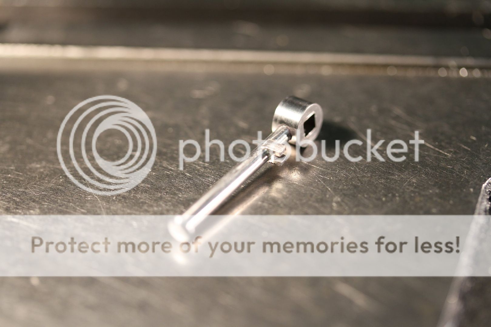 The central door boss has a pin in it to stoip the inside handle rotating when the door handles are used to close the door tight.  The smokebox rings were pushed into the ends of the smokebox tube and set up on the mill to drill through the holes for the 1/16" rivets. A couple of discs of MDF were turned up un the lathe, to be a tight push fit in the end rings, with centre holes drilled in each disc for the dividing head tailstock support. The smokebox tube was then set up on the mill and the table adjusted to bring the centreline of the smokebox tube in line with the centreline of the quill, and the door hinges vertical. 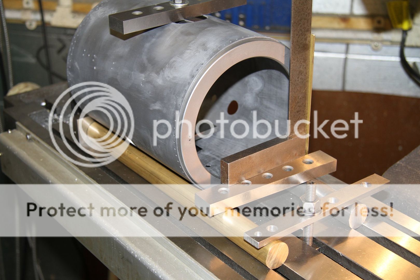 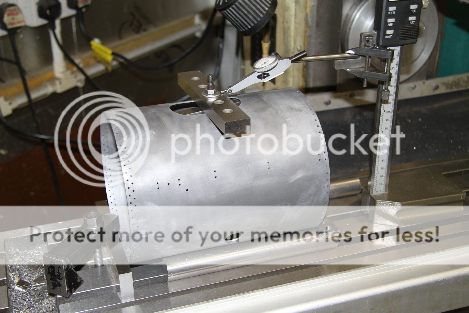 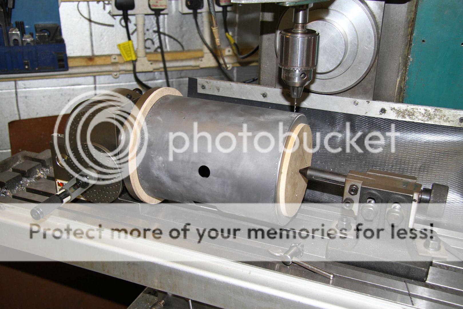 More to follow. I've got to upload the other photos to Photobucket. |
|
|
|
Post by Roger on May 22, 2019 8:10:48 GMT
Lovely work as always with excellent setups making sure it's all spot on. Glad to see you're making good progress.
|
|


