|
|
Post by terrier060 on Apr 9, 2021 22:24:38 GMT
Apparently the lubrcators came ready-made from steam fittings. Does this help establishing quality?
|
|
|
|
Post by coniston on Apr 11, 2021 22:38:56 GMT
I had to replace the sprag clutches in my Simplex lubricator as it was slipping (not long after I bought the loco which had many years running under it's belt by then) The ones I bought were not cheap (IIRC about £8 each) and they have lasted so far 3 years of regular running with no problems, so I guess it does pay to buy good ones. I have also recently fitted two Steam Fittings lubricators to my B1, not run them yet so cannot say about their quality / performance but the shafts are certainly hard and the clutches a good press fit in the housings so as long as the clutches are good then they should last ok. The other thing that people mention is not to allow the lubricating oil to get into the clutches, although on my Simplex they are in direct contact with the oil and so far no issues.
Chris D
|
|
|
|
Post by terrier060 on Apr 12, 2021 12:29:45 GMT
I have made some cones to Brown's design using a No 75 hole and this gives quite a good suction on my finger using compressed air, much better than before, so I am hopeful. I use the hand wheel on the Myford tailstock, and even with a No75 drill I still get feedback and can tell when the drill is biting, before it starts to bend! I have just bought the same clutches as you Chris - so that is good news! I had a job getting the old ones out of the casting, but machined them out. I do not like the very small bearing surface on the lubricators, so I am modifying them by extending the shaft across the tank to a trunnion on the other side. I am going to use a couple of the old needle roller clutches in there for extra grip on the shaft. Below is the Fusion simulation, so I will set them up on the Tormach. Click on the picture and it should run.  New ejector cones No75 drill New ejector cones No75 drill by ed cloutman, on Flickr  2021-04-12 11-11-37 2021-04-12 11-11-37 by ed cloutman, on Flickr |
|
|
|
Post by coniston on Apr 12, 2021 21:05:21 GMT
That's an good idea to support the shaft both ends, I'll have to have a look to see if I can do something similar.
Chris
|
|
|
|
Post by terrier060 on Apr 13, 2021 0:10:51 GMT
Hi Chris - I will post the modifications as I do them. Today I made the trunnions on the Tormach. I am waiting for the shaft to arrive (4mm diam silver steel), and the new clutches. The old clutches are a light push-fit in the trunnions. I think the originals are far too tight a fit and were a bugger to get apart. They do not need to be that tight as the load on them is not great.  Lubricator trunnions Lubricator trunnions by ed cloutman, on Flickr |
|
|
|
Post by steamer5 on Apr 13, 2021 2:30:54 GMT
Hi Ed,
The roller clutches do need to be a press fit. How much I can’t remember...somebody here will....or you should get the info with them.
The trunnions look great.
Cheers Kerrin
|
|
|
|
Post by 92220 on Apr 13, 2021 8:11:11 GMT
0.0010"/0.0015" interference should do, but what I did was make my roller clutches a nice slide fit and used a single drop of Loctite Threadlock 222 to lock in place. Just starting the clutch into the hole, and then applying the tiny spot of Loctite, ensured that none could get inside the clutch. Make sure the Loctite is all around the clutch body. I used 222 because the clutches are held tight but if necessary, can be pressed out without too much trouble. 222 is designed to allow screw threads to be undone with moderate effort.
Bob.
Edit. For industrial uses, the clutches would have to be pressed in with the manufacturers recommended interference fit, but for our use, the clutch should work fine in a slide fit hole and Loctite.
|
|
|
|
Post by Roger on Apr 13, 2021 8:53:29 GMT
0.0010"/0.0015" interference should do, but what I did was make my roller clutches a nice slide fit and used a single drop of Loctite Threadlock 222 to lock in place. Just starting the clutch into the hole, and then applying the tiny spot of Loctite, ensured that none could get inside the clutch. Make sure the Loctite is all around the clutch body. I used 222 because the clutches are held tight but if necessary, can be pressed out without too much trouble. 222 is designed to allow screw threads to be undone with moderate effort. Bob. Edit. For industrial uses, the clutches would have to be pressed in with the manufacturers recommended interference fit, but for our use, the clutch should work fine in a slide fit hole and Loctite. I agree with Bob on this, although I'd say that a thou is a lot of interference on such a small diameter. I'd go for half that personally as a maximum and a slide fit is almost certainly not going to be an issue. |
|
|
|
Post by terrier060 on Apr 13, 2021 16:51:04 GMT
Hi both - I found half a thou quite enough and you can see the modification below. I think all the Loctite would have been squeezed off with that tight a fit Bob, and unnecessary. Using Loctite requires some space if I remember correctly. I glued by cranks with it and they were a very light hand push fit. In fact they could be turned until the glue went off. That is how I did the quartering. Sorry Bob - I have just read your post more carefully and see that you did what I did and made them a nice push-fit for the Loctite! I also made a bronze spacer washer for the lubricator, to go between the lubricator body and the cam. 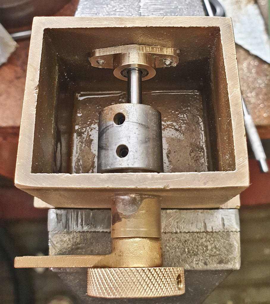 Lubricator mods Lubricator mods by ed cloutman, on Flickr |
|
|
|
Post by coniston on Apr 13, 2021 20:44:32 GMT
That looks pretty neat Ed, well done. Mine look a bit different to yours as the operating cam is actually a pin in a disc that rubs on and pushes down the piston plunger. I think i may scrap that and us a cam as yours is, it will I am sure be a better solution.
Chris
|
|
|
|
Post by terrier060 on Apr 13, 2021 21:53:16 GMT
Would you like a picture with the cam removed Chris?
|
|
|
|
Post by coniston on Apr 14, 2021 20:11:01 GMT
Would you like a picture with the cam removed Chris? If you can please Ed, that would be most helpful. Thanks Chris |
|
|
|
Post by terrier060 on Apr 15, 2021 18:23:42 GMT
Had a really good day today. I tried to capture the yellow sulphurous fumes from the chimney of the good Welsh steam coal, but missed the best bit. I will try again with my camera rather than the phone. The injector worked today, but was very sensitive to water adjustment. But it did run dry and give the characteristic cheeping noise. It definitely needs some refining though, and a test boiler would help. I set the steam cone, which is end regulated, to zero, and then tried it with a 10 thou and then an 18 thou shim. They both worked, but with the steam valve open fully I am having to turn the water down a long way before it picks up. I feel sure it should be able to cope with a much larger volume of water than it does at present. Still at least it worked which surprised me! The new ejector cones did not work at all until I realised the brake valve appears to be leaking. When I held it together it gave a reading of -14 ins/Hg, so getting better! The cylinder lubricators are working well with the new clutches - I am glad to say - very relieved. Underneath the cam is a flat-topped cap on the top of the ram with a spring beneath. I have moved the cam to one-side in the photo to show it. The 3D dial gauge is great for setting up bar stock accurately and quickly underneath the spindle. I just lower the Z axis until there is a dial reading when the ball is in the centre hole and then move the X and Y axes to give the lowest reading.  Steamup 15th April 2021 Steamup 15th April 2021 by ed cloutman, on Flickr |
|
|
|
Post by Roger on Apr 15, 2021 20:50:54 GMT
Great progress, the lubricator is a huge improvement on the original design. I don't know that they were thinking of, using such a short bearing arrangement with a large overhang. It's quite possible that the clutch issues were due in some part to the arm being at an angle to the shaft which must have tipped over when pressing against the spring.
I've had a long chat with Ed about today's Injector experiments, but thought it was worth sharing my Injector conclusions and reasoning here too, as that might be useful to others.
Assuming that the various throat sizes are correct, the only adjustment that can be made is with the Regulation Gap. The fact that it would run dry with both 10 thou and 18 thou shims but only with the water valve closed indicates that the Regulation Gap was too large for both of those. Basically, you're having to compensate for there being too much flow through the gap by restricting it upstream. You normally only have to do this when the pressure drops. If you need to restrict the water at maximum Steam pressure, there's too much water getting through, so you need to restrict it by reducing the gap.
What you're aiming for is the smallest gap consistent with a dry overflow at maximum pressure and with the water at whatever you deem to be a reasonable temperature. A gap larger than this may still give a dry overflow, but it will drop out sooner as the pressure drops than it would with a smaller gap. However, it will work with slightly warmer water.
If you want it to work with much warmer water, the gap will have to be progressively larger to allow more water through. That's because you need more warm water to condense the same amount of Steam. Even so, because the Injector is designed with a relatively low expected water temperature, you will get some water at the overflow when using hot water, even with an increased gap. An Injector designed for hot water will have slightly different throat diameters to match the Steam volume required for a given volume of hot water.
Hopefully that makes sense.
|
|
|
|
Post by coniston on Apr 15, 2021 22:45:50 GMT
Excellent progress Ed, you must be pleased. The phot of the cam and piston is perfect, I can easily make a cam to replace the pin arrangement and it should improve the smoothness of it working, thanks for that.
Chris
|
|
|
|
Post by terrier060 on Apr 15, 2021 23:03:23 GMT
Great Chris - as Roger says, the mod makes mechanical sense and a much more robust arrangement than the original.
Regarding the injectors, it is very satisfying seeing one you have made yourself actually working, all be it requiring quite a lot of tweaking! This is where a test boiler in the workshop would be useful, as Roger has shown. However it is very simple to make up a series of shims and only takes a few minutes to swap the injectors on the actual loco. The drawing for the injector is on my page 52. I will make one for the other side if I get this one working to my satisfaction. On Saturday I will start with a 4 thou sim and work in thou up to 10, which is where I started today. It seems that the regulation gap is by far the most critical item to get right. I do like end regulation because it proves it can work on a conventional injector and does away with that fine nozzle which has the tendency to wear away, or get easily damaged.
I should add that although my injector is the usual 4-cone type, I have learned a lot through Roger's research, and dialogue over the telephone.
Ed
|
|
|
|
Post by terrier060 on Apr 27, 2021 23:40:20 GMT
My friend with the steam launch has a Weir pump which has a steam cylinder at one end and water pump at the other. It is a horizontal engine.
The piston rings on the water pump appear to be made of some rubber - called something like lignumite?? Could anyone suggest a modern material to make new rings from?
|
|
|
|
Post by RGR 60130 on Apr 28, 2021 7:29:32 GMT
My friend with the steam launch has a Weir pump which has a steam cylinder at one end and water pump at the other. It is a horizontal engine. The piston rings on the water pump appear to be made of some rubber - called something like lignumite?? Could anyone suggest a modern material to make new rings from? I found this company which produce composite piston rings. www.elektro-isola.com/components/mechanical/piston-rings?gclid=EAIaIQobChMIiJmI7bKg8AIVDdxRCh2ZagNFEAMYAiAAEgJsgPD_BwEI'd imagine in your friend's case the feed water will be cool so that might make material selection easier. Reg |
|
|
|
Post by Roger on Apr 28, 2021 8:32:09 GMT
My friend with the steam launch has a Weir pump which has a steam cylinder at one end and water pump at the other. It is a horizontal engine. The piston rings on the water pump appear to be made of some rubber - called something like lignumite?? Could anyone suggest a modern material to make new rings from? To be honest, without a picture or drawing of what the rings look like, it's hard to know what to suggest. |
|
|
|
Post by terrier060 on Apr 30, 2021 21:53:42 GMT
Thanks both. Will try and get some pictures. As far as I know they are just straight rings. Nothing special.
|
|


