rrmrd66
Part of the e-furniture

Posts: 339 
|
Post by rrmrd66 on Nov 25, 2017 14:24:33 GMT
Hello Everybody. Has anybody got a copy of Model Engineers Workshop Issue 136 March 2008 with details about the between centres boring bar by Paul Murton? If so would it be possible to scan or whatever to give me a copy. Maybe by a PM? ( Not too certain how that works). I fancy making one in preparation for the machining of the cylinders for my 5" gauge Hunslet Engine. Many Thanks Malcolm ![]() |
|
|
|
Post by springcrocus on Nov 25, 2017 16:49:56 GMT
Hello Everybody. Has anybody got a copy of Model Engineers Workshop Issue 136 March 2008 with details about the between centres boring bar by Paul Murton? If so would it be possible to scan or whatever to give me a copy. Maybe by a PM? ( Not too certain how that works). I fancy making one in preparation for the machining of the cylinders for my 5" gauge Hunslet Engine. Many Thanks Malcolm ![]() Why don't you have a look on here, Malcolm? There is my own thread on between-centres boring bars on page 3 of this section, which includes an interesting contribution from Jason B. Also, Lisa recenty described her boring bars in her Blowfly thread. There should be enough material to get you going, I hope. Regards, Steve |
|
rrmrd66
Part of the e-furniture
Posts: 339
|
Post by rrmrd66 on Nov 26, 2017 7:41:57 GMT
Hi Steve
Thanks for the tip.
Still wouldn't mind that MEW article though.
Regards
Malcolm
|
|
rrmrd66
Part of the e-furniture
Posts: 339
|
Post by rrmrd66 on Nov 26, 2017 19:30:50 GMT
Hello again Steve
Hi Steve (and Lisa)
I have had a good read through your post and that of Lisa's
All good stuff. It was detail of the indexable tool setting screw I was after. Is it 40 tpi x 50 graduations?
Somewhere in Lisa's post (I think) I was diverted to a "mrcrispin" on You tube. Have you seen this? Well worth a look.
Cheers
Malcolm
|
|
|
|
Post by goldstar31 on Nov 28, 2017 8:39:58 GMT
Model Engineers Workshop Manual by G H Thomas has the words and music about angles and threads.
|
|
rrmrd66
Part of the e-furniture
Posts: 339
|
Post by rrmrd66 on Nov 29, 2017 8:09:58 GMT
Thanks for the tip Goldstar.
By a strange freak of coincidence it is on my Christmas wish list to Santa Claus in the far north (daughter in Newcastle upon Tyne).
Cheers
Malcolm
|
|
|
|
Post by goldstar31 on Nov 29, 2017 10:44:40 GMT
Thanks for the tip Goldstar. By a strange freak of coincidence it is on my Christmas wish list to Santa Claus in the far north (daughter in Newcastle upon Tyne). Cheers Malcolm Laughingly, the book was edited by a dental surgeon in Chester le Street ( or Darlington) but he did his training in Newcastle- when Kings College was part of Durham Uni! I married his classmate! Whatever, it's a good read so I hope that your book is in Santa's Bag. Enjoy! Norman in the wilds of Gosforth NE3 |
|
rrmrd66
Part of the e-furniture
Posts: 339
|
Post by rrmrd66 on Nov 29, 2017 12:35:29 GMT
Well blow me down, Norman.
Daughter is in NE7
You could be neighbors,almost!
Best Wishes
Malcolm from sleety (at present) Thirsk YO7
|
|
|
|
Post by springcrocus on Nov 30, 2017 19:56:37 GMT
My post was slightly off-topic and was confusing the issue so I have removed the content. Sorry, guys
Regards, Steve
|
|
|
|
Post by goldstar31 on Nov 30, 2017 20:36:13 GMT
Let's settle for 25 divisions please- unless you want funny sizes
|
|
|
|
Post by goldstar31 on Nov 30, 2017 22:23:38 GMT
I'm on 40TPI which is the ME fine ME thread.
Is there a 25 or 50TPI normal tap and die set?
Nah then whatcher say about BA which is metric.?Not exact but nigh enough for pit work.!
Regards
N
|
|
isc
Statesman
Posts: 708
|
Post by isc on Dec 1, 2017 9:07:37 GMT
40 TPI is the thread used for an imperial micrometer, 0.025" per turn.
isc
|
|
|
|
Post by goldstar31 on Dec 1, 2017 10:27:09 GMT
40 TPI is the thread used for an imperial micrometer, 0.025" per turn. isc Agreed but respectfully it may be prudent to read up what was said- at the time about making a calibrated boring head. There is a remarkably well argued case for not using a 40 tpi screw at 90 degrees nor one at 45 but if my memory isn't too fugitive -40 degrees which I suspect mine is-- somewhere. The other recommendation - again, I am going on all our yesterdays using a more commonly( then) British Association tap which had a thread of 25.4 inches which sort of allows a crude indicator of 40 divisions- and NOT 25 which is obtained from the 40TPI Model Engineers fine thread. Of course, this was almost the time of the Dodo ( and the ubiquitous ouzel woozel bird) and go Metric and one of my projects calls for nothing more elaborate than a 3 mm bit of studding as a feed screw to a tool and cutter grinder. I'll get my coat! Norm |
|
|
|
Post by houstonceng on Dec 2, 2017 13:37:12 GMT
Malcolm
Do you still want a scan of the MEW article, if so, PM me with your e-mail address and i’ll Pop up to my Archive copies and scan it for you.
|
|
|
|
Post by houstonceng on Dec 2, 2017 13:37:23 GMT
Deleted duplicate
|
|
Lisa
Statesman
Posts: 806 
|
Post by Lisa on Dec 6, 2017 8:57:07 GMT
I missed this, but my boring bars use metric threads for the indexing screw, and at 90°: M8x1.0, so ¼ of a turn = 0.25mm cut.
|
|
rrmrd66
Part of the e-furniture
Posts: 339
|
Post by rrmrd66 on Dec 7, 2017 19:12:44 GMT
Thanks for this Lisa.
I think I prefer the 45deg tool bore. This will make measurement with a "mic" more precise as the anvil, on the non tool side of the bar, has a perfect cylindrical surface to register against.
None the less thanks to all the above people for lots of good tips and showing interest.
I think that this will be a good project to christen my "new" (1976) Harrison M400 with.....that is when I have removed 40 years worth of swarf/oil/dust but fortunately no rust.
Cheers
Malcolm
|
|
Lisa
Statesman
Posts: 806
|
Post by Lisa on Dec 7, 2017 20:05:26 GMT
Thanks for this Lisa. I think I prefer the 45deg tool bore. This will make measurement with a "mic" more precise as the anvil, on the non tool side of the bar, has a perfect cylindrical surface to register against. With 90°, I just used a dti on the tool when adjusting, for the last few cuts anyway; most cuts to get the bore up to size were thoroughly guesstimated. |
|
|
|
Post by Deleted on Dec 9, 2017 23:31:39 GMT
When I made my boring bar which I have just been using as most will know I set my bit at an angle...not 45 degrees though....I forgot to include this in my right ups but I set the tool at an angle so it was a fraction ahead of the collar fitted to the bar. My reasoning was that as I had a blind bore I could use the collar as a stop...I have to say it worked very well....  Pete |
|
rrmrd66
Part of the e-furniture
Posts: 339
|
Post by rrmrd66 on May 10, 2018 18:42:50 GMT
Evening all. WARNING Some viewers may find the following post contains unsuitable images (especially the CAD brigade)  Thank you to all those that made suggestions and sent copies of articles on to how to make a between centres boring bar. I thought you might like to see my attempt. More details about what I was boring can be found in my post on the 5" gauge Hunslet build (not yet updated). I received a copy of George H Thomas's book The Model Engineers Workshop Manual from Santa Claus and I have stolen most of my design from him. First, here is my sketch done with pencil and 6" rule to get me going. Ignore the note about clarity. All the bores are in the same plane. The M5 dog point screw is for locking the tool and the M8 is for advancing it. For those that like formulae the actual cutting diameter is: Micrometer measurement over tool tip - 0.5" x 2. I was aiming for 1.625" dia. 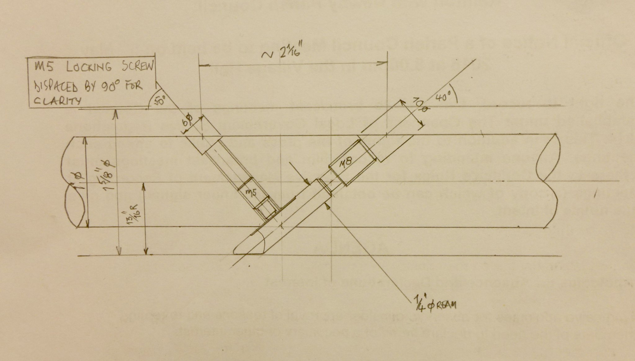 fullsizeoutput_6af fullsizeoutput_6af by Malcolm HARWOOD, on Flickr I decided to make two bars from 1" dia MS bar x300mm length. One bar was for roughing out, the second for the final cut. The plan was to put bar No2 into play at the last moment and do the same on the second cylinder boring thereby getting two similar cylinder bore dimensions. Here I am boring the 1/4" dia. hole to accept the 1/4" dia HSS tool. The bore was hand reamed to 1/4". My good friend Peter ( he who gave me his Harrison 300) also gave me an interesting tilting table and said that it would come in useful. How right he was. I fiddled about with the full tilting head on the milling machine but gave up for a variety of reasons. I will update the saga of the Warco Super Major miller in due course. Note that I had hand sawn some knicks in the bars so that a flat face was presented to the drill. I also spot faced them with an end mill to tidy them up. Apologies again to the purists for the oak straps but I found that the tapped holes in the tilting table were 5/16" BSF. Fortunately I had 4 long bolts in a tin (like you do) and needs must. 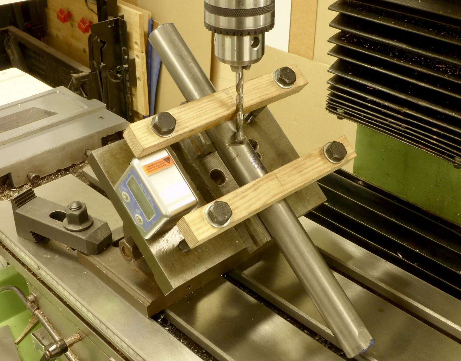 fullsizeoutput_6b3 fullsizeoutput_6b3 by Malcolm HARWOOD, on Flickr I then counter bored this and tapped it for the M8 thread 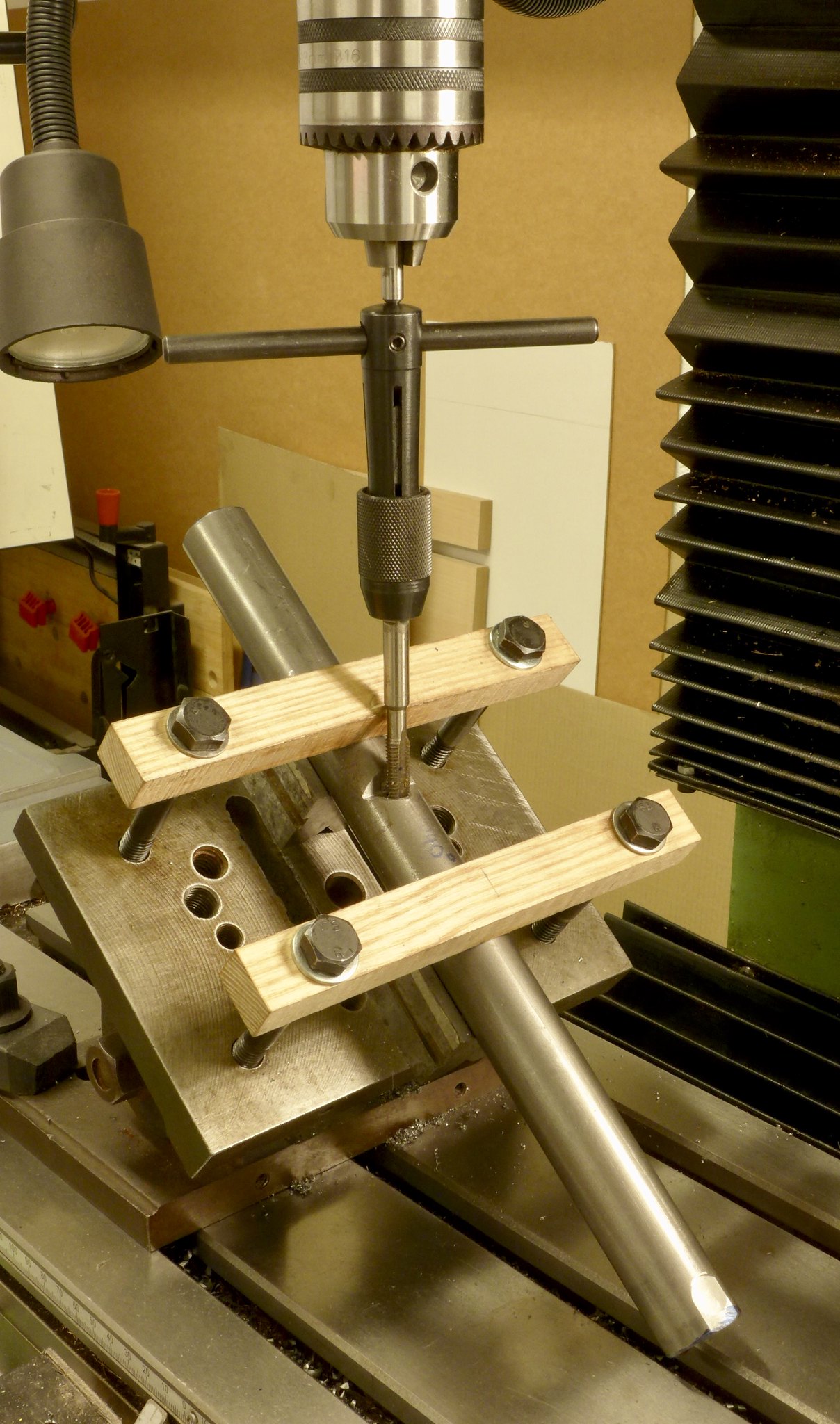 fullsizeoutput_6b5 fullsizeoutput_6b5 by Malcolm HARWOOD, on Flickr Next I had to rearrange the bar for the M5 screw due to the "steep" 50deg angle and to clear to chuck. 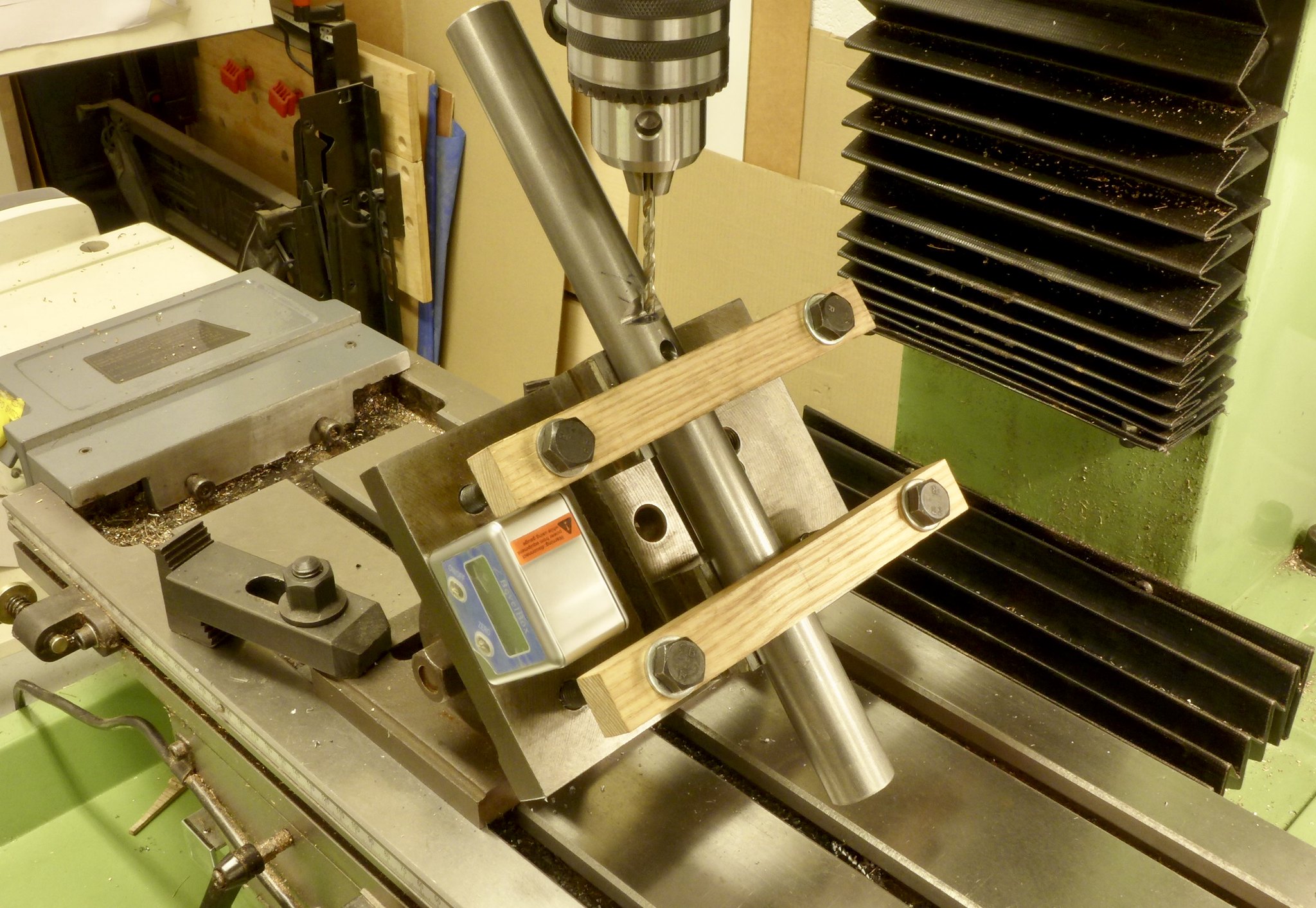 fullsizeoutput_6b1 fullsizeoutput_6b1 by Malcolm HARWOOD, on Flickr Finally I had two bars. Note that I have marked the finish size bar to avoid confusion. The HSS tool is a bit of a pain as one has to remember that the tool is inclined at 40deg to the axis of the bar so that there has to be lots of relief. Also it is advisable to grind a flat for the M5 dog point to bear against and stop the tool rotating in its bore whilst boring the cylinders. 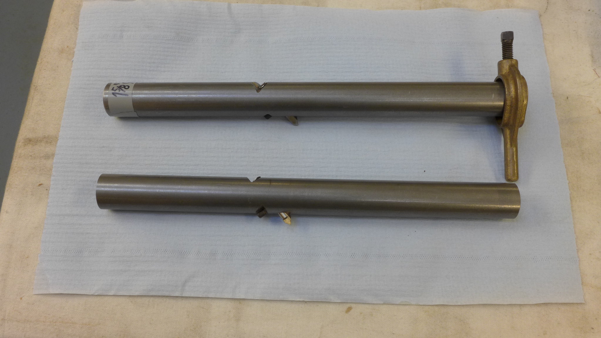 P1010277 P1010277 by Malcolm HARWOOD, on Flickr Finally this was the set up and a sneak preview of the actual cylinders. More will be revealed in the Hunslet Build thread shortly. Suffice to say that the Myford vertical milling slide is not quite what it should be due to the fact that it is heavily cantilevered and likes to go for a "spin"!  P1010276 P1010276 by Malcolm HARWOOD, on Flickr Hope you found this interesting and thanks for reading. Cheers Malcolm |
|


