Post by Roger on Jul 29, 2018 15:02:38 GMT
I've just discovered a really handy feature in Alibre Design that I wished I'd known about before. Alibre Design has a separate dedicated Sheet Metal module that doesn't support CAM outputs, so that's a bit of a pain. It's not very convenient to design sheet metal parts where you know what the bends should look like on edge.
The back plate of the side steps on 1501 is a classic example. I know the extent of the joggle and how much it is. I'd drawn this on edge as a 3D model, but that's not convenient when you need to know what the profile would be like when it's unbent.
One solution is to draw it on edge, but then use the 'Convert to Sheet Metal' from the Part Modelling tab. What this does is to prompt you to say which part is considered the base and where the bends are. You can just click on those to select them.
This is how it looks when it's defined as a 3D model...
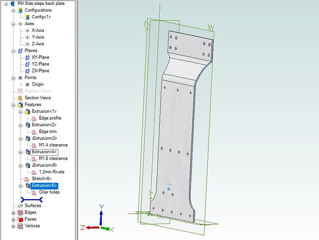 Back plate 3D by Roger Froud, on Flickr
... and this is how it looks after conversion. You can see that it keeps a handle to the original 3D part and redefines the bent part as proper sheet metal bends.
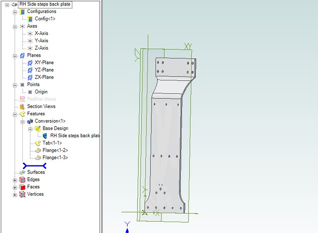 Back sheet metal by Roger Froud, on Flickr
Finally, I've added an Unbend operation which then shows it flat. The outline and holes can then be copied into a new part which has all the CAM operations for machining it.
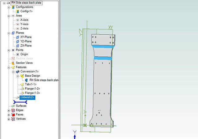 Back sheet metal flat by Roger Froud, on Flickr
I suspect more sophisticated packages fully integrate Sheet Metal with the 3D so this isn't an issue. For me, this is a real help. Trying to redefine a 3D model as a flat piece is possible but fiddly and easy to mess up. So now I have the best of both worlds. If the 3D model is altered, the Sheet Metal part follows suit when it's opened up again.
The back plate of the side steps on 1501 is a classic example. I know the extent of the joggle and how much it is. I'd drawn this on edge as a 3D model, but that's not convenient when you need to know what the profile would be like when it's unbent.
One solution is to draw it on edge, but then use the 'Convert to Sheet Metal' from the Part Modelling tab. What this does is to prompt you to say which part is considered the base and where the bends are. You can just click on those to select them.
This is how it looks when it's defined as a 3D model...
Back plate 3D by Roger Froud, on Flickr... and this is how it looks after conversion. You can see that it keeps a handle to the original 3D part and redefines the bent part as proper sheet metal bends.
Back sheet metal by Roger Froud, on FlickrFinally, I've added an Unbend operation which then shows it flat. The outline and holes can then be copied into a new part which has all the CAM operations for machining it.
Back sheet metal flat by Roger Froud, on FlickrI suspect more sophisticated packages fully integrate Sheet Metal with the 3D so this isn't an issue. For me, this is a real help. Trying to redefine a 3D model as a flat piece is possible but fiddly and easy to mess up. So now I have the best of both worlds. If the 3D model is altered, the Sheet Metal part follows suit when it's opened up again.


 .
.