mbrown
Elder Statesman

Posts: 1,720
|
Post by mbrown on Jan 7, 2019 21:45:12 GMT
If I go ahead with a German narrow gauge prototype as my next model, it will need a steam bell - the famous "Bimmel" which gave its name to "Bimmelbahn" for a small local railway. I sourced the attached diagram from the internet and am planning to see if I can make one which works - but the more I look at it, the more I doubt whether I have understood its operation. As I see it, the steam enters the lower chamber (photos show the bell is fed by a very small steam pipe) and pushes the valve upwards - this has to travel a fair way before opening to the upper chamber. As it rises, it pushes the rocker above the bell up and, I presume, as the valve opens, the steam escapes and the weight of the rocker closes the valve again, thus allowing the clapper to strike the bell. Fine in theory - but I can't work out why the steam pressure and the weight of the rocker don't just equalise with the valve part-open and the whole mechanism stationary. On the real locos, the clapper bounces up and down rapidly and clangs away merrily. But I don't quiet understand why it should do so. Any ideas, colleagues? I am minded to have a go at a model version just to test it in practice - but it would be good to have a better understanding of the theory first. Malcolm 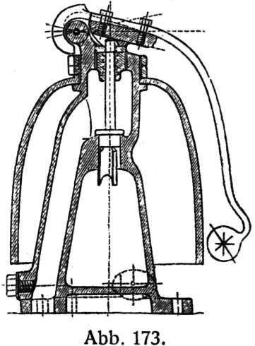 Steam bell Steam bell by malcolm brown, on Flickr |
|
jma1009
Elder Statesman
Posts: 5,901
|
Post by jma1009 on Jan 7, 2019 23:45:52 GMT
Hi Malcolm,
It seems pretty straightforward to me. The steam goes up the central section, raising the wing valve and in turn the clapper on a hinge which acts like a safety valve. Clapper hits side of bell. Clapper then returns to position in your pic. Think of an old fashioned weighted safety valve as opposed to a sprung valve, the clapper being the weight.
There may be a separate valve to the central section. Or a reducing valve. Pulling a bit of string or chain on the clapper would be just as effective rather than steam operated.
Having been involved in Church bellringing and tower restorations for very many years, I would imagine the 'bell' in your drawing would not give a very good 'sound'. More like a Swiss cow bell sound!
Cheers,
Julian
|
|
chrisb
Part of the e-furniture

Posts: 345
|
Post by chrisb on Jan 7, 2019 23:55:38 GMT
Carrying on from what Julian has said above, looking at the valve plug with its centralizing fins/wings below, it would appear that with the plug being a snug fit in its seat and the small steam flow will lift this like a piston until it exposes the wings which will give a big area to exhaust the steam in the central chamber, allowing the clapper and valve to fall back to the rest position.
Chris...
|
|
|
|
Post by suctionhose on Jan 8, 2019 0:36:20 GMT
Never seen one. As the clapper rises it arcs outward putting more load on the valve. I suppose if the steam supply flow was restricted / controlled you might get a pressure release when the wings opened allowing the clapper to drop.
Is it supposed to work continuously or ring once each time the operator pulls or pushes a valve?
|
|
mbrown
Elder Statesman
Posts: 1,720
|
Post by mbrown on Jan 8, 2019 7:32:23 GMT
Thanks Ross - from films, it appears that you turn it on and it then rings continuously. I think you may be onto something with the point about the changing angle of the clapper altering the moment and thus the down force....
Julian - Swiss cow bell is exactly the right sound! And ringing at quite a fast rate.
I guess the best way to find out is to make one....
Malcolm
|
|
|
|
Post by doubletop on Jan 8, 2019 8:29:43 GMT
As Malcom suggests if steam were applied to the inner chamber the steam pressure and mass of the clanger would reach a state of equilibrium. The diagram doesn’t have a steam inlet port on the inner chamber but it does seem to have a small hole at the cross wires lower right.
To get a system to oscillate at a sow rate there needs to be a charge a decay path, so how about these being vacuum operated by applying a vacuum to the outer chamber? There is a port at the bottom.
1) Stable state, no vacuum, inner chamber at atmospheric pressure.
2) Vaccum applied to outer camber it builds quickly
3) Mass of piston and clanger overcome and draws the piston upwards.
4) Outer chamber vacuum now in inner chamber and piston returns to closed position
5) Inner chamber slowly returns to atmospheric pressure through the small hole
6) Vacuum still aplied, loop to point 2 else point 1
Its probably not all there but you get the general idea. The 'ding' rate is determind by the sizes of the piston, the volume of the inner chamber and the size of the vent hole
Pete
|
|
Lisa
Statesman
Posts: 806 
|
Post by Lisa on Jan 8, 2019 9:25:19 GMT
If you go in the opposite direction to what Pete suggests, a small opening in the lower chamber would allow steam to gradually build pressure within, once the steam reaches sufficient pressure to lift the clanger arm it does so, which opens the valve and vents the steam to atmosphere, then the pressure drops, the clanger falls, and the process starts over.
As long as the steam enters the lower chamber at a slower rate than it can exit, then you'll get repeated ringing of the bell.
I'd guess the large passage on the left would be piped away elsewhere so that the exhaust venting doesn't affect the bell.
|
|
mbrown
Elder Statesman
Posts: 1,720
|
Post by mbrown on Jan 8, 2019 20:29:49 GMT
I think Lisa is on the right lines here - and her thoughts suggest to me that the proportions between the chambers, the valve and the weight of the clapper could be quite critical - as, perhaps is the ration between the steam entry and the exhaust. I have now done a bit more research on these bells - and have found diagrams of two variants. One, by Knorr, is quite complex and has no external clapper - the mechanism is like a small pop safety valve (compare comments above....) which "fires" a captive ball to strike the inside of the bell. Much too involved to make in a small scale, I suspect. But I also found this similar but different arrangement, although it doesn't accord with any picture is have seen of the actual fittings on locos. Frankly, this looks even less likely to work, but maybe the balance between the steam inlet and the sudden release as the valve opens (controlled by the lip on the flap) is the key. I also wonder whether the clapper itself is slightly springy and the rebound helps close the valve on both the designs. 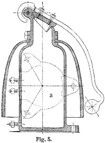 steam bell 2 steam bell 2 by malcolm brown, on Flickr I also found a discussion of steam bells on a German model railway forum (thank you Google Translate!). One member was querying the steam and exhaust connections and wondered whether a very small pipe was an oil pipe - only to be told that, no, there was no oil line to the bell (there was a picture of a driver - sorry, Lokfuhrer - oiling one manually) and stating that the steam supply was always through a very small pipe. That would accord with the idea that the in-flow of steam is quite gentle and the release as the valve opens is more violent thus triggering the clapper. In turn, this raises, I think, questions about condensation for a model version - but we'll cross that when we come to it.... So I think I will have a go at a small version of the first design - which apparently is by Latowski of Bremen - approaching the design of the valve as a kind of small pop valve and building a bit of spring into the clapper (bronze strip, perhaps). If it works - or even if it doesn't - I'll set up a thread! Thanks for all the ideas - keep them coming if there is more to learn. Malcolm |
|
|
|
Post by andyhigham on Jan 8, 2019 21:16:12 GMT
My sprint bike uses a similar principle to interrupt the ignition when gear changing.
When I press the button on my left handlebar air at 120psi enters a pneumatic cylinder attached to the gear linkage, it also enters a small cylinder with a floating piston, the floating piston moves along the cylinder against a light spring and operates a microswitch which kills the ignition. There is a small hole about 0.7mm diameter drilled axially through the floating piston, air leaks through this hole equalising the pressure on both sides of the piston allowing the piston to return, releasing the microswitch and re energising the ignition. The time the ignition is off can be adjusted by varying the hole size.
|
|
mbrown
Elder Statesman
Posts: 1,720
|
Post by mbrown on Jan 8, 2019 21:30:41 GMT
Thanks Andy,
I was wondering whether a light spring to return the valve to the closed piston might be useful - given the smaller masses involved in a model version.
I feel some experimenting coming on - but it will have to wait at least until the weekend!
Malcolm
|
|
|
|
Post by suctionhose on Jan 8, 2019 22:35:39 GMT
I was going to mention the mass issue. At 1/10 scale you 1/1000 the mass, 1/100 the piston area and perhaps the same pressure as full size! Proportions are quite distorted!
Reckon something more positive like a double acting shuttle valve might be needed!
Good luck!
|
|
|
|
Post by ettingtonliam on Jan 9, 2019 2:26:30 GMT
I think Lisa is on the right lines here - and her thoughts suggest to me that the proportions between the chambers, the valve and the weight of the clapper could be quite critical - as, perhaps is the ration between the steam entry and the exhaust. I have now done a bit more research on these bells - and have found diagrams of two variants. One, by Knorr, is quite complex and has no external clapper - the mechanism is like a small pop safety valve (compare comments above....) which "fires" a captive ball to strike the inside of the bell. Much too involved to make in a small scale, I suspect. But I also found this similar but different arrangement, although it doesn't accord with any picture is have seen of the actual fittings on locos. Frankly, this looks even less likely to work, but maybe the balance between the steam inlet and the sudden release as the valve opens (controlled by the lip on the flap) is the key. I also wonder whether the clapper itself is slightly springy and the rebound helps close the valve on both the designs. steam bell 2 by malcolm brown, on Flickr Malcolm I'm inclined to think you are right about the springiness of the clapper arm. I think the valve opens, shoots the clapper arm upwards till it hits the stop, then the arm rebounds, slams the valve shut and hits the lower stop, just before the clapper hits the bell. The springiness of the arm lets the clapper travel a little further till it hits the bell and rebounds. I know from working on clocks that the hammer in its rest position has to be clear of the bell, otherwise the note is a dreadful flat thud, not a nice clear ring. Early steam railways such as Stockton and Darlington used a much simpler method to achieve the same result. They had a bell hanging from a pivot shaft with an arm, to which was tied a piece of cord, the other end of the cord being tied to a convenient pice of the valve machanism, so that when the loco travelled along, the cord kept tugging on the bell arm, causing it to ring. Must have been dreadful driving a loco with a continuously ringing bell. Like the old rhyme about Noddy - 'On my hat theres a jingling bell, the ringing in my ears is absolute h--l' On that note, good night. |
|
|
|
Post by yorkshireman on Jan 9, 2019 15:11:35 GMT
Hallo together
The sound of a Bell is not scalable. Please do not expect a sound that is any different from the Jinglebells at XMass...
I do have however some drawings of a working Steam operated Loco Bell for 5" Locos.
Unfortunately I do not remember where these drawings came from and I cannot tell whether the sound is anywhere realistic.
I am ready to email copies on a private basis to the first 3 members that ask me nicely for it.
Kind Regards
Johannes
|
|
mbrown
Elder Statesman
Posts: 1,720
|
Post by mbrown on Jan 9, 2019 19:28:57 GMT
Thank you very much for this kind offer Johannes - I have sent you a p.m.
Cheers
Malcolm
|
|
mbrown
Elder Statesman
Posts: 1,720
|
Post by mbrown on Feb 2, 2019 22:39:50 GMT
I decided the only way to find out how the steam bell works was to make one.... Johannes (Yorkshireman) very kindly sent me drawings for a 5"g model bell. This confirmed my view that the action resembled a pop safety valve, and it also showed how to overcome a problem that had puzzled me - how to clear condensate from the steam chamber. The drawing of the prototype showed no provision for this, but the model drawing had the exhaust leading down into a small sump beneath the steam chamber to which it was connected by a 0.2mm hole - small enough make little difference to the pressure in the inlet chamber, but allowing condensate to drip through to exhaust. On the other hand, the model design was based solely on turned parts fitted together with O rings and it was a bit bigger than scale for my needs. As this was pure experimentation, I decided I could make something closer to the prototype using stock I had lying around the workshop. So I started with the bell itself.... The prototype bell was a casting and the model drawings showed one turned from solid. I had no suitable material for that so tried spinning it from 18g gilding metal over a turned former. 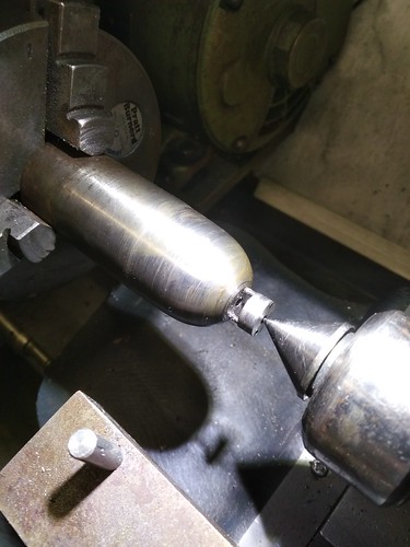 IMG_20190113_1608252 IMG_20190113_1608252 by malcolm brown, on Flickr My previous attempts at spinning have been on components which allowed for decent sized driving dogs through parts of the sheet that would later be cut away. Here, I had only a 1/4" hole in the top of the bell, so I arranged two 3/64" pegs to drive the metal. Unfortunately after 4 or 5 annealings, the forces involved started to tear the pegs through the metal long before I had got it spun down to the former.  IMG_20190113_1631574 IMG_20190113_1631574 by malcolm brown, on Flickr So time for Plan B.... I decided to make it by the raising method which Geoff Nicholson used to demonstrate at Midlands exhibitions in the days when they were held at Birmingham University. I used this method for the dome on my Burma Mines loco. You start with the annealed disc and the egg shaped hammer on a sand bag, using the rawhide hammer occasionally to stop creases developing. After 4 or 5 annealings, I had a dish like this. 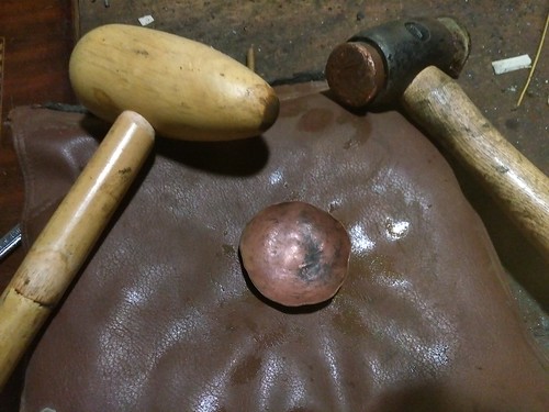 IMG_20190113_1708079 IMG_20190113_1708079 by malcolm brown, on Flickr Then using the former as a stake, the raising hammer is used to draw the edge down little by little. After another half dozen annealings, I had something like a sombrero....  IMG_20190113_1720237 IMG_20190113_1720237 by malcolm brown, on Flickr After that, I lost count of annealings, but eventually I had something approximately correct. At this stage, I should have started using the planishing hammer to smooth out the surface, but by this stage the metal at the top of the bell was paper-thin and I was afraid of splitting it. As it was only for an experiment, I left it as it was, especially as it made a nice ring when hit by a small spanner!  IMG_20190113_1918045 IMG_20190113_1918045 by malcolm brown, on Flickr I didn't take photos of the other components until they were finished, but here they are all laid out. The main body is in the middle with a 3/16" copper pipe leading the exhaust down to a flange at the base. The steam inlet through a 1mm choke is at the side. The valve seat to the right screws in about half way up, and the valve is seen above it, with its 1/16" extension rod to work the clapper. Below is the base and above that a small plug which separates the sump (connected to the exhaust flange) from the steam chamber, although you can't really see the 0.2mm drain hole in the middle of it. A nipple at the top screws into the body and acts as a guide for the valve rod and allows the bell to be secured by the brass nut. The clapper mechanism screws over that with the valve rod striking it about 7/32" from the pivot.  IMG_20190202_1651343 IMG_20190202_1651343 by malcolm brown, on Flickr And this is the finished article, although I didn't get the light right. You can see the 1/16" steam inlet pipe connected up.  IMG_20190202_1655498 IMG_20190202_1655498 by malcolm brown, on Flickr So... does it work?? The answer at the moment is - sort of..... On air, and with the clapper removed, I can get the valve to pop in and out very rapidly - but only at one, very critical, pressure. Unfortunately, this pressure is not enough to lift the clapper. With more air pressure, the clapper pops up smartly, but then stays up until the air pressure in the line is dropped. Maybe it will work better on steam - after all, injectors don't work on air and pop valve behave differently on air to steam.... I shall have to steam up a loco and arrange a connection to the manifold somehow.... But I suspect that, with a bit of fiddling and maybe changing the dimensions of the valve, it might be made to work. I won't have any workshop time for a few weeks, but watch this space - eventually! Malcolm |
|
|
|
Post by yorkshireman on Feb 3, 2019 5:34:02 GMT
Very nice, Malcom.
I do admire your persistence, surely you will get it working.
Johannes
|
|
steam4ian
Elder Statesman
One good turn deserves another
Posts: 2,069
|
Post by steam4ian on Feb 4, 2019 2:23:15 GMT
Malcolm. Admirable work.
I suggest that you don't clamp the bell tight on the spindle, if you do you risk damping the ring and only getting a thud/click.
One of the prototype designs indicates a bit of float.
Ian
|
|
mbrown
Elder Statesman
Posts: 1,720
|
Post by mbrown on Feb 4, 2019 7:31:23 GMT
Thanks Ian,
Yes, I had worked out that this was the probable reason for the prototype having two nuts above the bell - i.e. as lock nuts so that the bell was not clamped down hard.
My top nut carries the clapper pivot and there is another nut beneath it so I can adjust the "fit" of the bell.
In practice, I found that it only takes a very little slackness between the bell and the main body for it to give a reasonable ring - of course, in this size, it's a tiny "ting" rather than a loud "bong" but it's the operating mechanism that I am interested in at this stage.
Best wishes
Malcolm
|
|
|
|
Post by chris vine on Feb 5, 2019 9:51:54 GMT
Hi Malcolm,
I think you will have to play with the relative sizes of the steam supply pipe (needle valve) and the exit passage when the clapper lifts.
You are trying to get a slow build up of pressure, until it overcomes gravity. Then the lift and quick release. The supply isn't sufficient to keep it lifted.
I think that the leakage past the operating seal/piston will be important. If it is leaking a lot, then you will need a big supply of steam to raise the pressure to lift it and then it may tend to stay lifted.
Chris.
|
|
mbrown
Elder Statesman
Posts: 1,720
|
Post by mbrown on Feb 5, 2019 15:16:14 GMT
Thanks Chris,
The more I look at it, the more critical variables there seem to be - diameter of the valve; length of the valve; size of steam inlet; size of exhaust outlet - and, perhaps most of all, the steam pressure. The last of those will, of course, fluctuate to some extent - the real thing would have had to function even when the loco was steaming poorly, so there must be some leeway in practice.
I suspect this is going to take a lot of trial and error - but until I either locate better drawings of the loco I am interested in, or get over to Germany to measure it up, I haven't much else to do for a while!
Best wishrs
Malcolm
|
|


