|
|
Post by simplyloco on Aug 17, 2019 19:30:40 GMT
Ashpan And Grate CompletedI have spent today devising an arrangement where I can drop the grate easily, and put it back again reliably and accurately! I also wanted sufficient room alongside the grate to run a few important copper pipes...  I'm pleased with it, and thanks again for the advice. John Here is the completed gadget. It is an experiment only, the ashpan being made of thin galvo, but if it works I'll make a deeper stainless one. The slots engage with the very convenient fixed spring hanger bolt heads, and there is a stainless tube swaged into the firebox inner flange which takes the retaining pin. The other hole is in the wrong place...   20190817_185100 20190817_185100 by inkaboat, on Flickr Firebox incorporating the alignment tube.  DSC00184 DSC00184 by inkaboat, on Flickr Locating point.  20190817_185413 20190817_185413 by inkaboat, on Flickr Ashpan in place.  DSC00190 DSC00190 by inkaboat, on Flickr Another pic!  DSC00186 DSC00186 by inkaboat, on Flickr My steamoitus Interruptus tool. Confucus, he say, " Better to have Old Hen than Pullet!"  DSC00194 DSC00194 by inkaboat, on Flickr These little 'knock in' rivets are dead handy for quick constructions into solid metal, as in the stretcher at the front of the ashpan. 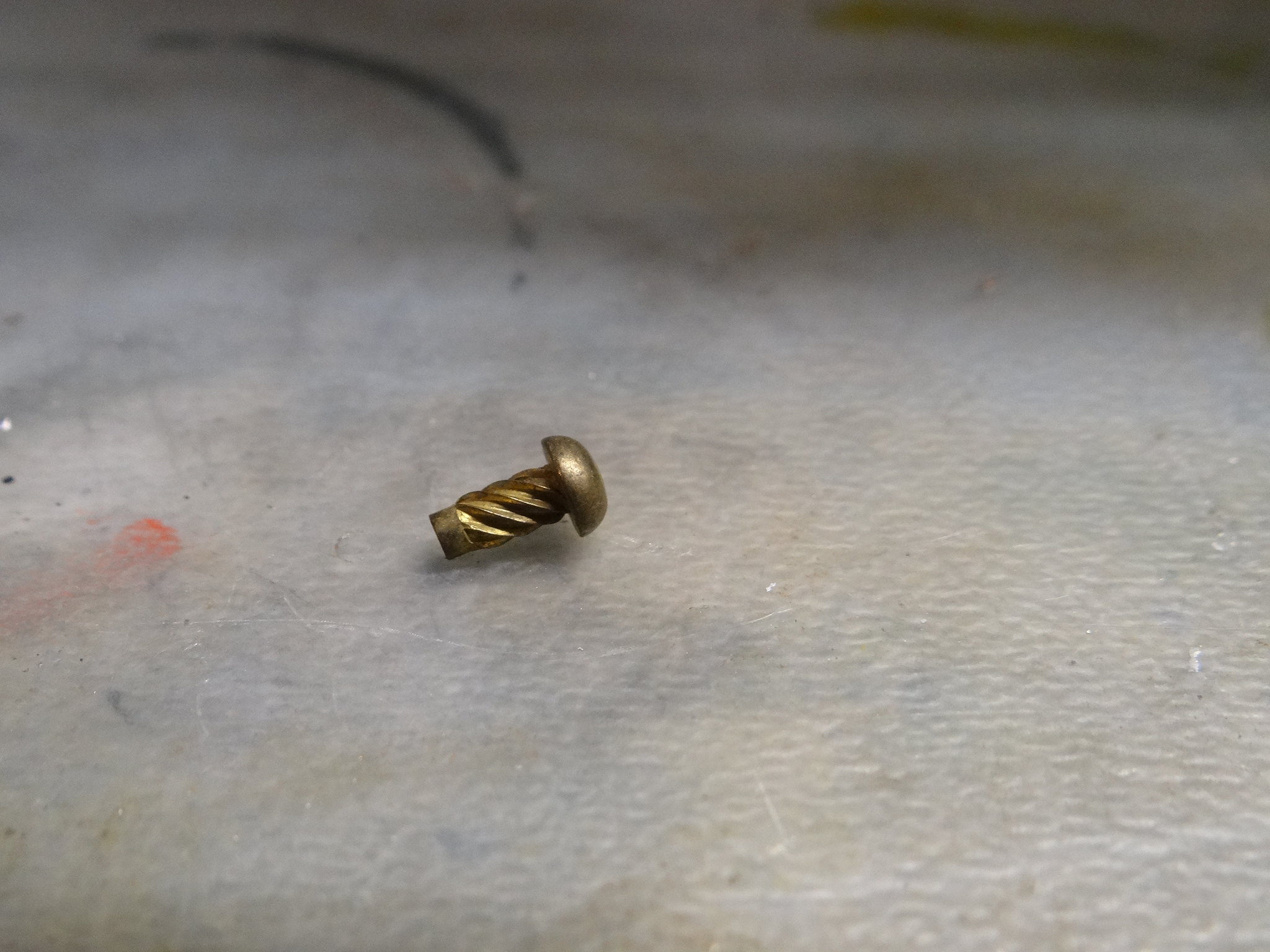 DSC00192 DSC00192 by inkaboat, on Flickr
|
|
|
|
Post by silverfox on Aug 17, 2019 20:31:50 GMT
They look interesting. Who supplies them?
|
|
jma1009
Elder Statesman

Posts: 5,901
|
Post by jma1009 on Aug 17, 2019 20:43:17 GMT
Hi John,
If it were me, I would open up the front of the ashpan bending it forwards a bit, and cut a slot in the bottom of the front, to allow the ash to fall out and a bit of front air, given also that the ashpan slopes down towards the front.
I would attach a piece of stainless to the frame stretcher in front of the throatplate, extending someway downwards from this frame stretcher, to prevent ash getting on the eccentrics etc when lowering your hinged grate when dropping the fire.
Cheers,
Julian
|
|
|
|
Post by simplyloco on Aug 17, 2019 20:57:00 GMT
Hi John, SNIP I would attach a piece of stainless to the frame stretcher in front of the throatplate, extending someway downwards from this frame stretcher, to prevent ash getting on the eccentrics etc when lowering your hinged grate when dropping the fire. Cheers, Julian Julian I like your idea to minimise contamination, and I will use it, for which I thank you. The ventilation arrangements,alas, are as per original design, and will remain as they are. John |
|
|
|
Post by simplyloco on Aug 17, 2019 21:00:32 GMT
They look interesting. Who supplies them? The source is lost in the mists of time... Someone will know! You can take a few as swag when you visit! John |
|
|
|
Post by ettingtonliam on Aug 17, 2019 22:47:44 GMT
When you make the 'proper',deeper ashpan is there any advantage in making it deeper at the back so the bottom slopes backwards, not forwards?
|
|
|
|
Post by simplyloco on Aug 17, 2019 23:17:03 GMT
When you make the 'proper',deeper ashpan is there any advantage in making it deeper at the back so the bottom slopes backwards, not forwards? I wouldn't have thought so, but I can't see the reasoning behind your question. When I mentioned a deeper one I was only talking about a few mm to increase the free space below the grate. The current one has 20mm free space below, which some might say is a bit tight. Sloping forwards prevents the contents exiting backwards to ignite the surrounding countryside! John |
|
|
|
Post by ettingtonliam on Aug 18, 2019 6:47:07 GMT
I just thought that having the bottom sloping to the front, when running the ash might shake towards the front and after a while begin to choke the grate. Sloping backwards it wouldn't. I take your point about setting fire to the surroundings.
|
|
stevep
Elder Statesman
Posts: 1,070
|
Post by stevep on Aug 18, 2019 7:53:57 GMT
I think you need to do something at the back too, else all the ash will go over the rear axleboxes. They always seem to be the ones to wear first.
|
|
|
|
Post by gwr14xx on Aug 18, 2019 9:11:36 GMT
They look interesting. Who supplies them? Try Googling 'Drive Screws'
Eddie.
|
|
|
|
Post by silverfox on Aug 18, 2019 9:23:13 GMT
Gents
Thanks for all the replies
It was one of those 'i will buy that ,and then see where i can use it' question, asi have done with many bits over the years A few sheets of brass sheet 4x2 ( and thats feet!) with bits cut out here and there! are all around the shed
Ron
|
|
|
|
Post by glynmar on Aug 18, 2019 16:46:24 GMT
So I have cleaned and stripped a lot of the old paintwork on the Stirling and it looks a lot more presentable. Being a novice some bits are baffling me. I know the engine was dismantled originally because of a leaking regulator before I purchased it, however I am trying to take the regulator apart without much success. I have included a link to Flicker with pictures. The regulator rod came out OK but it is not true. The Flange at the backhead end snapped off in trying to remove it so I will need to get the centre bit out somehow plus a broken bolt. At the front end I can remove the tube out only 16" as there seems to be a flange on the end stopping it being removed completely, the boiler length is 19". This tube is not drilled anywhere along it's length. The flange on the front seems to be soldered to the boiler so I can't figure out how you can remove this allowing removal of the tube. I haven't seen a drawing for this type of regulator and when I received the engine the front end was blanked off for testing and no parts for connecting the steam to the cylinders was supplied. The cladding is also a bit of a mystery in that the boiler came with cladding fitted which when you fit the cab over it there is 1/2" gap between the bottom of the cab and the running board. A short addition piece of cladding was supplied that show marks where the safety valve cover was fitted but there are no marks on the cladding that is now fitted. If I cut the cladding so the cab sits on the boiler rather than on top of the cladding I guess this might solve the problem. I do wonder if I have bought an engine that has parts from another Stirling hence the miss match of parts. flic.kr/s/aHsmGg61p9 I have only just joined Flicker to upload the Photos so I hope it works. Any help would be appreciated Glyn |
|
|
|
Post by simplyloco on Aug 18, 2019 17:49:45 GMT
So I have cleaned and stripped a lot of the old paintwork on the Stirling and it looks a lot more presentable. Being a novice some bits are baffling me. SNIP Any help would be appreciated Glyn Glyn. I'm on the same learning curve as yourself regarding the Stirling Singles! The (unfinished) regulator tube on mine had two concentric collars inside, held in radially by csk 10BA screws. If yours is the same those screw heads might be impeding the withdrawal of the tube, which has to come out one way or another. It looks like you will be fitting another regulator so you could be a bit rough with it! Do you have the relevant drawings? I can't help on the cladding as I haven't got there yet...  I have no wish to discourage you from posting, but have you considered starting your own build/restoration thread? People on here are quite helpful! John |
|
|
|
Post by delaplume on Aug 18, 2019 21:12:07 GMT
Gents Thanks for all the replies It was one of those 'i will buy that ,and then see where i can use it' question, asi have done with many bits over the years A few sheets of brass sheet 4x2 ( and thats feet!) with bits cut out here and there! are all around the shed Ron Hi Ron------- my first thought was the MoD as almost every bit of their engineering items seems to have a small, Aloominum Modification Plate attached by these screws....... 10 years have now passed since my retirement and I need to stock up again so thanks also for that link.........I'll go and get some straight away and replace my Chester Lathe main nameplate !!!!! Alan |
|
|
|
Post by simplyloco on Aug 18, 2019 21:35:52 GMT
12 Oz. Vertical InjectorDavid kindly gave me this D.A.G Brown injector to use on the Stirling. Having had a look at the DAG 'Bible', he says that just about every 5" loco on the planet should get away with a No. 2 injector, so to paraphrase Caesar: I came, I saw, I concurred...  I had a few goes at wiggly bits of under and over pipe, and then I discovered this simple path behind the splasher. The return from the injector will go up by the LH side of the brass keeper and travel just a few cm to the clack. The water inlet will go straight back to the transom - sorry! - drag beam...  20190818_220005 20190818_220005 by inkaboat, on Flickr The piping from the turret blends nicely into the curve of the backhead.  20190818_215651[1] 20190818_215651[1] by inkaboat, on Flickr I don't think that I will do any better than this, and it doesn't interfere with the drop grate. Well happy! John  20190818_220213 20190818_220213 by inkaboat, on Flickr
|
|
|
|
Post by glynmar on Aug 18, 2019 22:44:54 GMT
Hi John, Thanks for your reply regarding my Stirling. Regarding drawings I am going to get the Reeves later set. As apparently they are the most detailed however I think mine is done to the original Scarth design according to the steam test certificate built by K Cirket and completed in 1989. As you say it would be better not to piggyback your thread so I will set my own up for my project and look forward to reading about your progress in your thread. This is very much a voyage of discovery for me. Challenging but at the same time fascinating. Glyn
|
|
|
|
Post by jon38r80 on Aug 19, 2019 10:49:18 GMT
Those "drive screws" were used on a lot of machines in the past to hold on name plates and scales. I bought some off EBay when I wanted to fix a bit of stainless ruler to my offset centre for the lathe tailstock. Very handy and neat and can be prised out with a thin screwdriver blade. The seller was down in the west country somewhere. Stuff like that just doesn't appear in Oxfordshire.
|
|
|
|
Post by ettingtonliam on Aug 19, 2019 12:34:49 GMT
Sorry if this is unacceptably offtopic, but my WW2 vintage Colchester Master had its cast brass plates held on by brass round head screws which had been simply hammered into a tapping sized hole in the main casting. Nothing fancy, and easy to drill out if they couldn't be prized out.
|
|
|
|
Post by simplyloco on Aug 19, 2019 13:03:43 GMT
Injector Installation CompletedIf I said that this was a very easy job then you would ALL know that I was lying through my teeth! A bit neater than many I have seen though... John  DSC00200 DSC00200 by inkaboat, on Flickr You can start calling me 'Harpic' soon, as I'm going clean round the bend!  DSC00196 DSC00196 by inkaboat, on Flickr Economic plumbing!  DSC00195 DSC00195 by inkaboat, on Flickr I just had to cut a little dart in the corner of the grate to clear the water feed pipe and it goes in easily.  DSC00197 DSC00197 by inkaboat, on Flickr The job was made much easier when I remembered I had the plumbers' solder!  20190819_093011 20190819_093011 by inkaboat, on Flickr
|
|
|
|
Post by simplyloco on Aug 19, 2019 18:51:43 GMT
Backhead CompletedHaving made such good progress today I revved up and sorted the backhead fittings. Forgive me for saying so, and I know that there is no brake valve, but this is one uncluttered backhead! The whistle pipe goes round the back of the glass and down the LHS, ready to be connected to a whistle, mounted somewhere in the bowels of the beast! I'm going to have to make a smaller injector valve hex nut, but the thread is 9/32" so 5/16" hex is pushing my luck a bit!  DSC00215 DSC00215 by inkaboat, on Flickr
|
|


