|
|
Post by Roger on Aug 7, 2019 21:48:47 GMT
Apologies if the photos are the wrong size, I'm using a Photobucket account for these to keep them separate from my other uploads. I thought I'd share some shots of the CNC conversion while I strip it for maintenance. The Z-axis has been a bit suspect for a while, with the odd clunk when it does the first move of the day. I'm also not happy with the backlash compensation with it as it is. The strip down is intended to check the leadscrew that operates the knee and to see if there's a problem with the slideway. It's had a pretty hard time so I expect it's pretty worn and needs some adjustment. What it really needs is shipping off to someone to regrind the ways, but I can't afford to be without it for a long period so that will have to wait until another time. Anyway, here are a few shots to show some of the conversion details. This is a top quality ground recirculating ball leadscrew which I had from the machines I still support. Alternate bolts go through the bellows retainer. I wish I had beefed up the casting, it's a bit thin where the nut is. 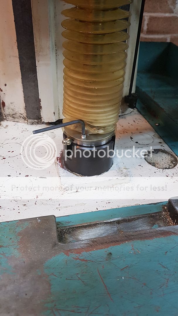
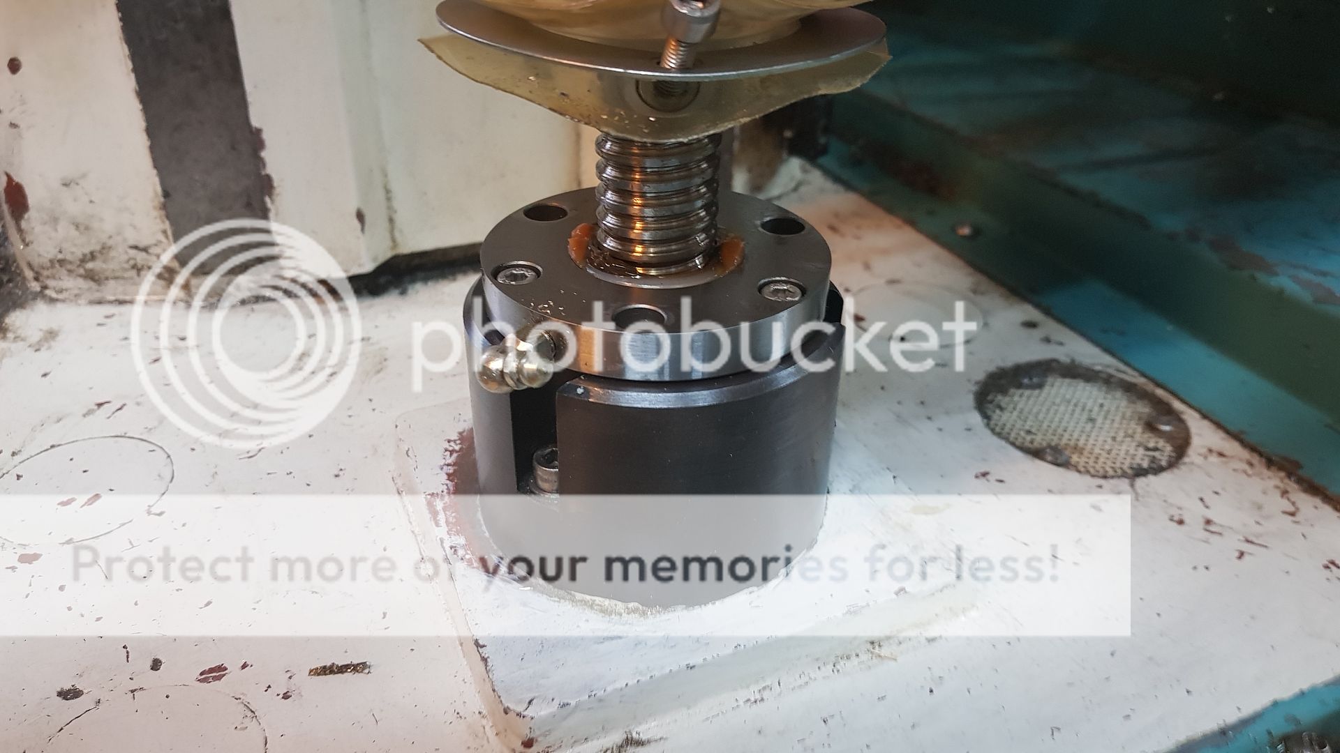 You can see the little tubes that return the ball bearings from one end of the bearing to the other. 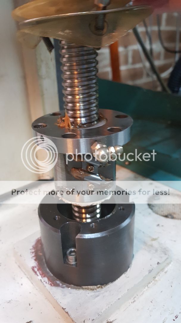 At the moment I don't use the Linear scales. They were very expensive Newall types which I hope to use at a later stage. At the moment, the options for doing that are limited and I think I'm going to have to do my own thing with the electronics for that. Some sort of Fuzzy Logic seems favourite, but I need more time to sit down and work out a solution. 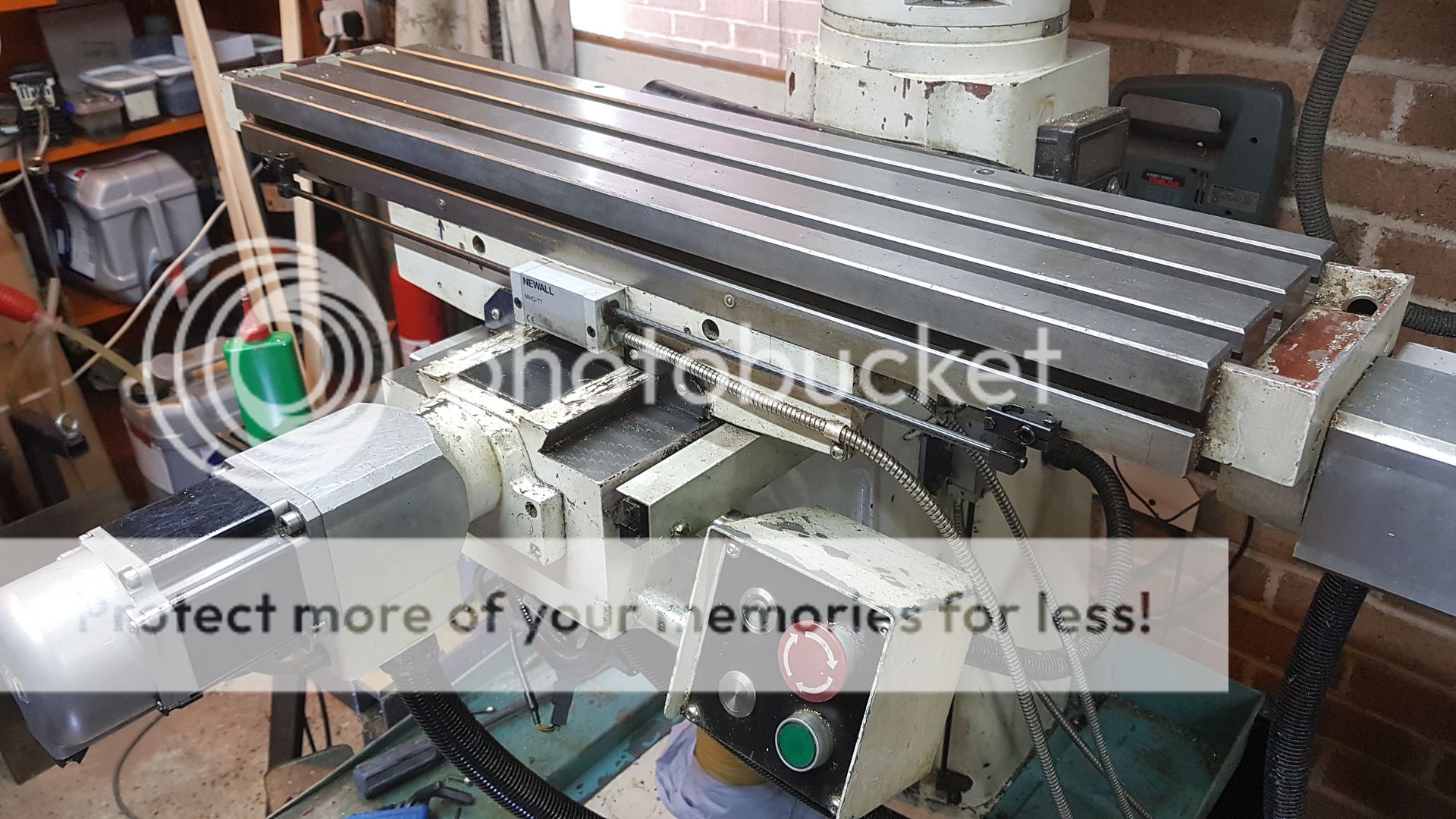 The AC Servos has a plain shaft but the THK leadscrews have a keyway. 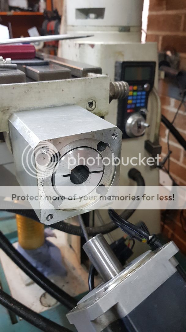 I made the flexible couplings from aluminium. 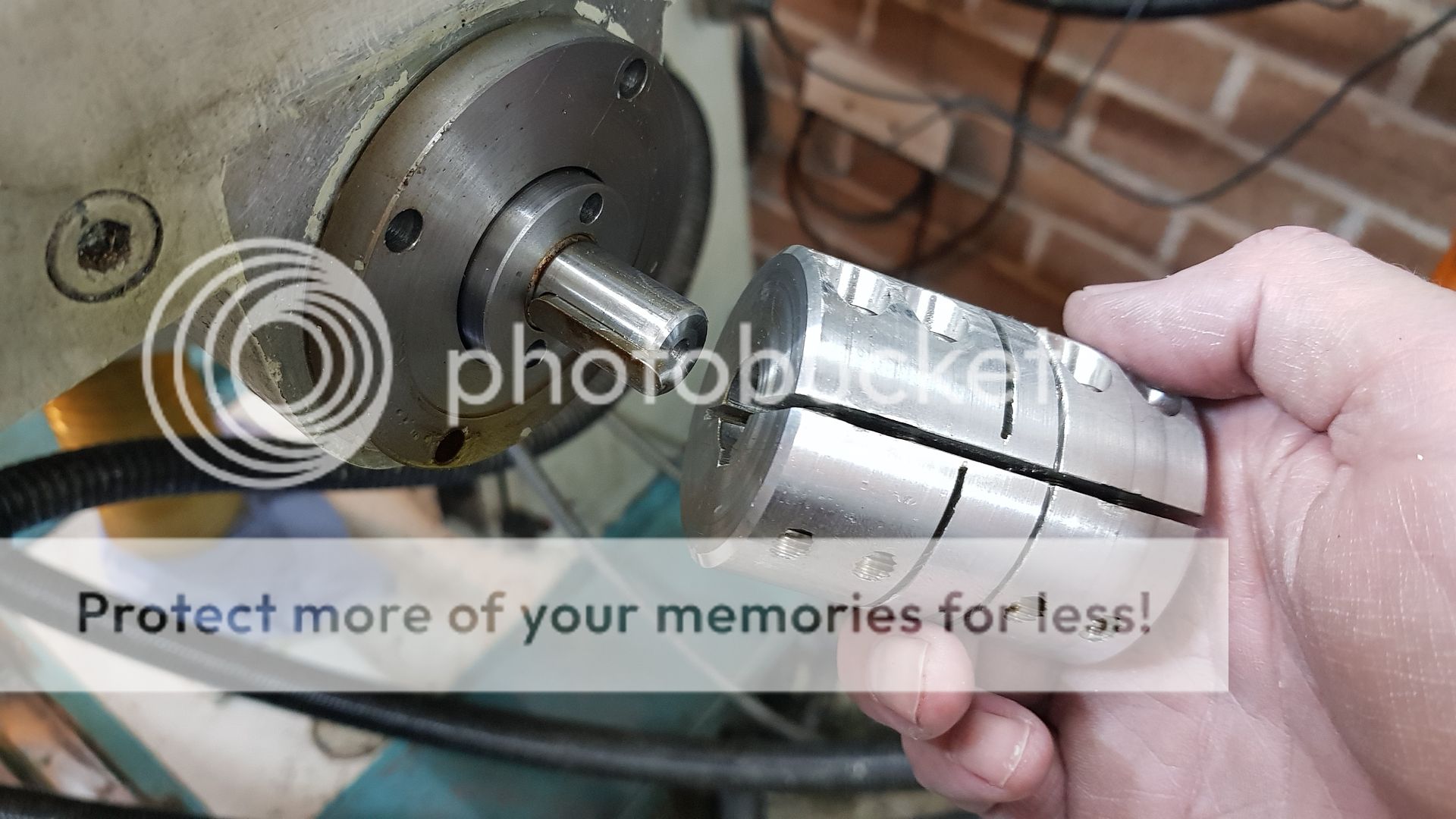 The undriven end of the X-axis servo is supported by a bearing with an oil seal. 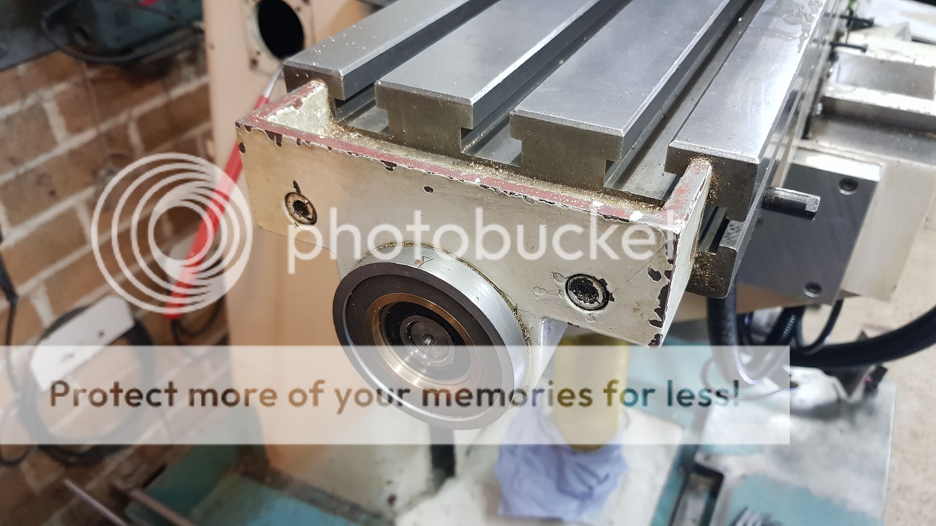 That just pulls off. the big sleeve is a mechanical end stop made from Grey PVC 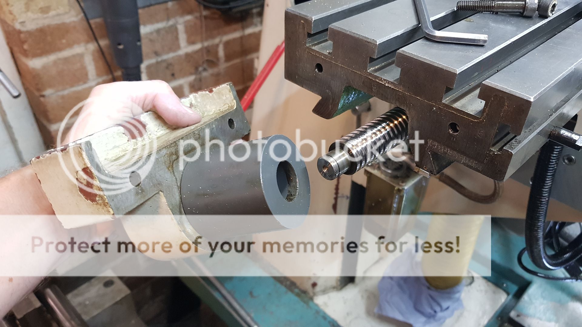 I can't find the spanner to undo the nut on the end of the thrust bearings at the moment, but I can get the table off without it. The large flange on the RH side of the thrust housing doesn't touch the cream coloured housing. Instead it bears on the outside of the thrust bearing pair. There are two angular contact bearings back to back which are supplied ground to give the correct preload if you clamp the outer races and inner races solidly in the housing and on the shaft. There's no adjustment. 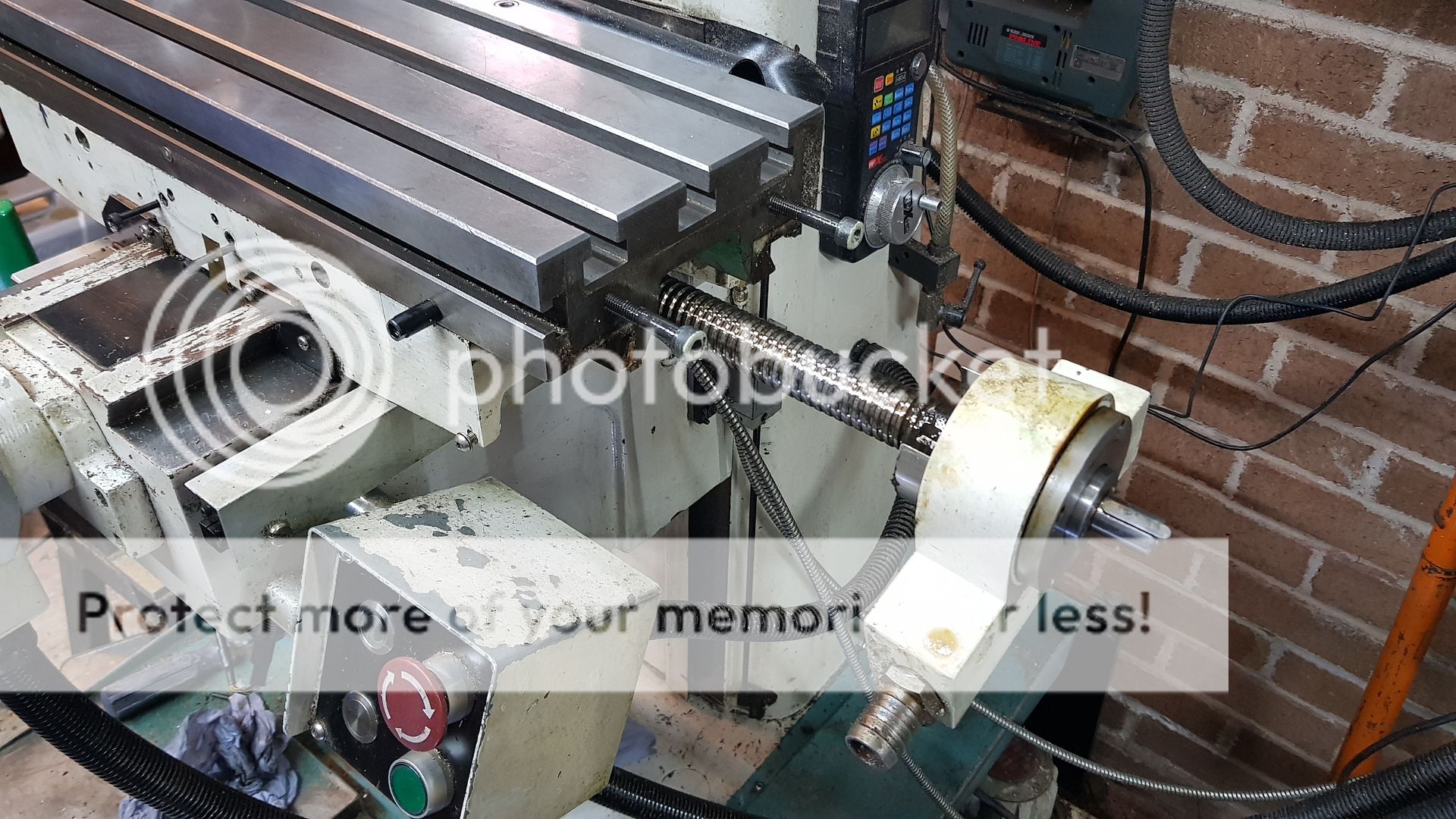 You can see how little room there is under the X-axis. I had to search really hard to find a leadscrew with a small enough ballnut, most of them are round. 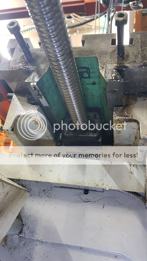 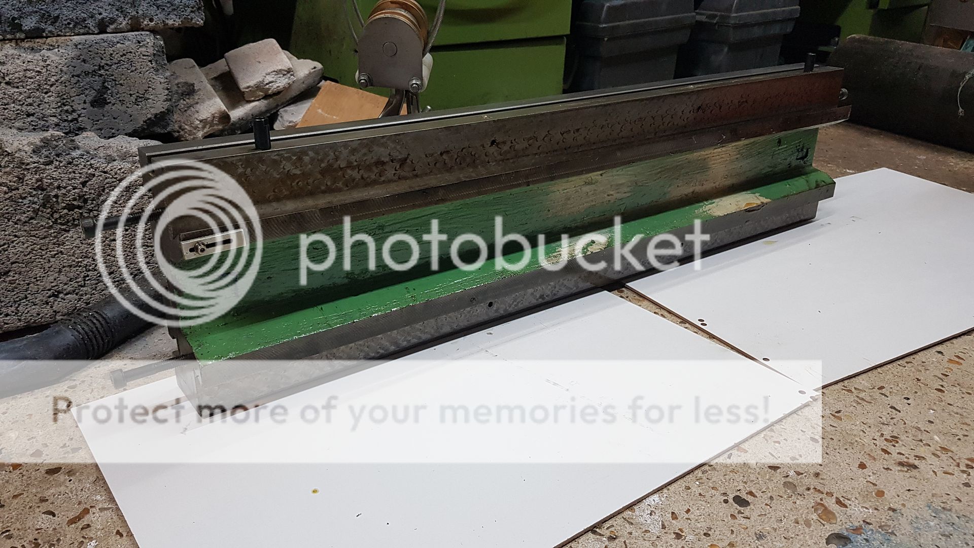 The Y-axis leadscrew thrust arrangement is the same. 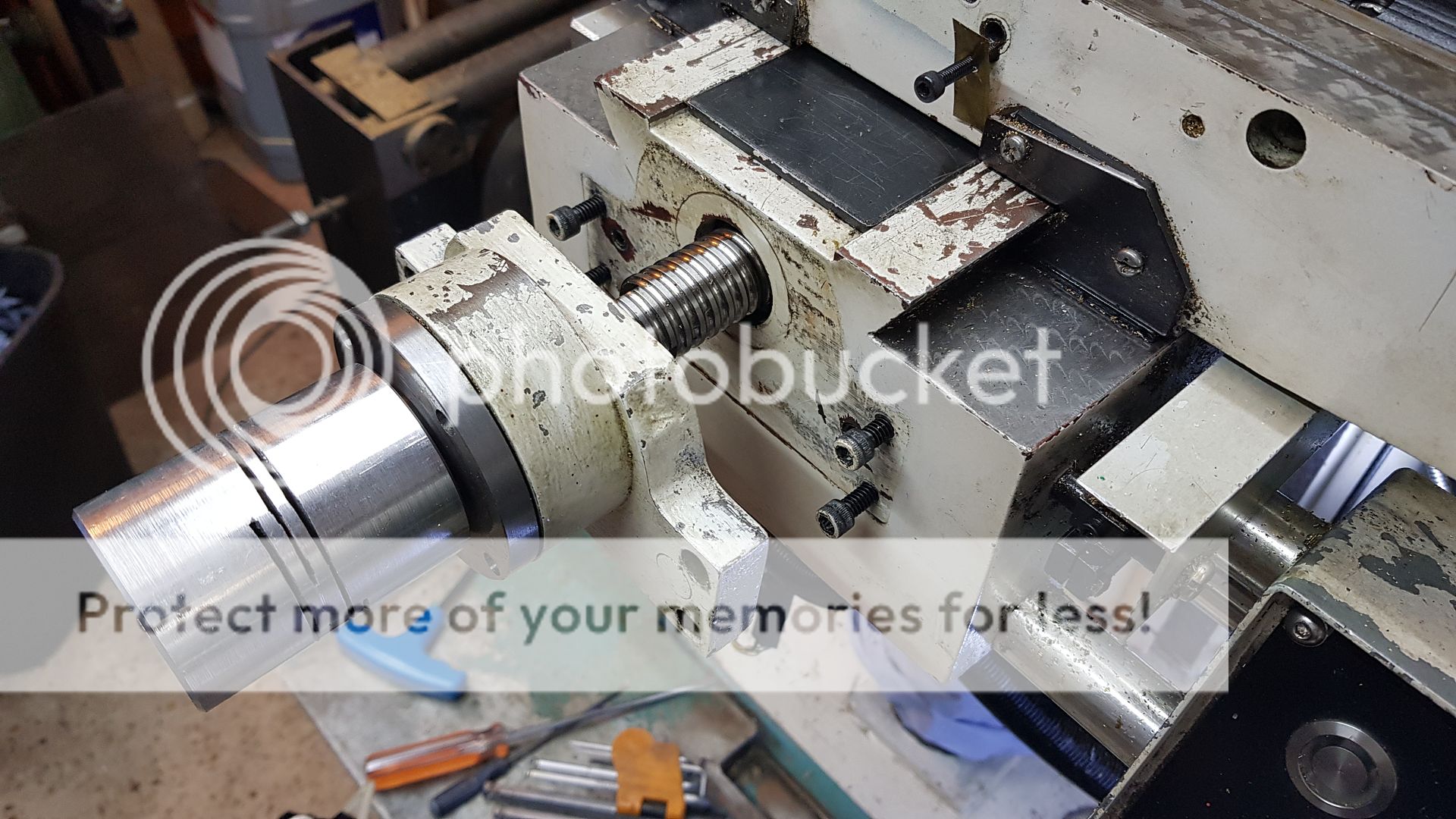 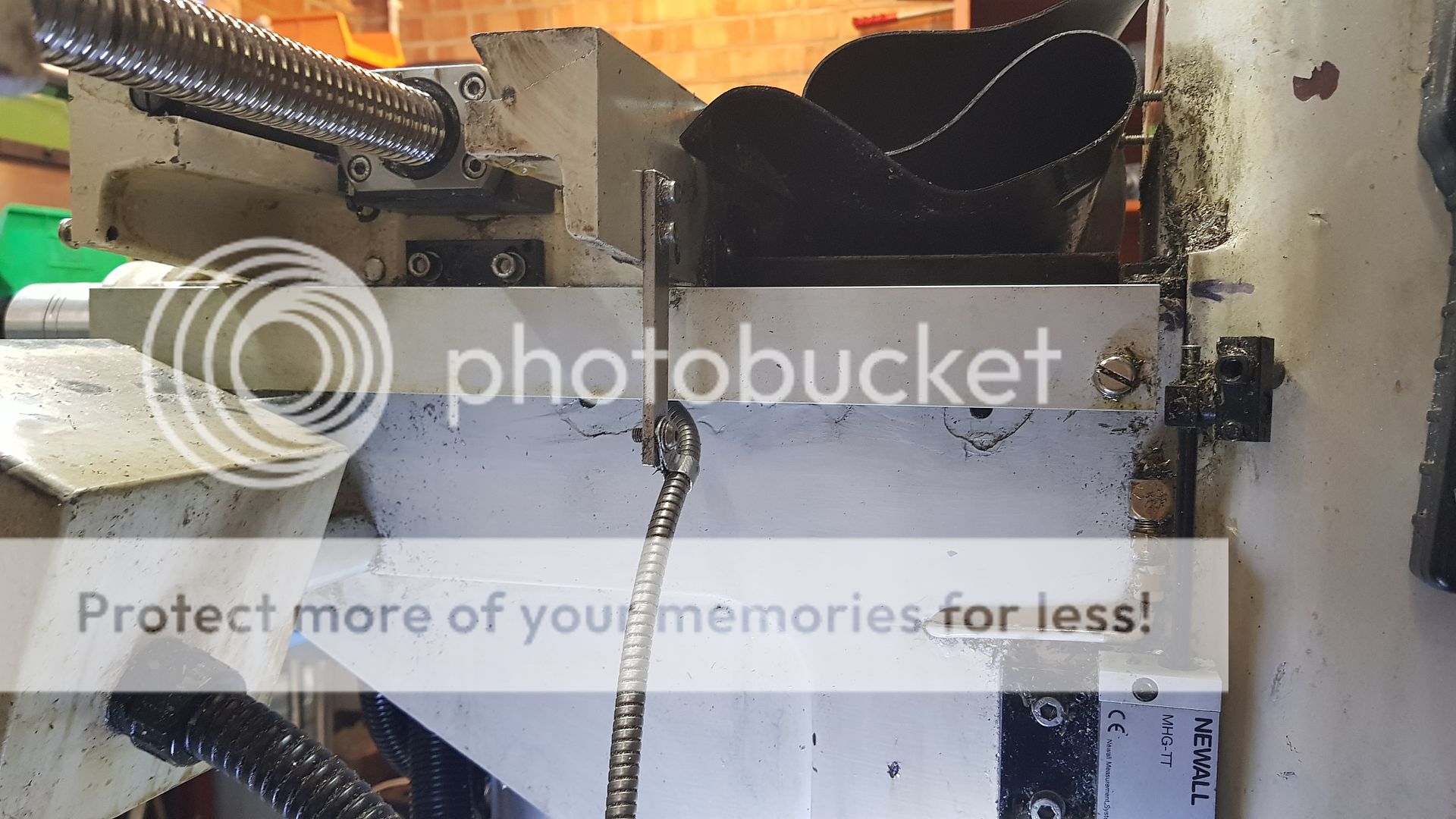 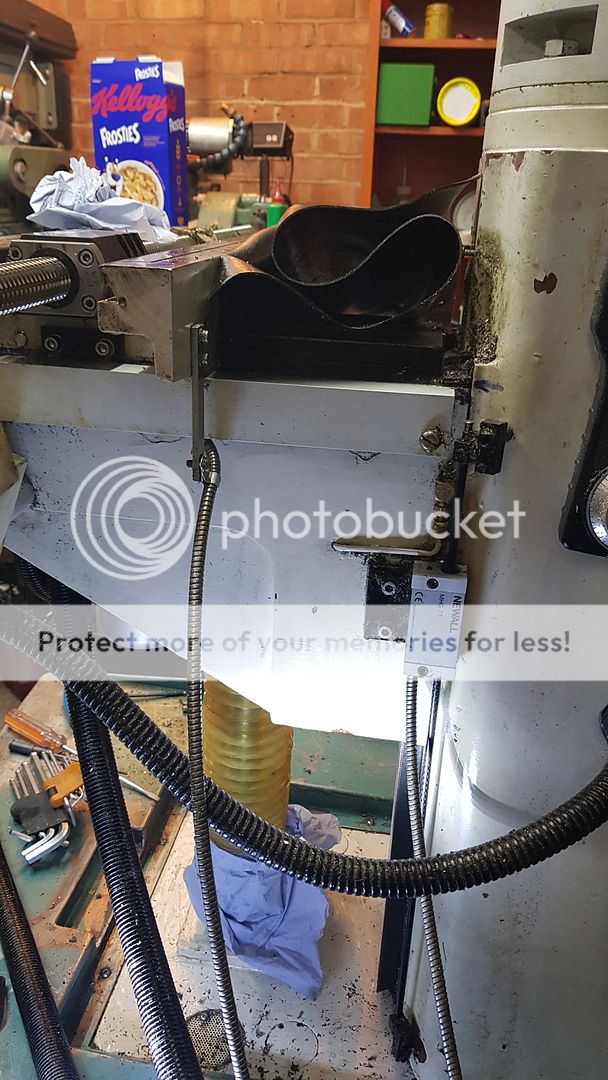 Finally you can start to see the Z-axis drive arrangement. This was the biggest challenge of the conversion due to the limited space. I still need to get the Y-axis leadscrew out of the way so I can get to it. 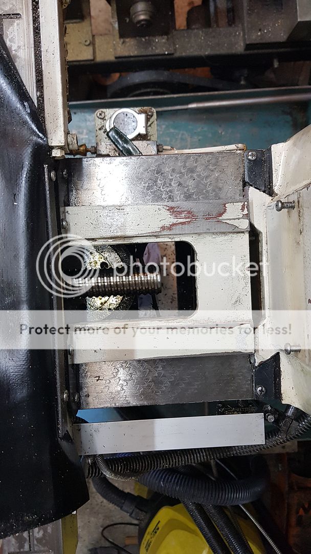 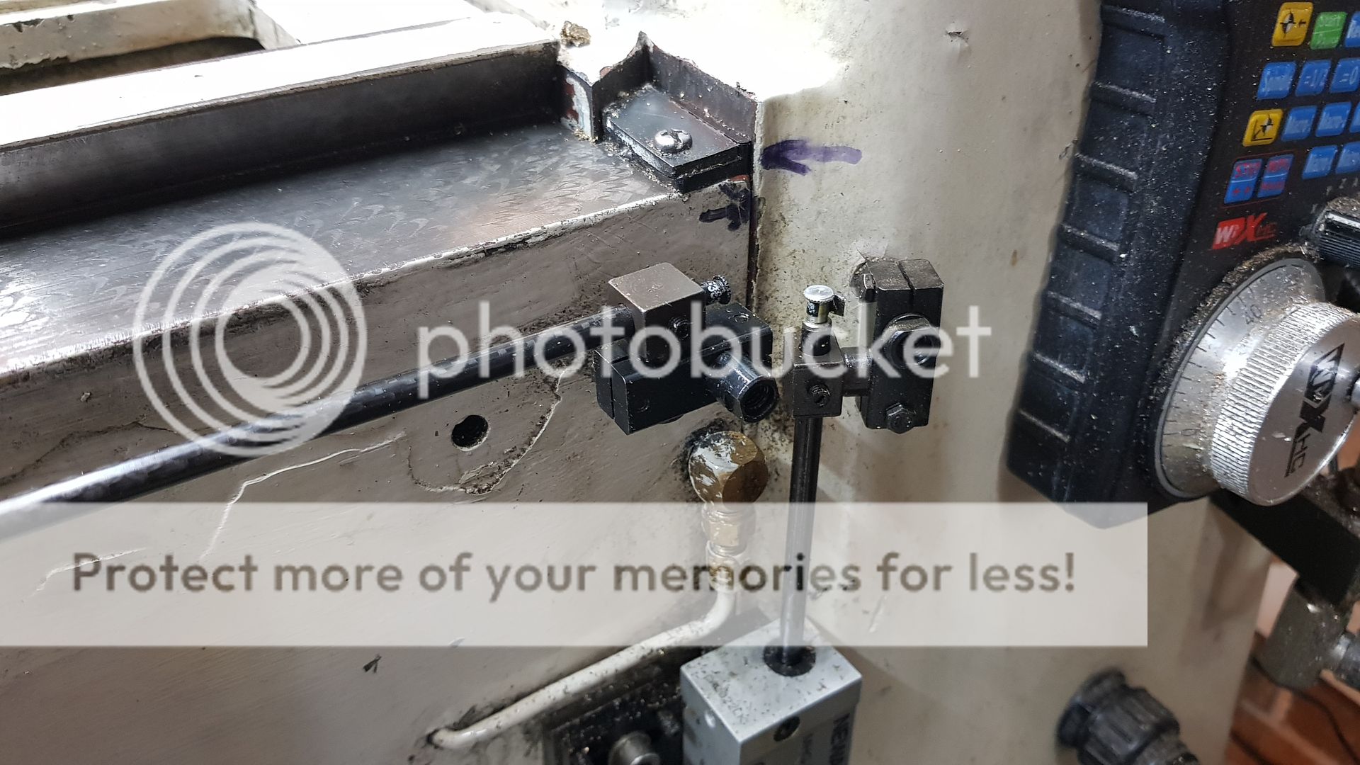  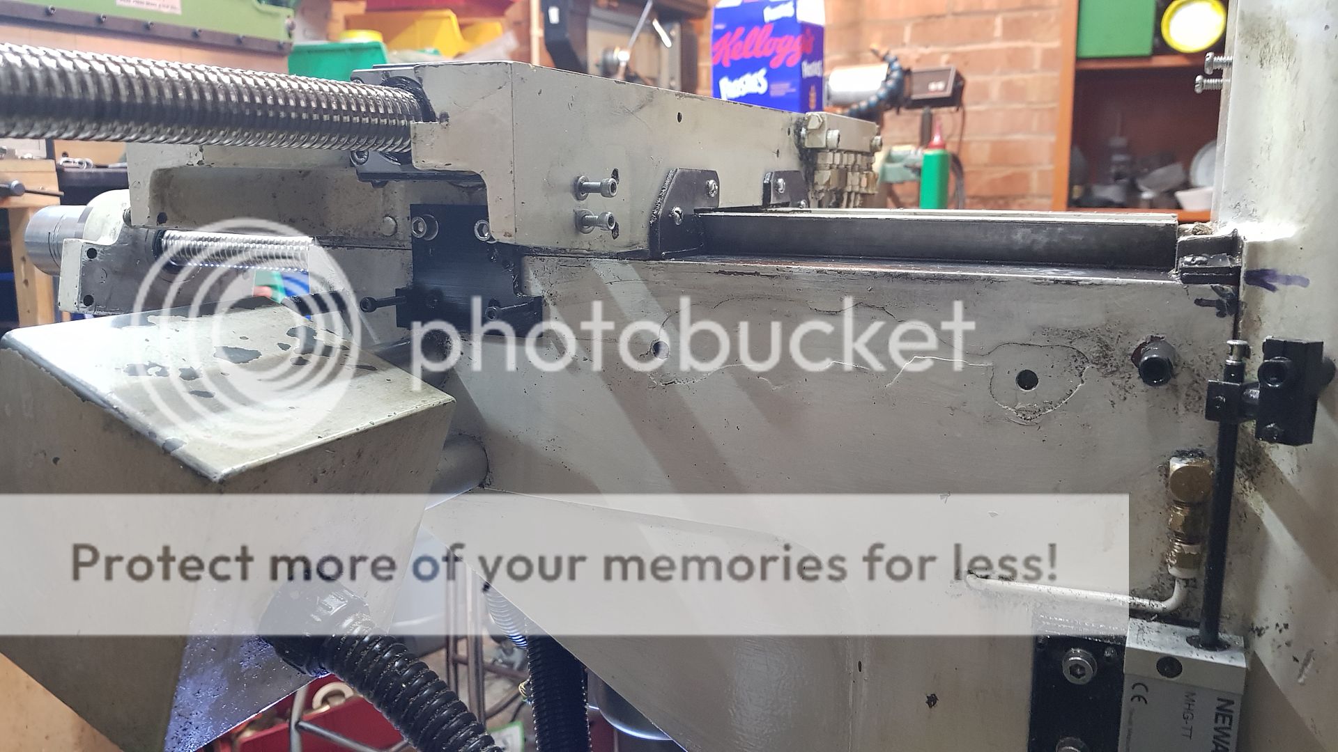 The pulley is keyed onto the end of the leadscrew but it probably doesn't need to be. I tightened the flanged nut up tight and then spotted through for the M4 cap screws that hold the pulley on. 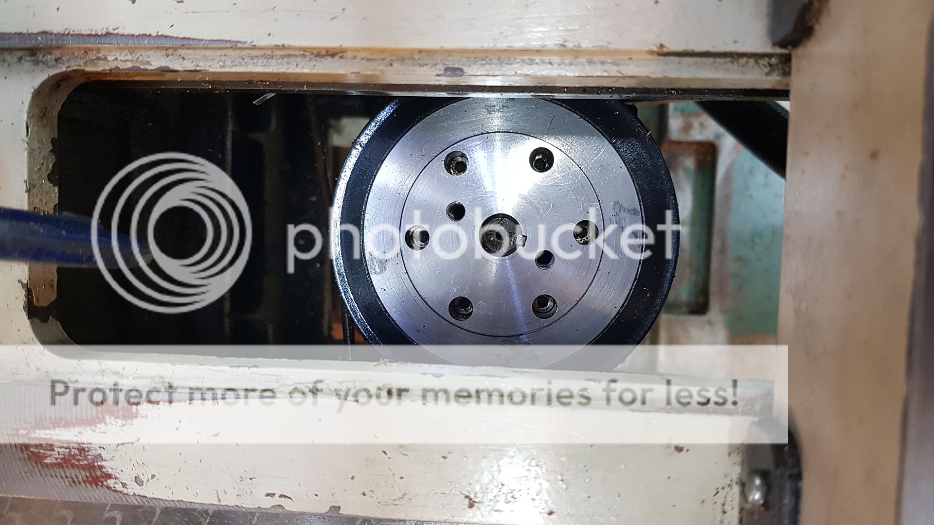 This is how it looks with the pulley and motor removed. The access on this side was where the handle for manually adjusting the knee went with a large cast iron boss. That was replaced with an aluminium plate and bracket to hold the motor. 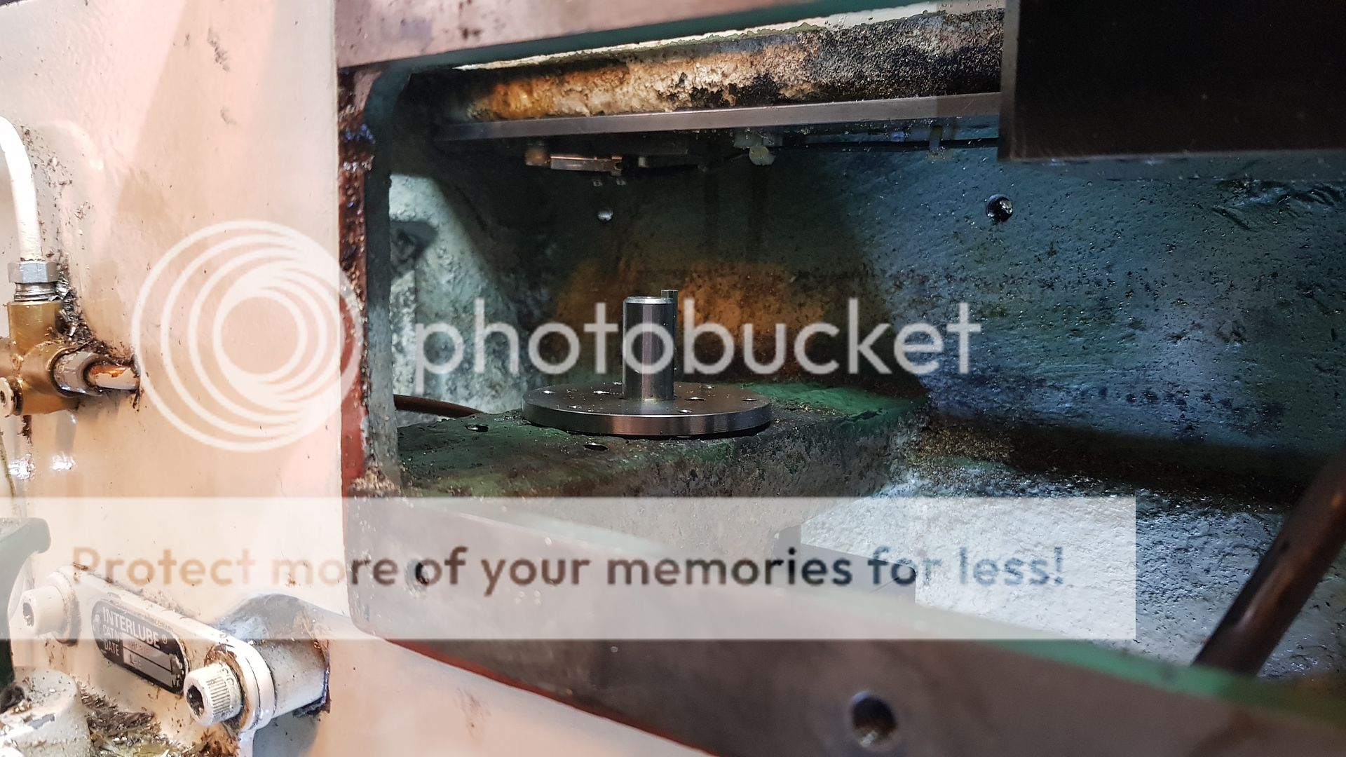 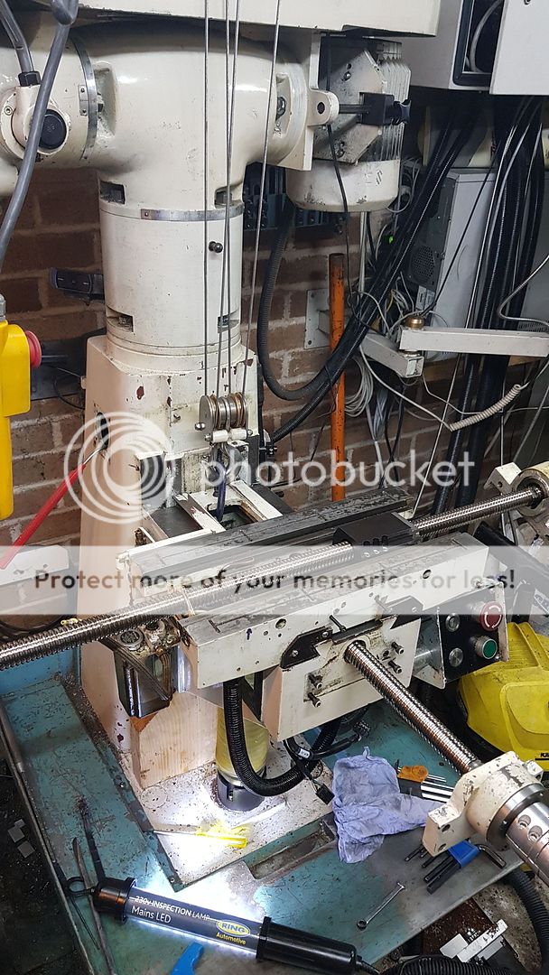 The thrust bearing is on the knee, in the casting which had to be machined to suit. Here is the plate which clamps the outer races into the bearing pocket machined in the knee cross beam. The blue item is a filter to keep dirt out of the bellows which suck and blow each time they move. 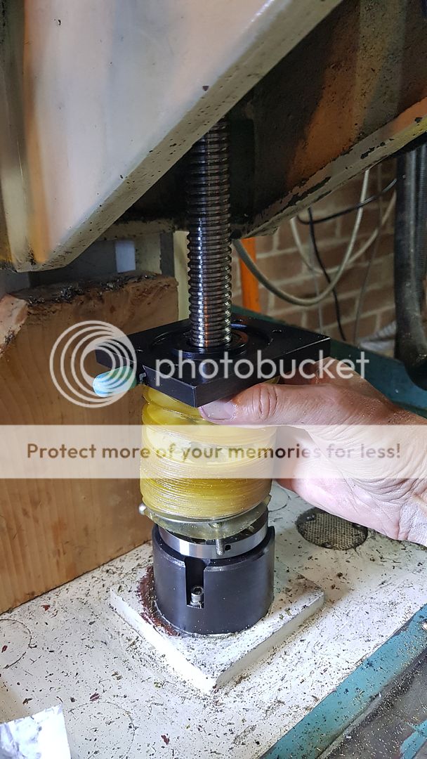 You can see the bottom thrust bearing with the retainer removed. Machining this pocket was a challenge. I did it on a Bridgeport a friend has. 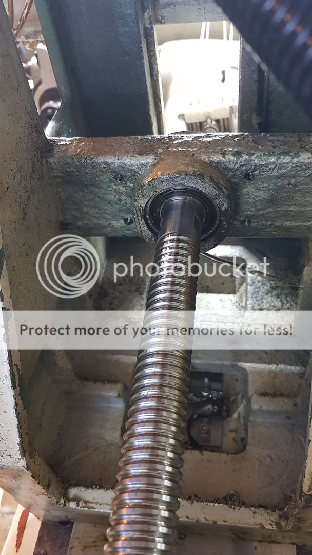 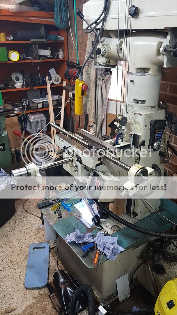 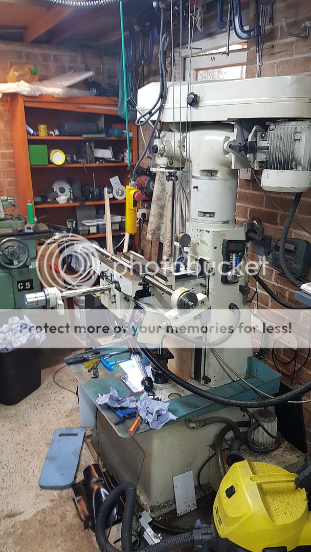 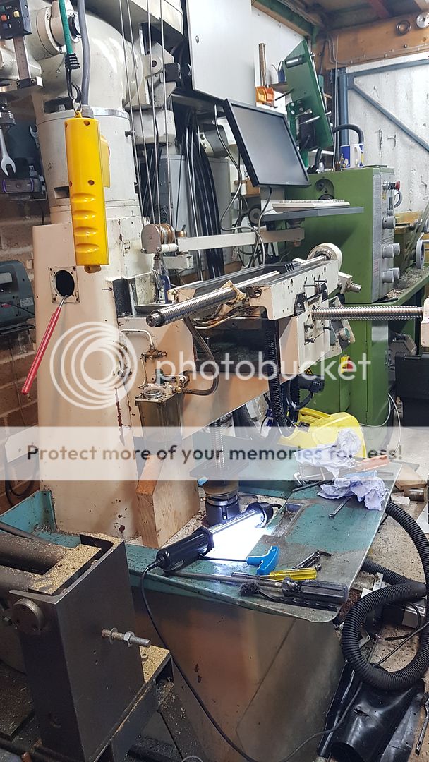 I'd like to remove the thrust bearings for inspection an greasing, but I still can't find that damned spanner! I'm beginning to wonder if I ever made one, but it's unlike me. I simply can't remember, it was done back in 2008 and a lot of water has passed under the bridge since then. So I've used a piece of material that has a handy M10 hole in it to hold the body of the tool so I can add the two 5mm dowel holes. Here I'm clocking it to get it on the centre line of the chuck. I can spin the chuck right round and adjust the quick change tool post to get it at the right height. 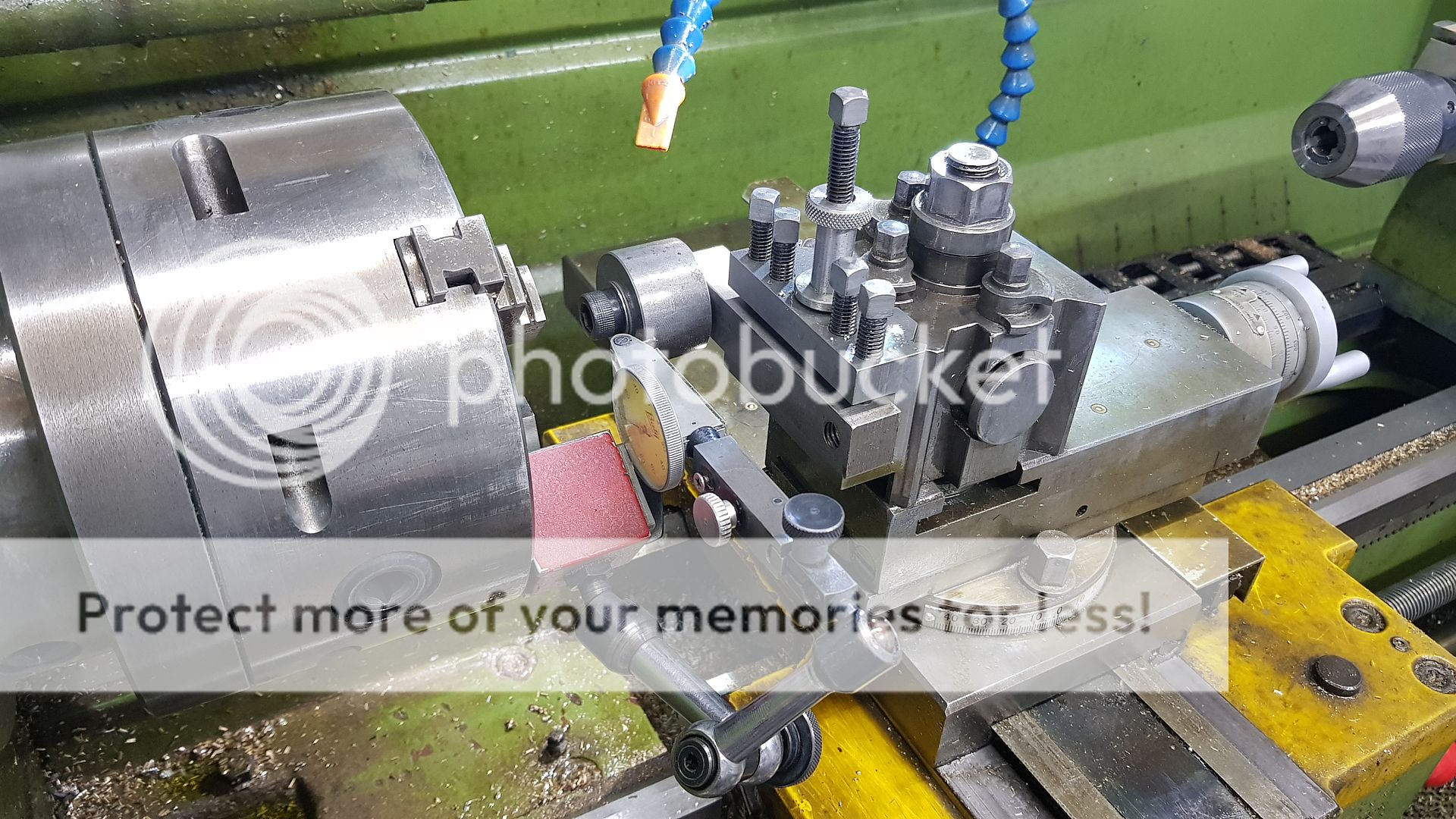 Then it's just a matter of zeroing the DRO and winding the cross slide both sides of the tool to add the holes. 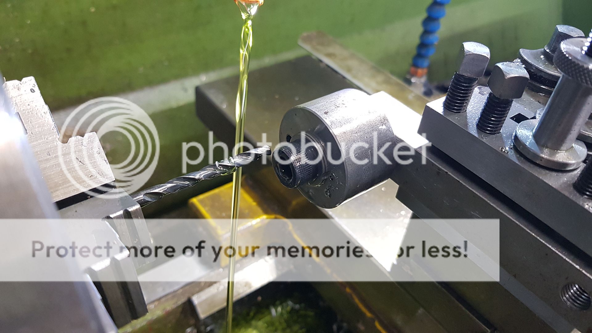 A similar idea was used to hold the tool so I can drill and ream the handle hole. 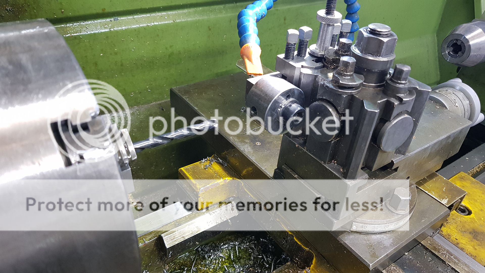 It fits really nicely, so I'm pleased about that. The same tool is used for all three axes. 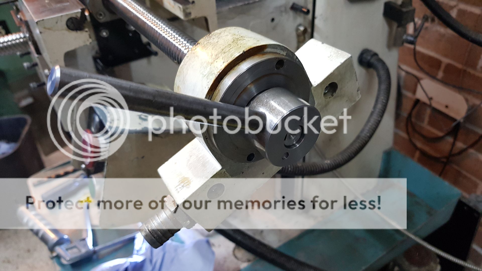 The pins are just short lengths of Silver Steel. 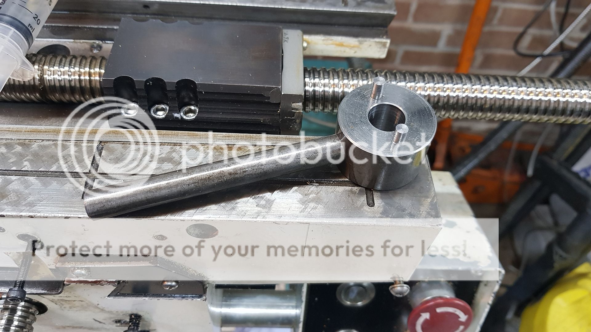 More tomorrow when hopefully I'll find out what's causing the problem with the Z-axis. |
|
timo
E-xcellent poster
   Completing 3 1/2 Rainhill .Building 5" Railmotor and waiting to start 3 1/2" King
Posts: 234
|
Post by timo on Aug 8, 2019 8:35:03 GMT
That is both an impressive bit of kit and conversion. I hope you find the problem.
Tim
|
|
|
|
Post by Roger on Aug 8, 2019 11:58:51 GMT
That is both an impressive bit of kit and conversion. I hope you find the problem. Tim Thanks Tim, I think it's just a matter of lubrication and adjustment. It's clearly worn, but with a little TLC I think it will be ok. I'd forgotten how much work I'd put into the conversion, all the Servo mounts and thrust arrangement and hiding limit switches etc. I wanted it to look neat and tidy so it would be easier to keep clean. I did this before I had the crane, just using a borrowed engine hoist. The crane makes this sort of thing easy, even though the parts are pretty heavy. Bizarre as it might seem, the crane is the best thing I've made, I'd be lost without it. |
|
|
|
Post by racinjason on Aug 8, 2019 21:36:29 GMT
Roger,
What size ball screws are you using on the three axis.
Cheers Jason.
|
|
|
|
Post by Roger on Aug 8, 2019 22:05:33 GMT
Roger, What size ball screws are you using on the three axis. Cheers Jason. Hi Jason, They're 25mm diameter and 5mm pitch ground precision ones. I bought the X and Y ones from THK as follows... THK DIK2505-6WWG0+892LC3J2K X-axis £686.31 THK DIK2505-6WWG0+436LC3J2 Y-axis £544.50 The Z-axis one is one that I already had. I'd have used all three from my stock but they wouldn't fit the other axes because the ball nut dimensions are way too big. The THK ones as much smaller. These are 2008 prices so heaven knows what they would cost now. The original quote for three axes and the thrust bearing housings was over £2300. I saved a lot by modifying the existing simple bearing housings at the thrust end to accept a pair of angular contact bearings back to back. These have to be a matched pair. Again, these can be very expensive, but I already had them as a service part for the machines I support. The problem with converting a manual machine is that the conventional ball nuts are very compact compared to recirculating ball types. I wanted to use the largest possible diameter so it would be as stiff as possible. I knew that size was good for the size of machine I've got because that's what was on the CNC Drill/Routers I support and had a hand in designing. The same goes for the motor sizing. I chose something with an equivalent performance to the huge DC Servos on those old machines. We had already converted the Z-axis on some of those machines to AC Servos from the old Shell armature low intertia motors, so I knew they would be more than capable. |
|
|
|
Post by racinjason on Aug 8, 2019 22:42:21 GMT
Thanks Roger,
I just downloaded THK manual I'll have a look at it more tonight.
Cheers Jason.
|
|
|
|
Post by Roger on Aug 8, 2019 22:47:16 GMT
Some more photos of various bits and pieces now I can get a better look at them.... This is looking through the underside of the knee, showing the slotted mounting for one of the Z-axis limit switches. You have to move the knee to this position to adjust it. Fortunately that's only necessary when building the machine for the first time. 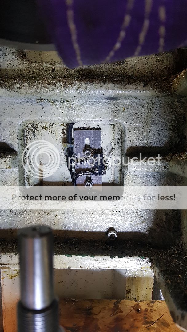 With the knee moved clear of the switches, you can see how they're arranged. 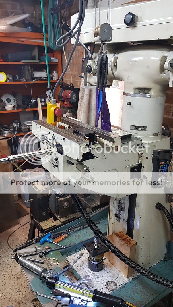 Th e X-axis limit switches are also tucked neatly away. 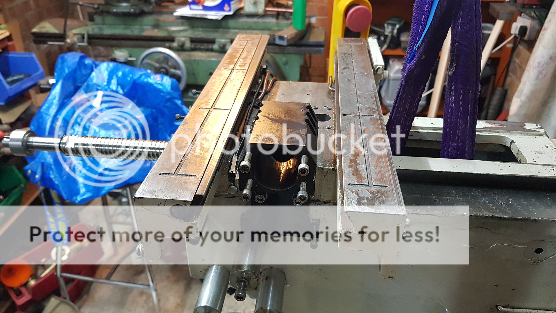 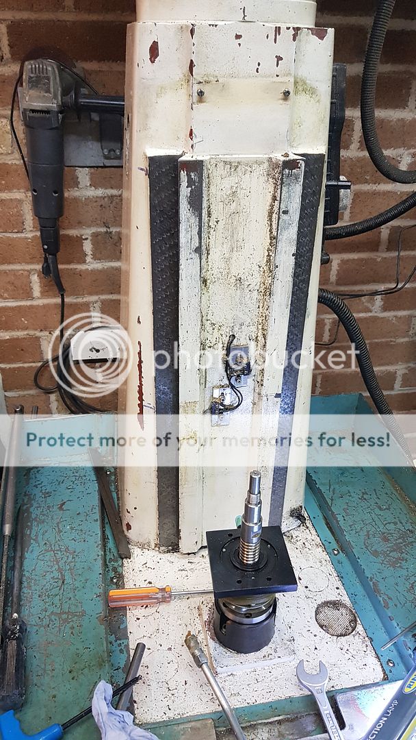 The Z-axis limit switches are actuated by a M5 cap screws, you can see the top one on the RH side of the picture near the camera. There's another one on the other end of the casting, obscured by the Photobucket watermark 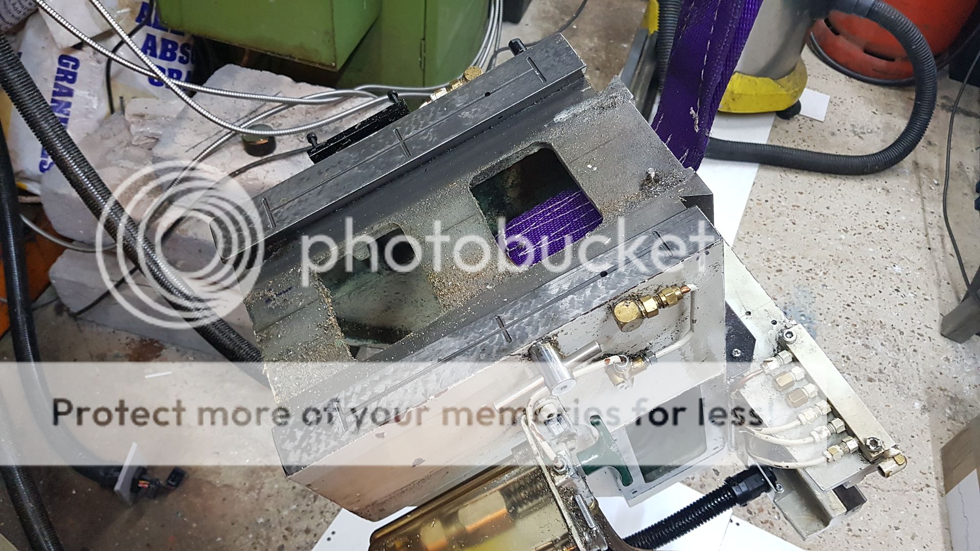 The Z-axis limit switches. These are sealed types to keep the oil out. 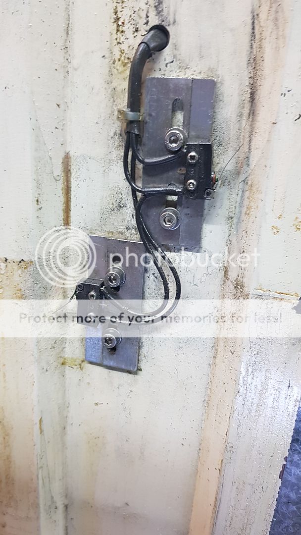  The Z-axis gib strip has worn away some of the scraping marks in places, so I added a few shallow ones across the offending area in an attempt to encourage oil to stay in there. 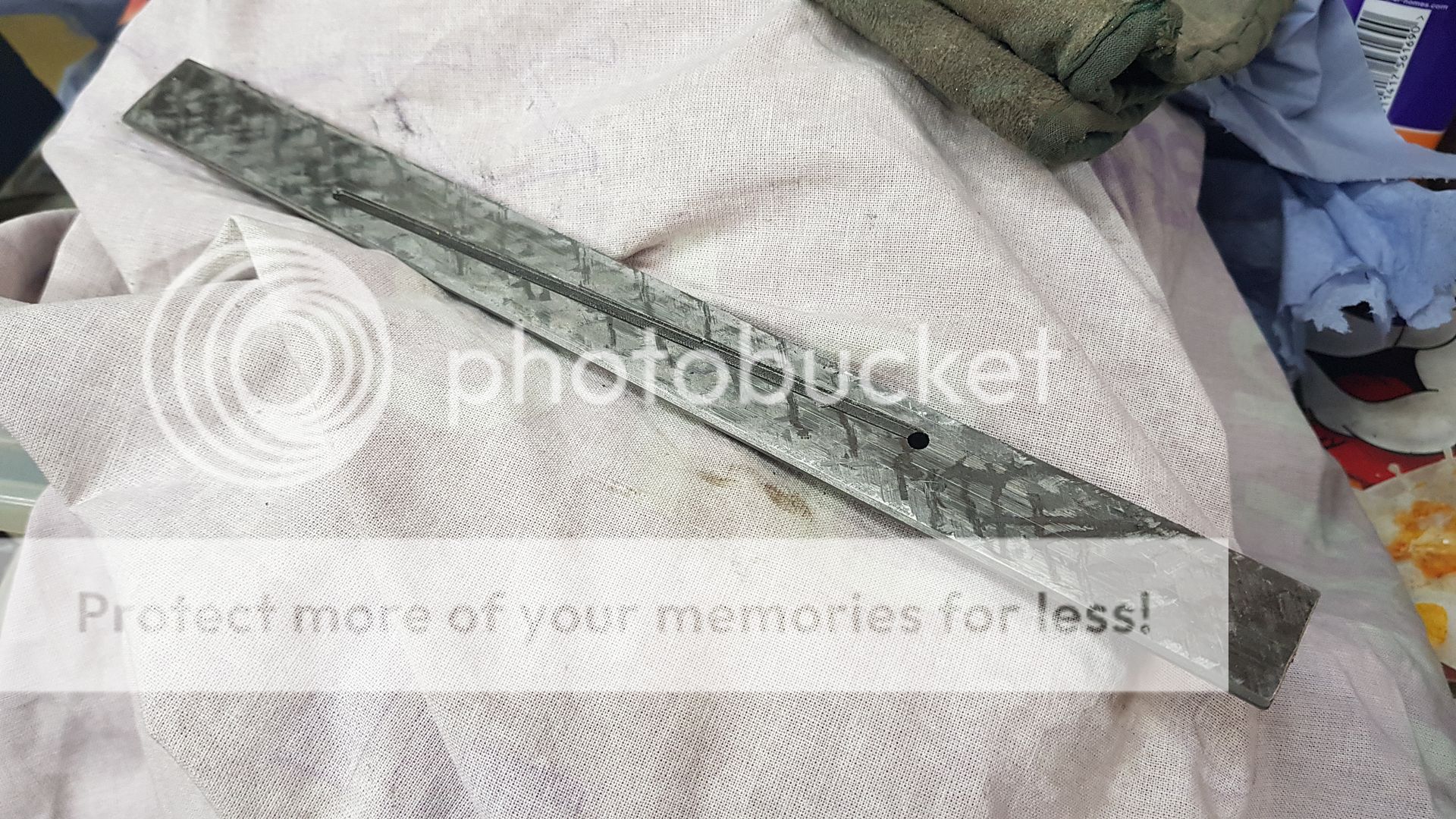 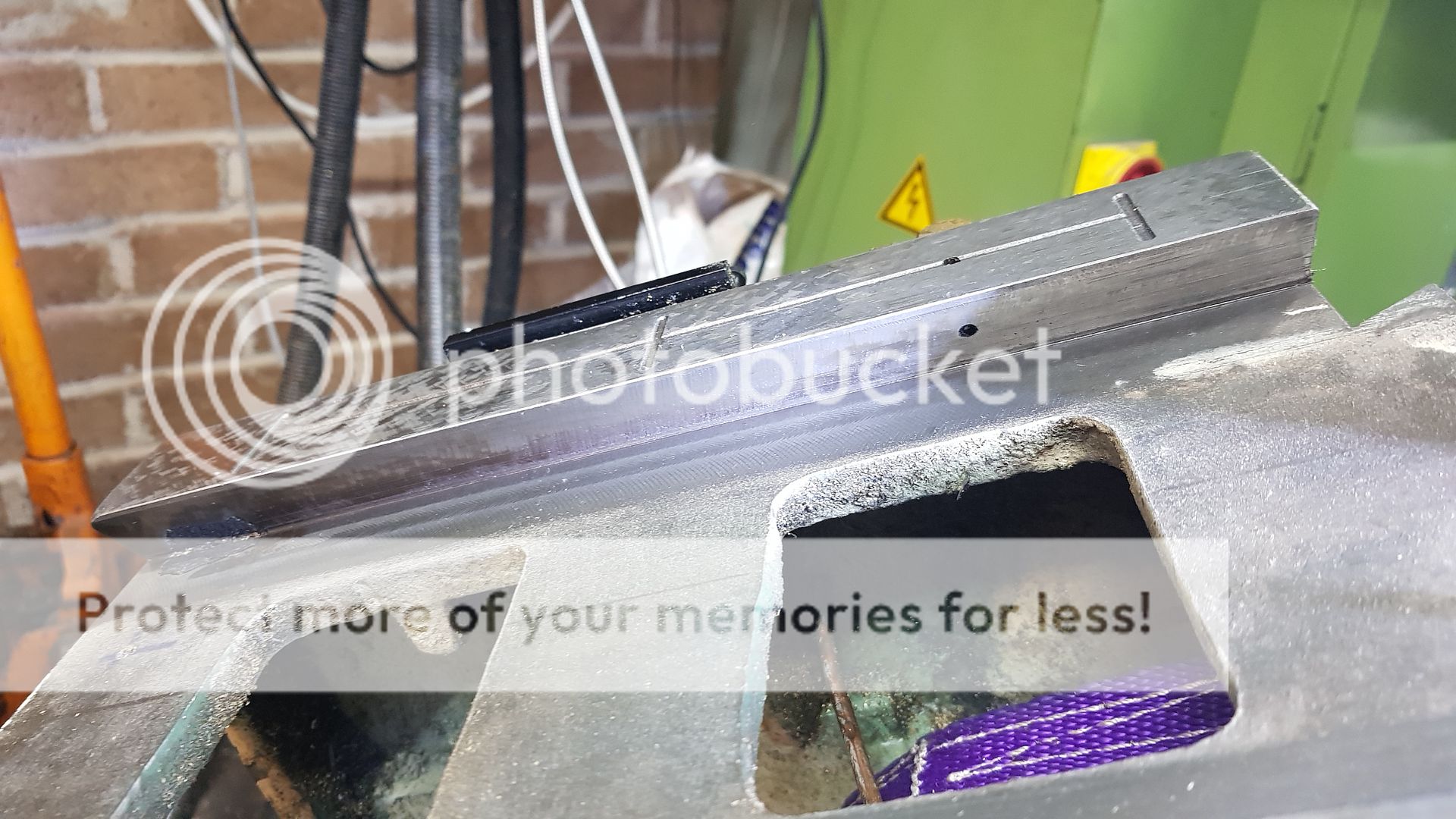 The dodgy casting was like that when I converted the machine and doesn't seem to have got any worse.  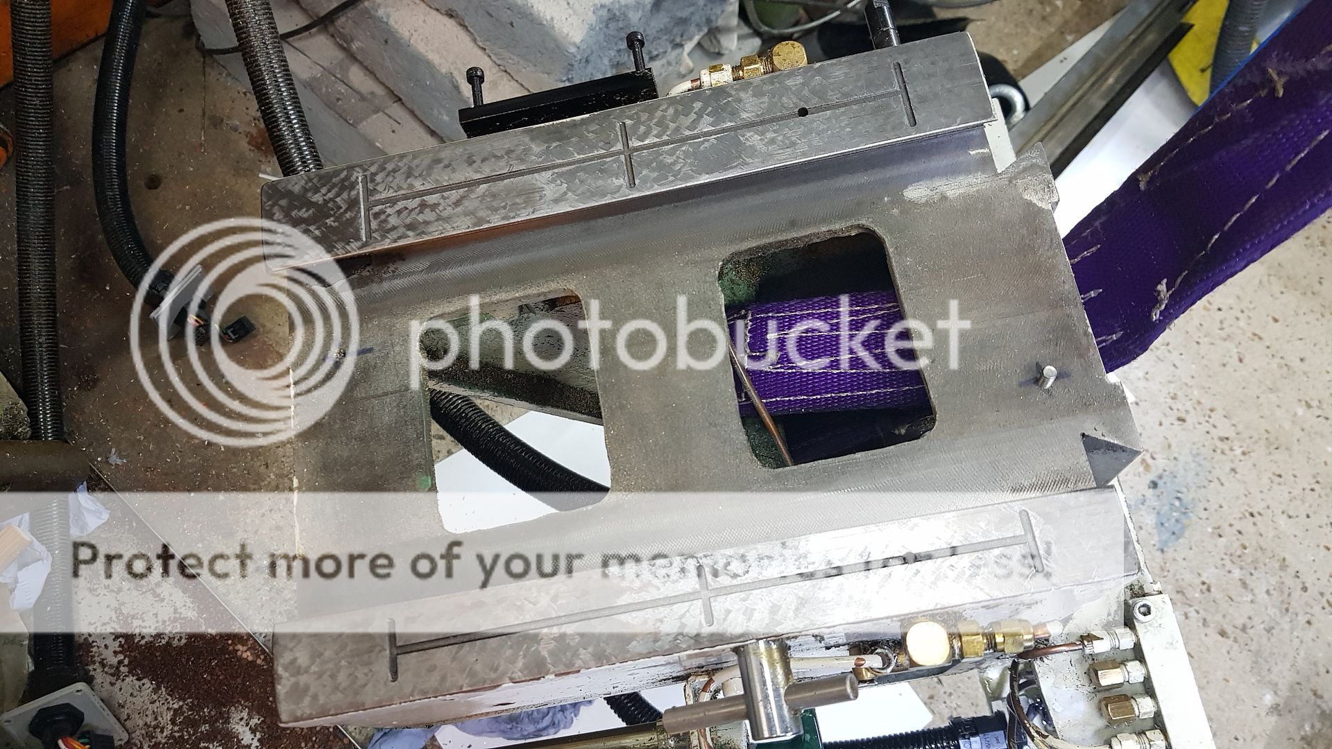 Again, I've made a custom leadscrew ball nut housing to suit the machine. The actuator block for the Y-axis limit switches is screwed to the side of it. 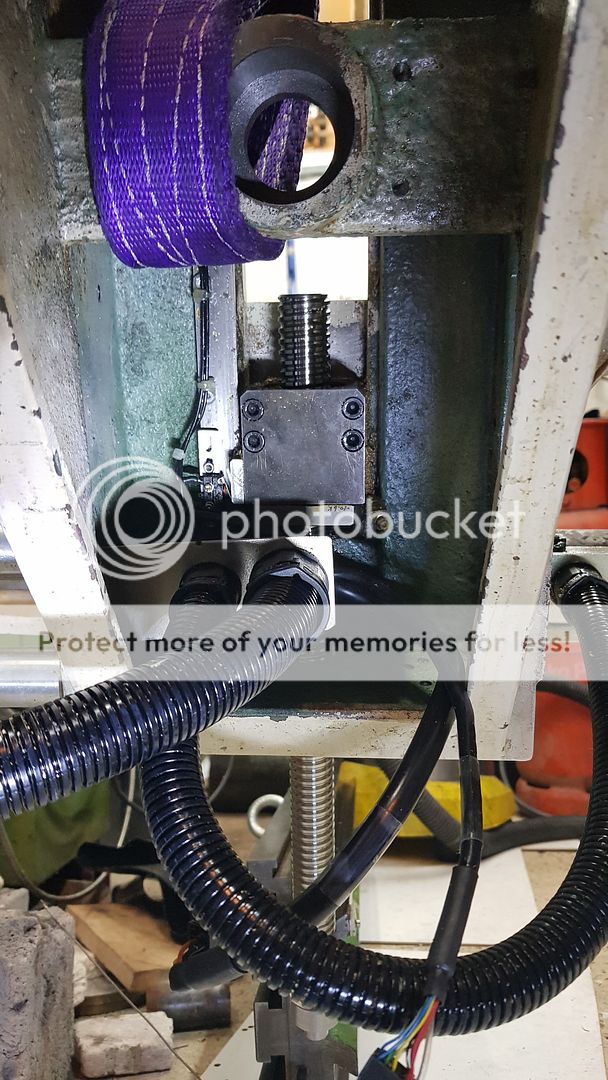 You can get to the greasing point because I made a custom nipple extender to fit the ball nut. Unfortunately, the same isn't possible on the X-axis, there isn't room for one. On the X-axis, you have to unscrew the four cap screws holding the ball nut in place and slide the whole table to the left to leave the ball nut exposed. Only then is it possible to screw in a grease nipple and grease it properly. I tend to smear a little grease next to the nut from time to time instead. 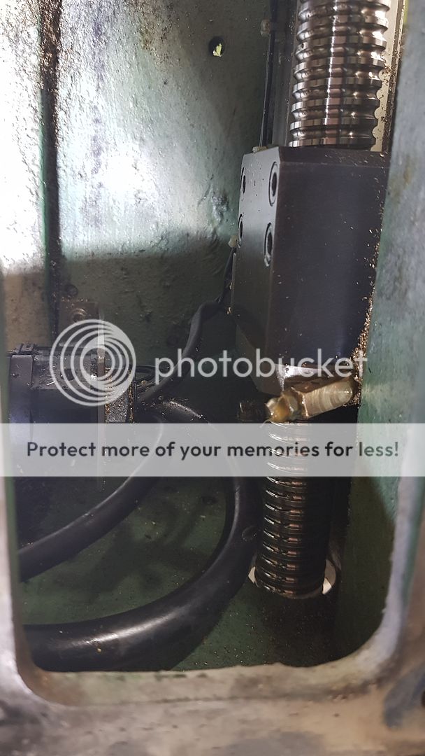  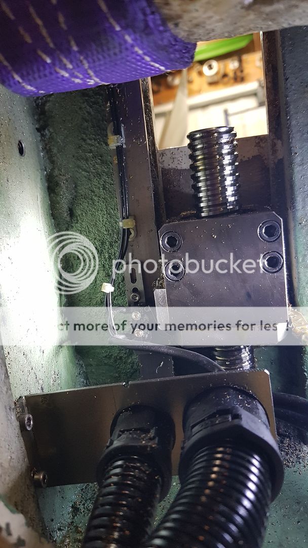 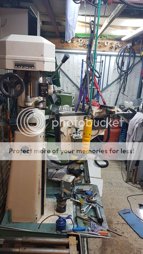 Anyway, it's starting to go back together now, I didn't find anything nasty had happened. The leadsrews and thrust bearings are in great shape, still greased and silky smooth. |
|
timo
E-xcellent poster
   Completing 3 1/2 Rainhill .Building 5" Railmotor and waiting to start 3 1/2" King
Posts: 234
|
Post by timo on Aug 9, 2019 9:22:25 GMT
Roger,
Mind duly boggled! No wonder you are able to produce items like the loco cab windows.
Tim
|
|
|
|
Post by Roger on Aug 9, 2019 21:44:25 GMT
Some of the oiling points aren't working as well as they should, so I've been scraping out what looks like white Silicone rubber from the inside. Whether that was ever intended to be some part of the regulating units or not is unclear, but it's certainly not helping the oil get through. These look like they have a sintered Brass or Bronze insert to filter and regulate the delivery. I made the fitting to go on my air line so I could force air or oil through them for a test. 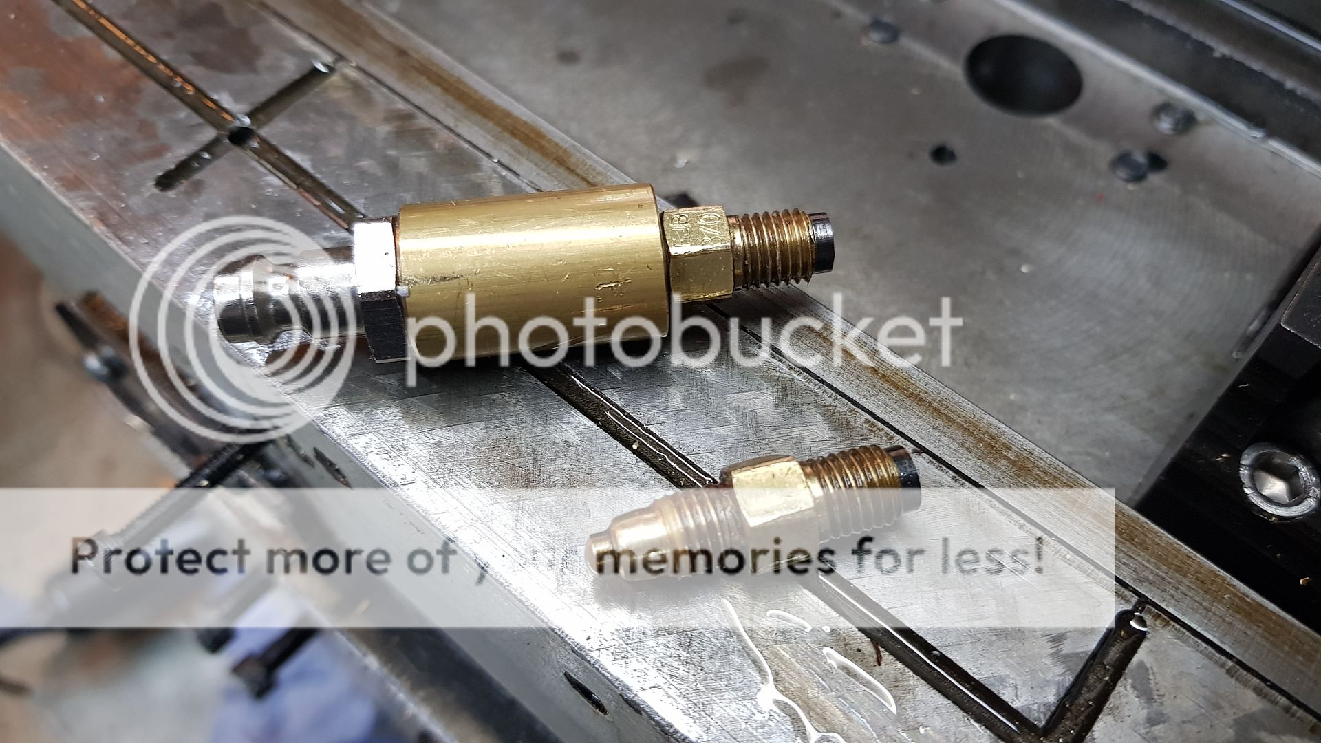 The Z-axis motor has a 2:1 reduction, but that makes it a challenge to attach the toothed pulley to the 15mm plain shaft. The solution I adopted was to bore a taper right through the aluminium pulley and make a matching split tapered bush that's pulled into the pulley with three cap screws. Here you can see the difference between the X/Y motors and the Z-axis one. The Z-axis has an extra DC Brake module which is released by the SureServo amplifier is enabled. This is necessary because the leadscrew is a rolling contact and the table sinks rapidly under its own weight as soon as the Servo is disabled. 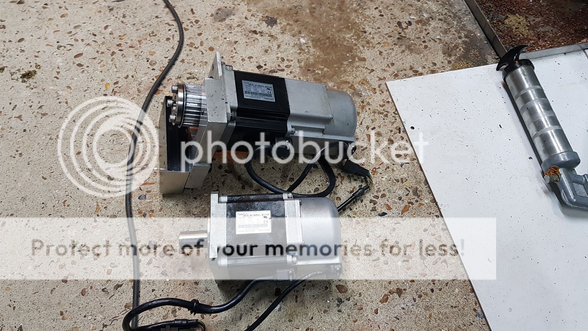 You can see how snugly the Z-axis Servo arrangement is. That was the most difficult part to figure out when doing the conversion. There's very little room between the belt drive and the mounting for the Y-axis ball nut housing, hence the need for a compact way to attach the pulley to the motor. You can see some damage to the pulley teeth from swarf that's made its way down there. 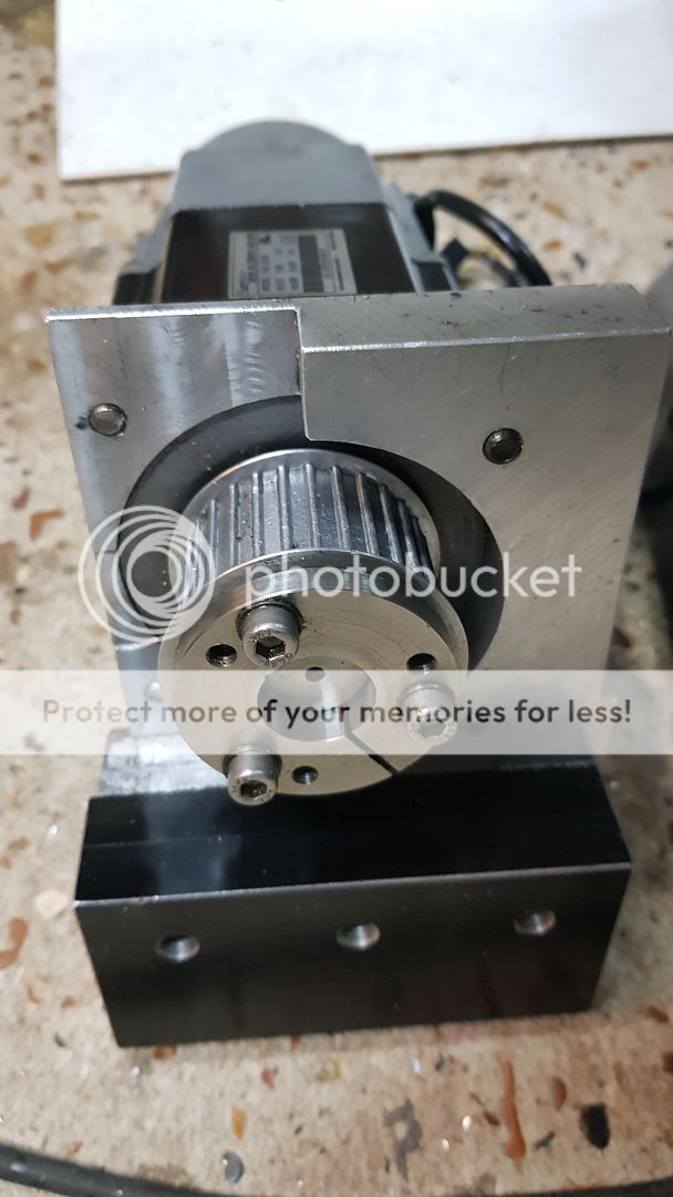 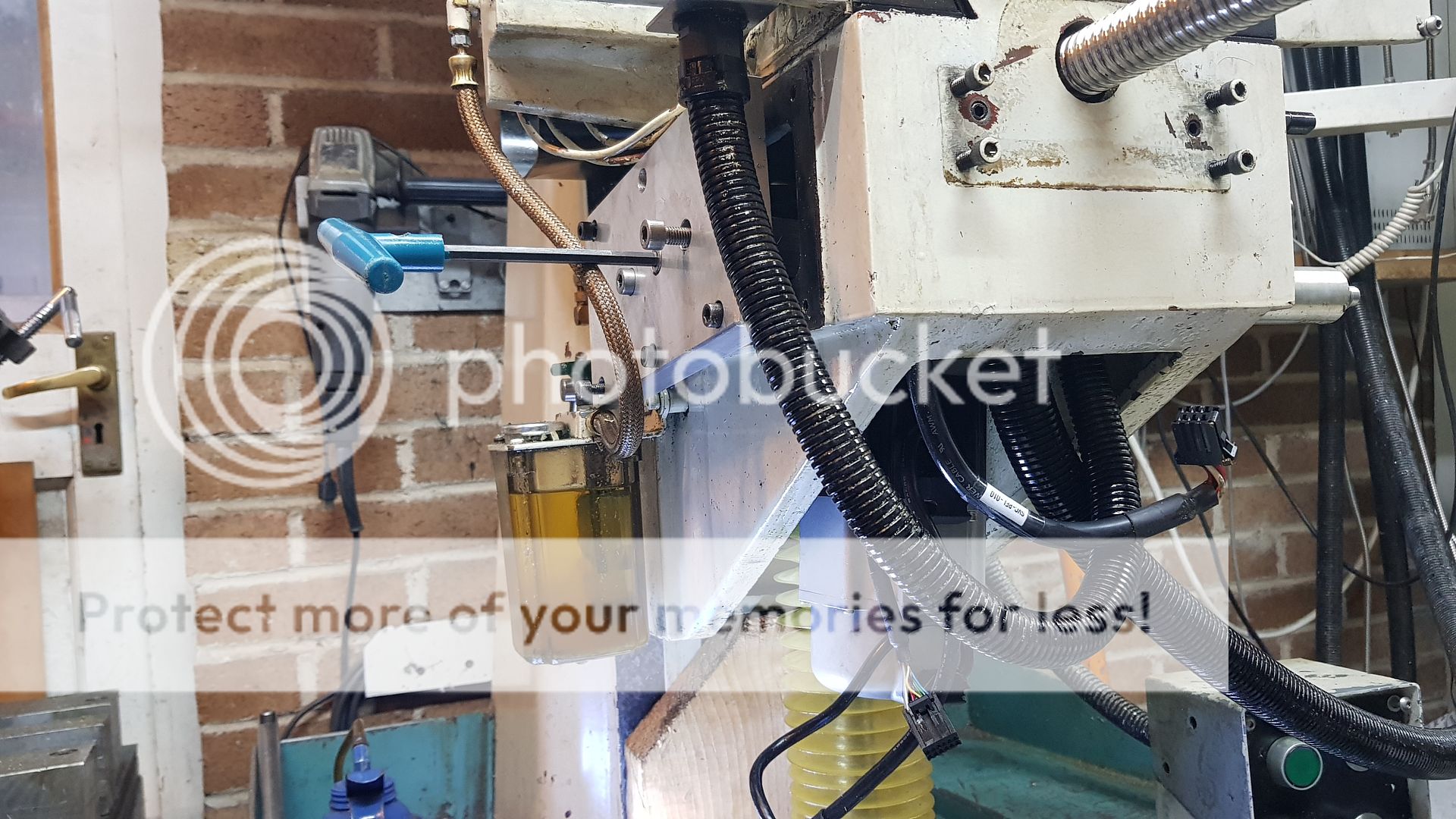 The X and Y-axis thrust arrangement is identical, this one is the Y-axis. There's a pair of angular contact bearings back to back and two spacers that have oil seals front and back. 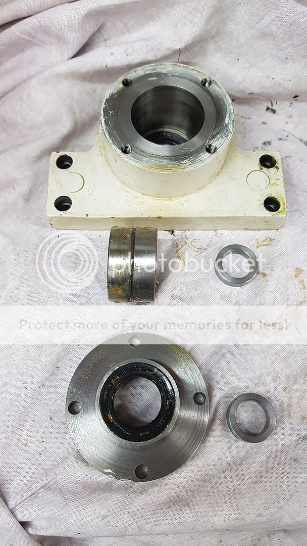 The bearings are supplied as matched pairs, and here you can see the position of the maximum runout measured in microns. There's an alignment triangle etched on the outer to show you which is the best way to align them to get the minimum rounout. To be honest, this isn't that critical in such a crude application, but it's absolutely vital to do this if you're fitting them to a 60,000 RPM spindle! Failure to so this will cause vibration, excessive runout and it probably wouldn't be possible to run it in to the maximum RPM without the balls bouncing off their tracks and wrecking the bearing. 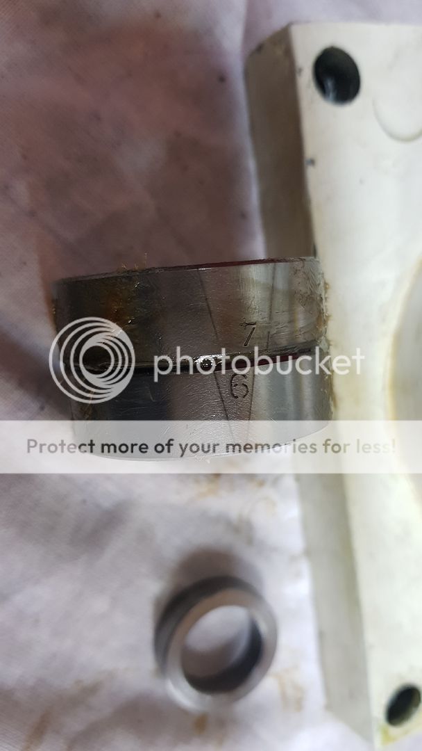 The inner bearings are tightened first... 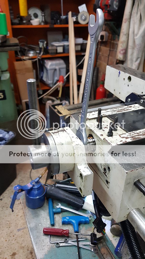 ... and then the outer races are clamped by the Aluminium motor mount and the pocketed retainer. The coupling has to go on first else the cap screws can't be done up. 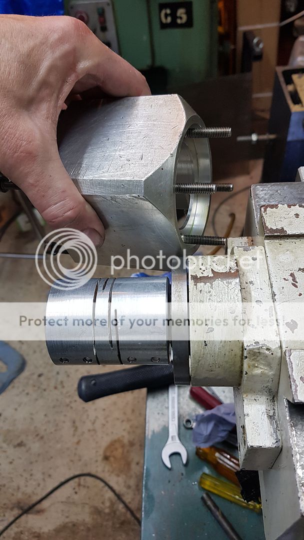 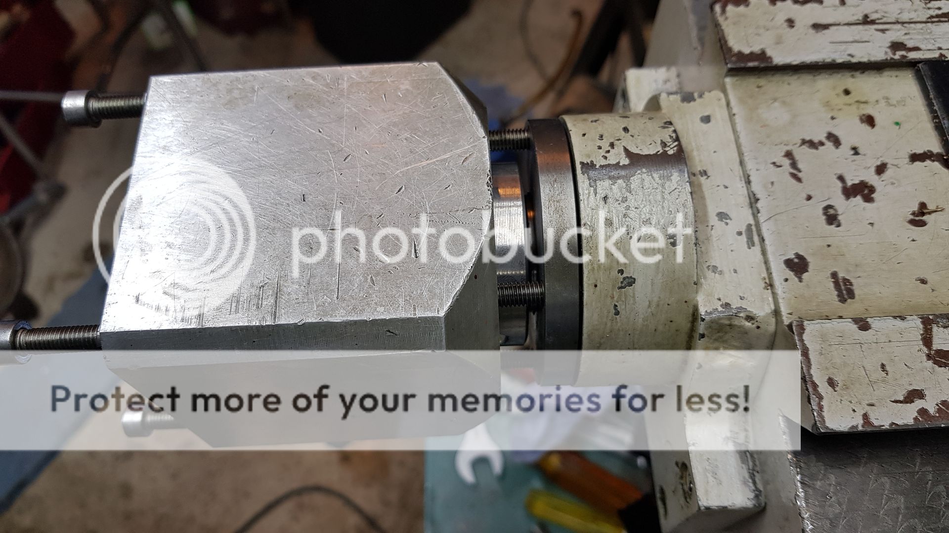 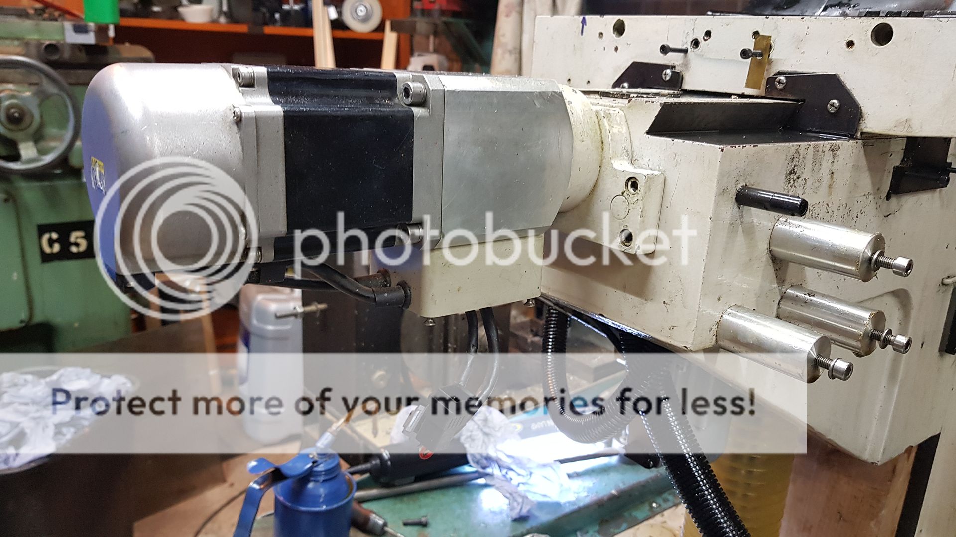 This is the arrangement to allow for adjustment of the encoder using the grub screws on the corners of the plate.  I'm putting them back on even though they're not used at the moment. 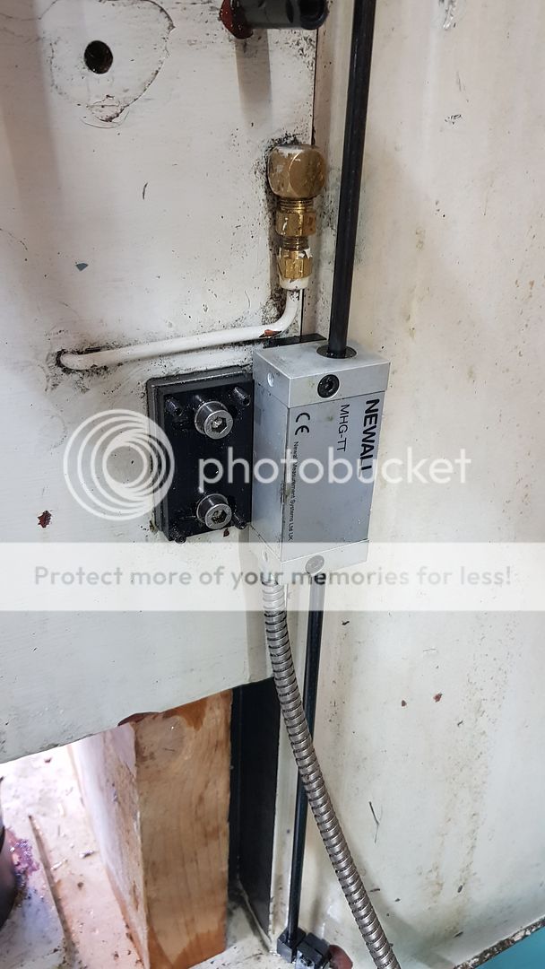 Newall use these clamping posts which are excellent. You leave them loose and then carefully move the axis to the extreme end of the travel and nip them up. The off looking piece at the end tensions the balls against each other inside, you must not change its position else the calibration is lost. 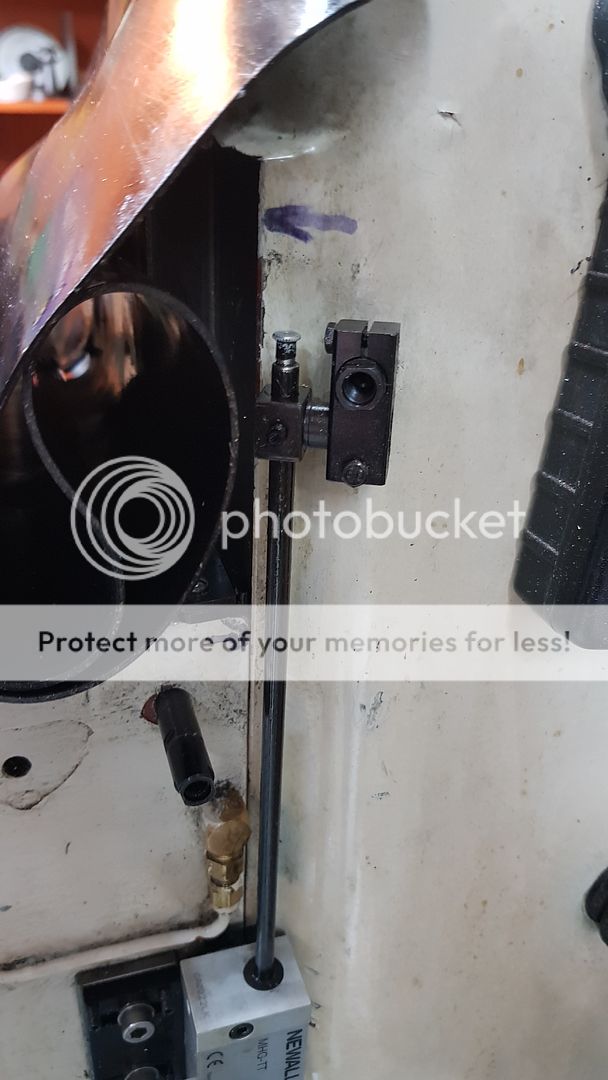 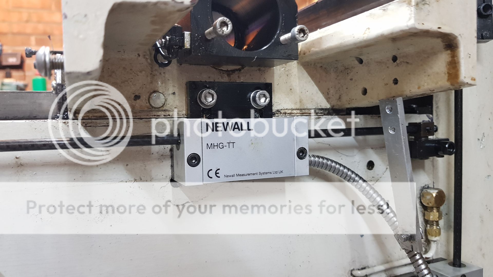 You can see that I had to take the grinder to even this small flange on the Recirculation Ball leadscrew nut... 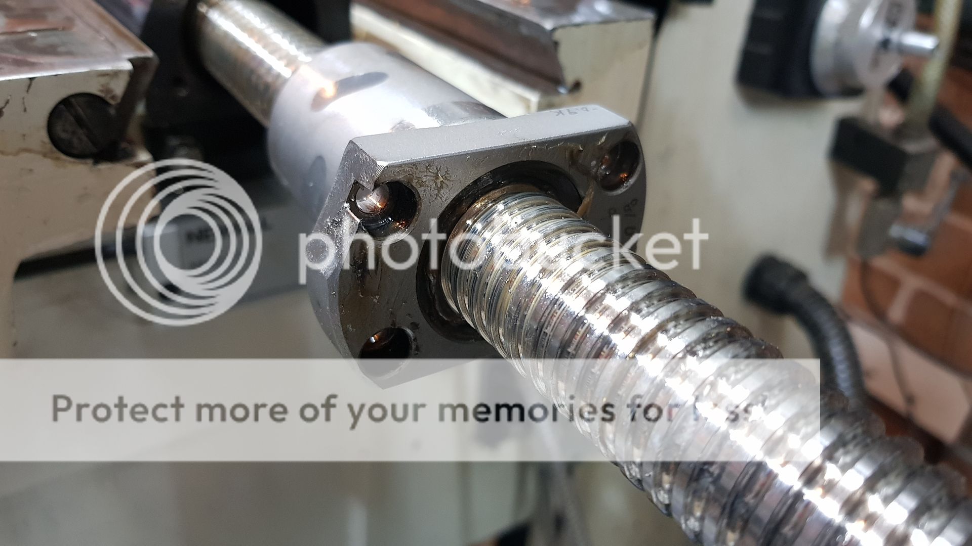 ... and some of the X-axis mount had to be relieved to clear the inside of the table too. 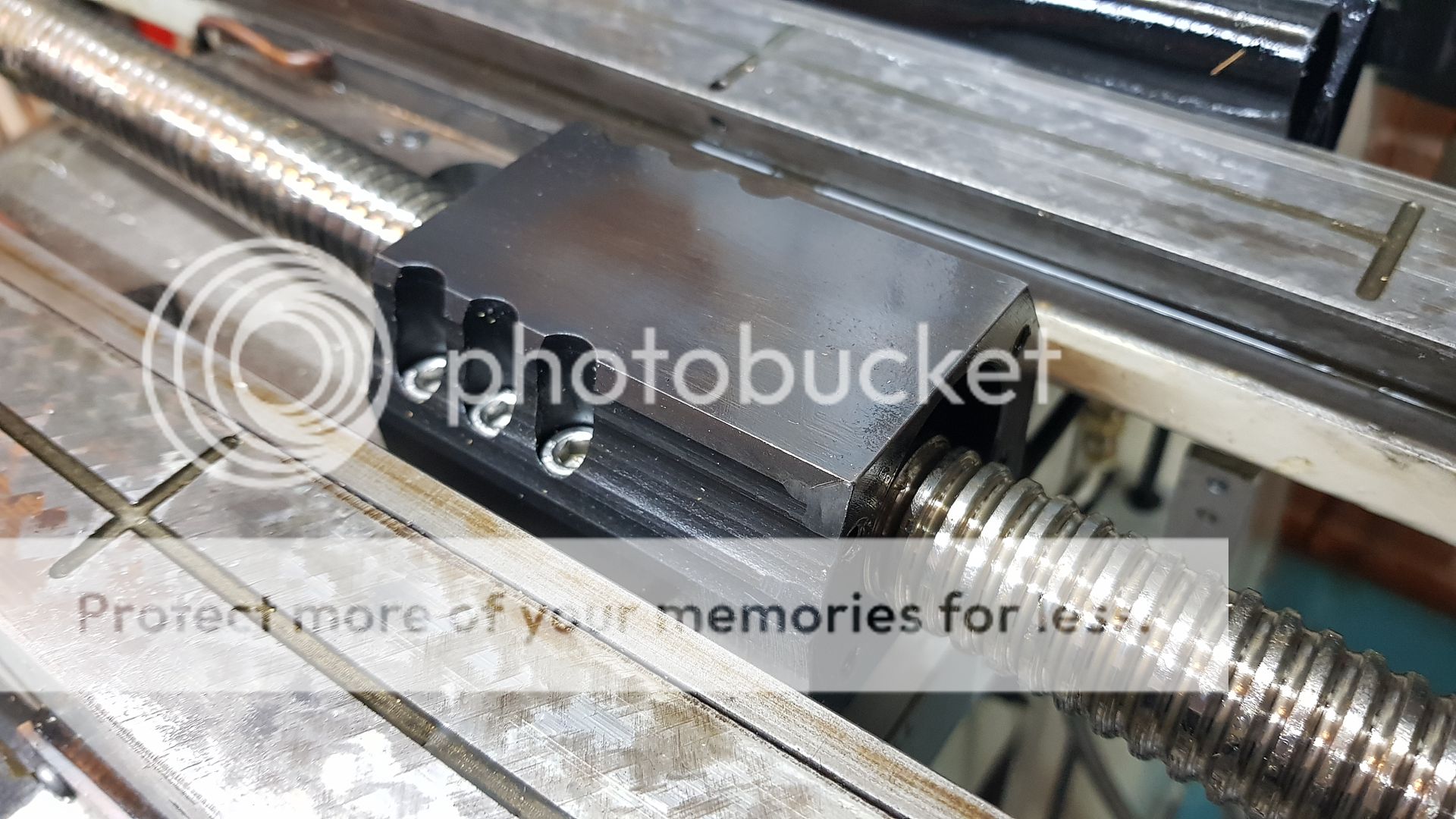 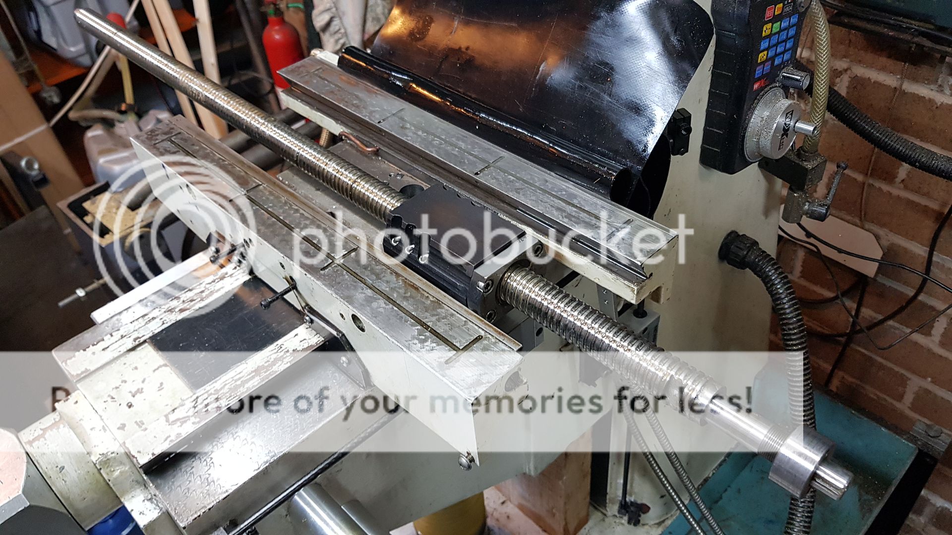 The X-axis table looks reasonably good, so I've just cleaned that. 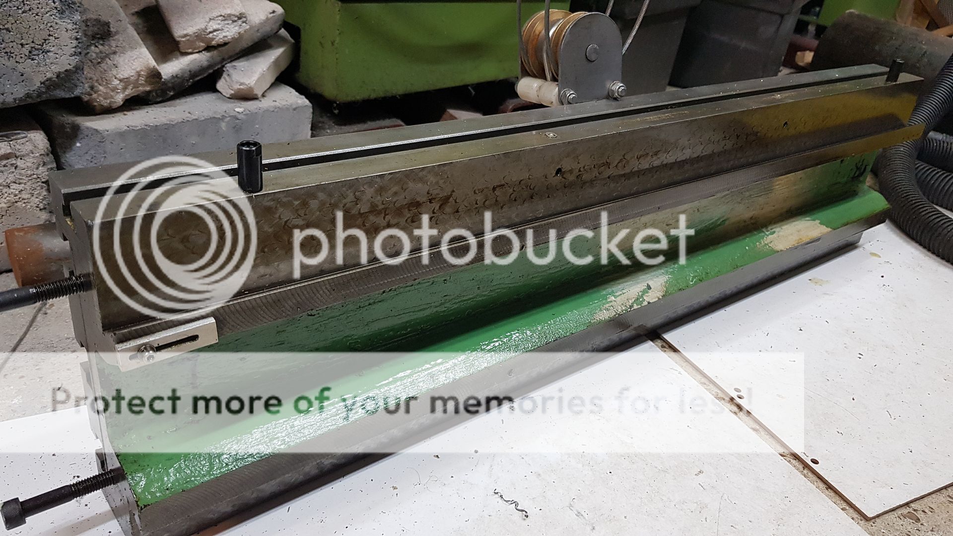 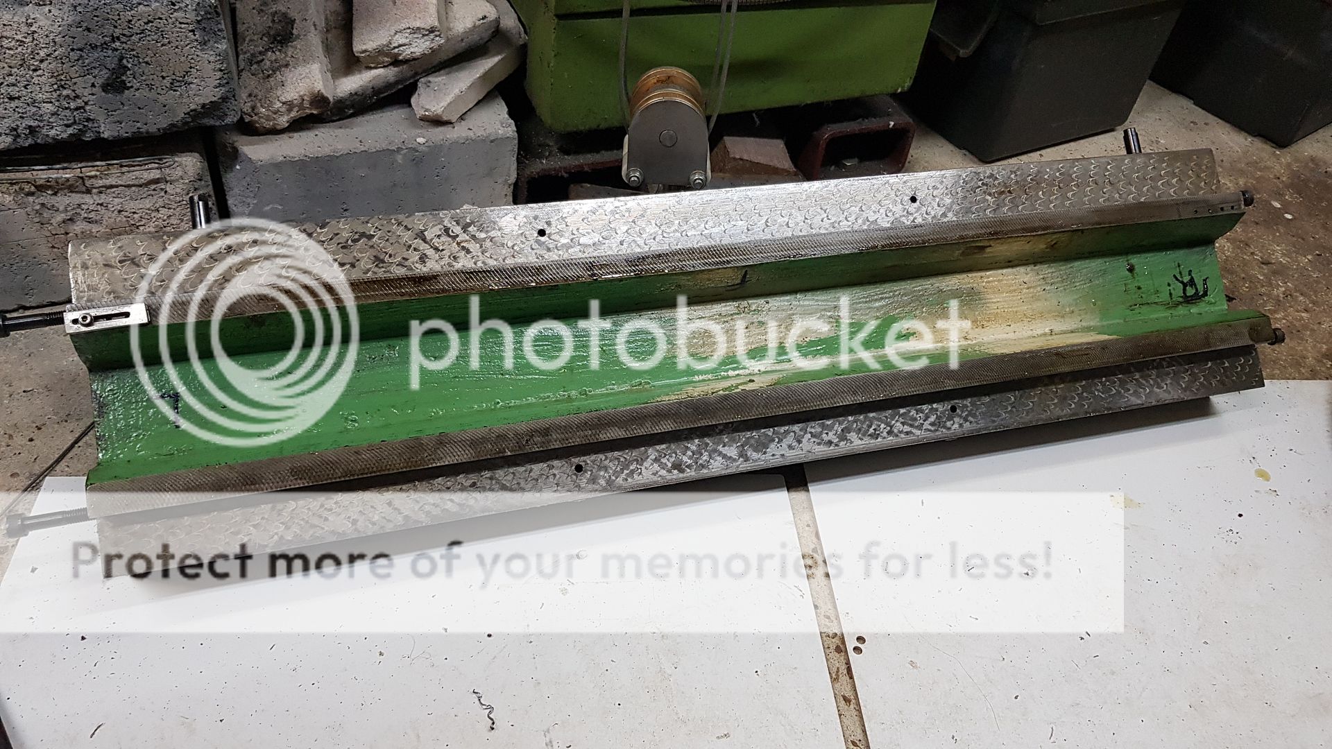 Here I'm offering the slides to each other so I can set the crane to the right height. I've just used a Tee nut and M12 lifting eye, moved to the balance point. 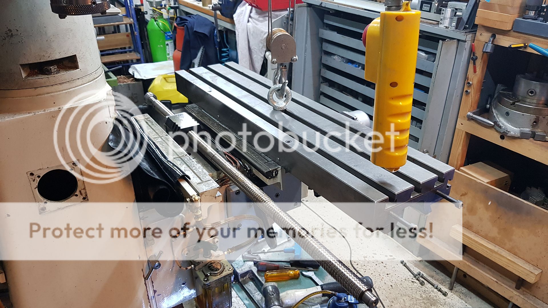 This end just slips on the shaft. There's nothing to stop the bearing from coming out, but it hasn't in ten years so I'll leave it be. 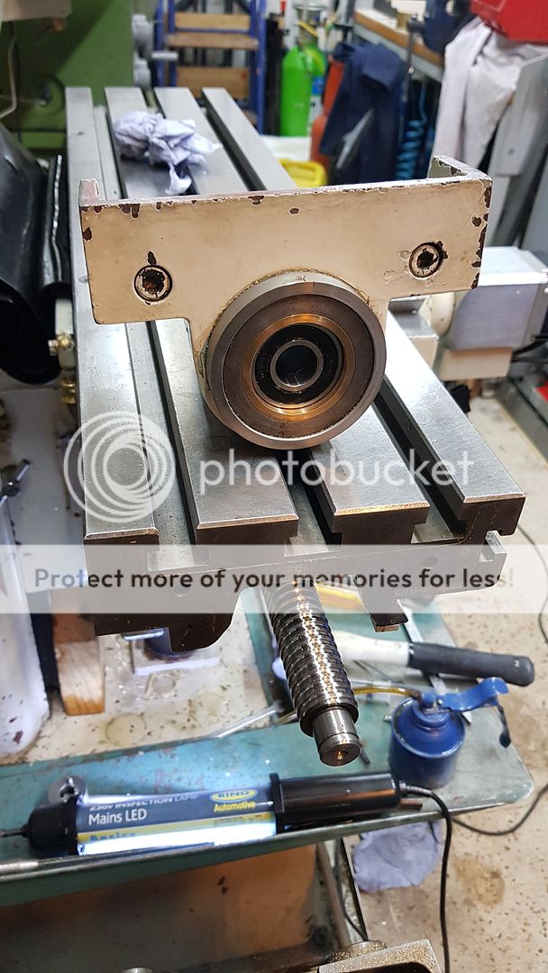 The X+ actuator now can go back on. 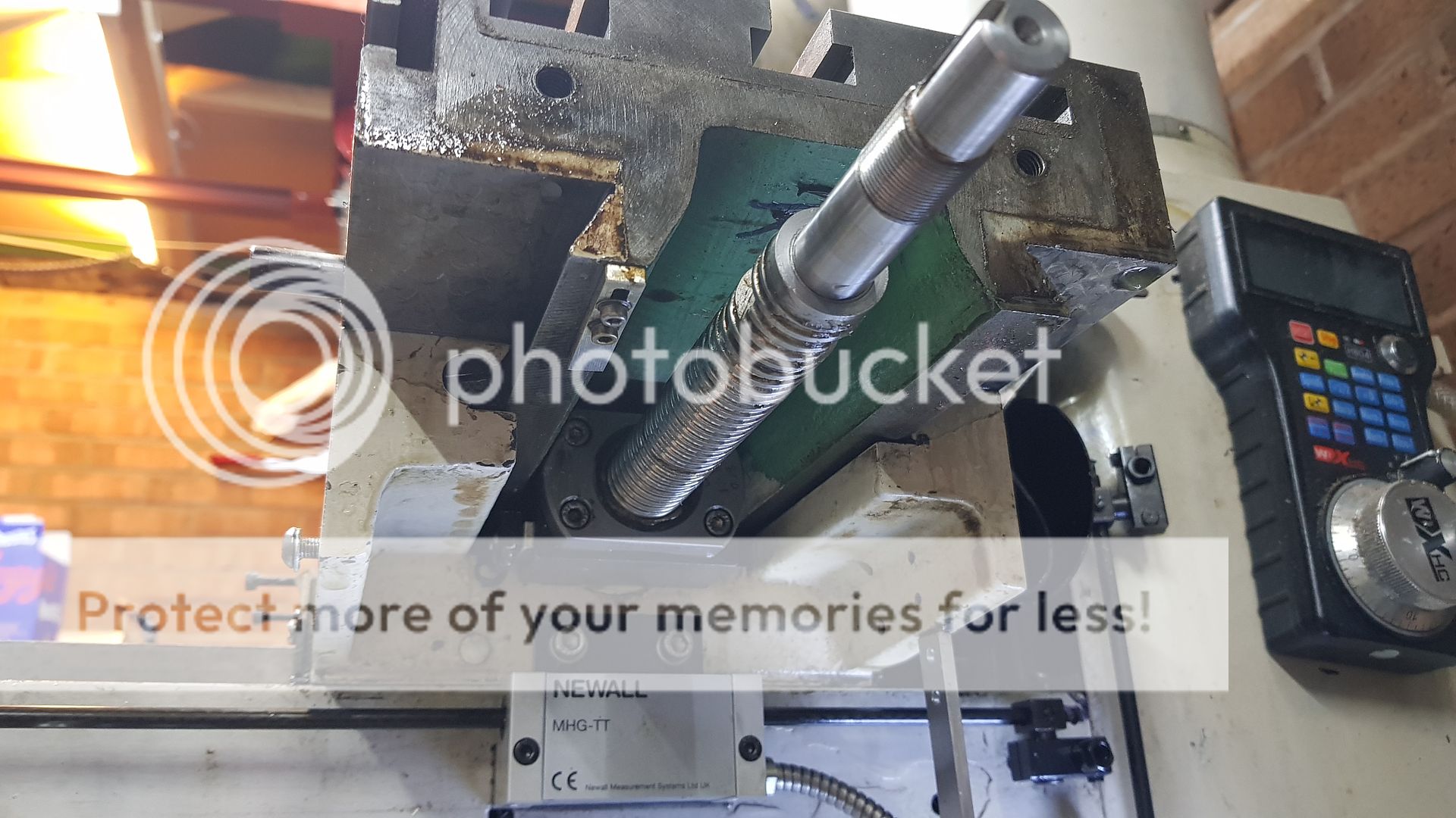 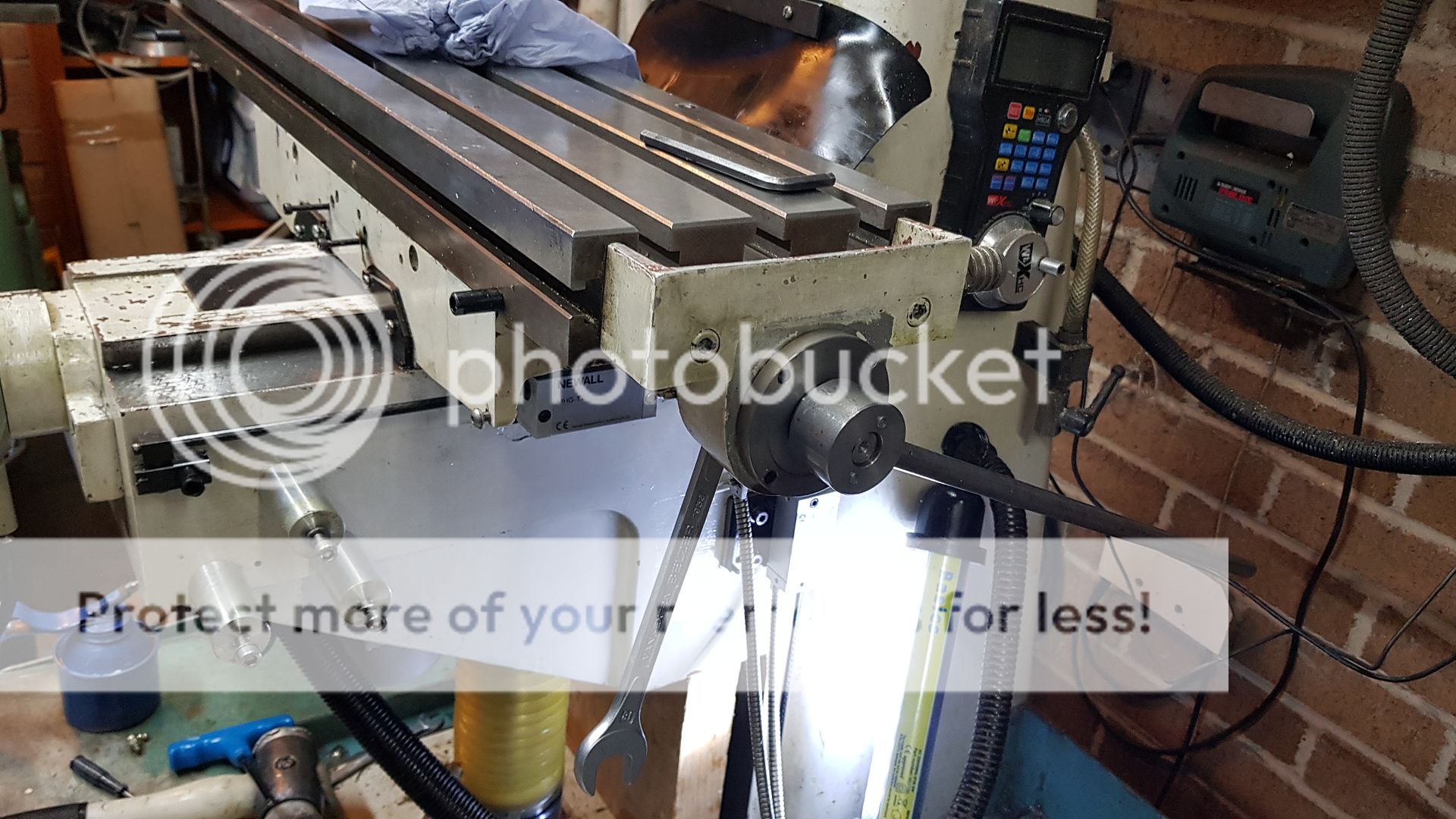 The machine uses a 24V Safety contactor that's actuated through the Emergency stop button. The contactor provides mains power to the Spindle frequency converter and the power side to the AC Servo amplifiers. This guarantees that it will stop if I hit the button. The contactor is closed when the Machine On button is pressed. 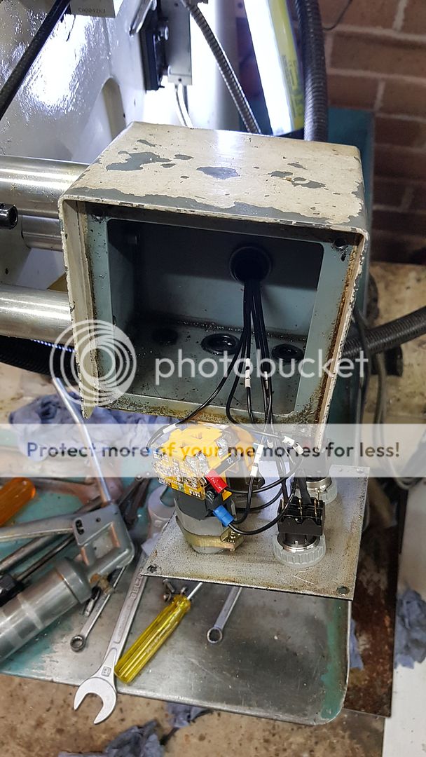 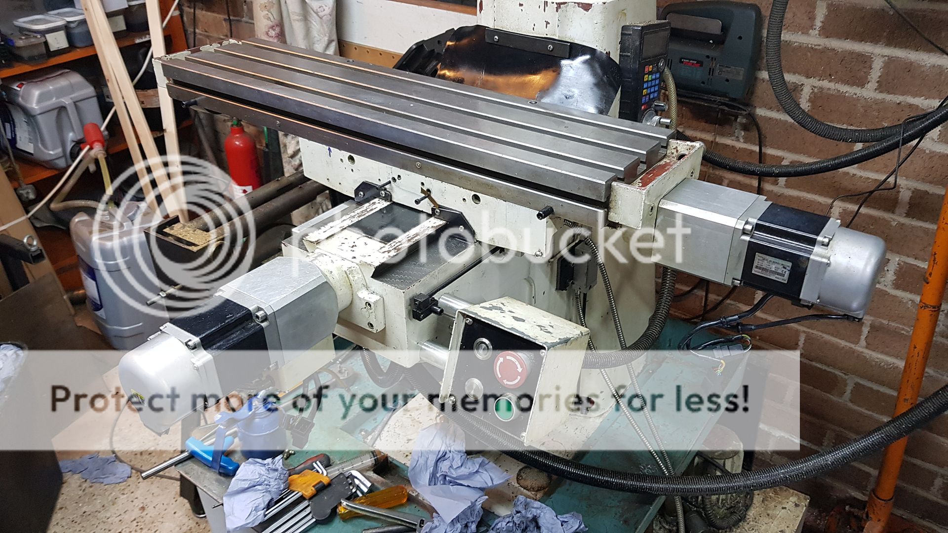 It's almost all back together now, just a few more hours and I can carefully run it from limit to limit and figure out the software limits and homing sequence that I haven't bothered with to date. The homing isn't that useful from the point of view of restarting a job, it won't repeat well enough with the microswitches. When I finally close the linear encoder loop, I'll arrange for the marker pulses to provide the homing references. |
|
timo
E-xcellent poster
   Completing 3 1/2 Rainhill .Building 5" Railmotor and waiting to start 3 1/2" King
Posts: 234
|
Post by timo on Aug 10, 2019 8:23:19 GMT
Roger,
You have certainly put a lot of effort into that conversion and it is really interesting to see what you have done.
I bet you will be glad to get the whole thing back together and into use!
Will going closed loop improve the accuracy much?
Tim
|
|
|
|
Post by Roger on Aug 10, 2019 9:02:07 GMT
Roger, You have certainly put a lot of effort into that conversion and it is really interesting to see what you have done. I bet you will be glad to get the whole thing back together and into use! Will going closed loop improve the accuracy much? Tim Hi Tim, It certainly took a while to research and figure out what I was going to do. There's so much opinion dressed up as fact on the CNC forums where I was trying to get some ideas on what best to do. In the end I ignored all the advice and did my own thing. I was being told that there was no point in going to better than 10micron resolution and that making the knee the Z-axis wouldn't work unless there was some sort of counterbalance. Both wrong. So often you're better off using your own judgement rather than sheepishly follow what everyone else is doing. I reckon there's about 10microns to be gained in accuracy in the X/Y axes and possibly more in the Z where it's difficult to guarantee what's going on. It's not a simple thing to do though, most control systems for the PC won't handle linear encoders. Basically what I want to do is to add a control box in between the SmoothStepper output from Mach4 and the AC Servos which are closed loop to the actual leadscrew position. I'd just be dealing with the backlash element really. Classical control systems aren't very good when you have things like backlash that can vary if the slides become stiff. Fuzzy logic is much better at dealing with these things because they are Rule based. If you haven't looked at anything like that, there's loads on YouTube. It's very interesting and is used widely these days in everything from Washing machines to automatic controls for Underground trains. |
|
timo
E-xcellent poster
   Completing 3 1/2 Rainhill .Building 5" Railmotor and waiting to start 3 1/2" King
Posts: 234
|
Post by timo on Aug 10, 2019 9:44:06 GMT
Dear Roger,
Interesting.
I wonder if using something similar to the bed levelling algorithms for 3D printers would work? You could possibly keep it digital with a Pic / Arduino in circuit doing the backlash compensation. You would also have to have a simple calibration system in place which might be as complex as the interface! How do the big Haas and similar beasties handle this? I did see a report on the big Swiss nmachine tool show where they were actually putting bluetooth and sensors in boring bars so that you could dynamically change feed rates etc to eliminate chatter. Mind boggling!
Best Regards
Tim
|
|
|
|
Post by Roger on Aug 10, 2019 10:43:26 GMT
Dear Roger, Interesting. I wonder if using something similar to the bed levelling algorithms for 3D printers would work? You could possibly keep it digital with a Pic / Arduino in circuit doing the backlash compensation. You would also have to have a simple calibration system in place which might be as complex as the interface! How do the big Haas and similar beasties handle this? I did see a report on the big Swiss nmachine tool show where they were actually putting bluetooth and sensors in boring bars so that you could dynamically change feed rates etc to eliminate chatter. Mind boggling! Best Regards Tim Hi Tim, I'm not sure what they use for bed levelling, but it's not really the same problem. My preference would be not to tell the system about backlash, but design it so that the logic is robust enough to deal with it. That's where Fuzzy Logic comes into its own because it's not using formulae it's using rules. The rules can be absolutely anything and in any proportion. They don't have to be related to each other, but the sum of the weightings of all of the rules contributes to the output. To get a handle on what this is all about you have to delve into it a bit, it's not like anything else you will have seen in control theory. There are tools that help you develop and simulate the system and these usually compile down to a program in 'C' which can be ported to whatever microcontroller you want to use. Pics are an obvious choice since I have the development kit for those, or if the computational requirements become too great, it's feasible to program a FPGA to do it in hardware. I'm not suggesting that's necessary for this application though, but there are challenges in creating the required Step and Direction pulses for the AC Servos if that's the route being followed. It might be easier to drive the SureServos from a +/-10V analog output which they are capable of handling. However, that doesn't then allow the position control loop in the SureServo system to work because you're not telling a position to go to any more. It's certainly not a trivial thing to figure out, but interesting nonetheless. A purely digital solution would be my preference, adding or subtracting pulses going to the SureServo based on where the table actually is. I imagine the big boys either have their own dedicated controller or they buy them in from someone like Fanuc, Siemens or Heidenhain. |
|
timo
E-xcellent poster
   Completing 3 1/2 Rainhill .Building 5" Railmotor and waiting to start 3 1/2" King
Posts: 234
|
Post by timo on Aug 10, 2019 12:18:03 GMT
Dear Roger,
All fascinating stuff!
The bed levelling for 3D printers is actually adjusting the Z axis for a non flat bed. It takes a number of samples across the bed (hall sensors or some such) - mine had 9 or so. It then makes a 3D profile of the bed and adjusts the Z axis steps depending upon what it is told from the levelling pass. It does ths levelling exercise before each print run. I bought a 3D printer a couple of years ago for a business project that didn't take off and then sold it 3 months ago to fund lathe tooling - a QCTP plus toolholders.
I will certainly read up on fuzzy logic again - came across it some while ago and it made perfect sense at the time! I do wonder about temperature compensation as well or do you have a constant temperature workshop? Does one get a constant temperture profile along the length of a feedscrew for instance? There are so many variables I guess you rapidly reach the point of diminishing return.
As far as the analog stuff, I suspect you would need a significant number of bits in the D/A and A/D. Reminds me of 'programming' an analogue computer in the dim and very distant past.
Best Regards
Tim
|
|
timo
E-xcellent poster
   Completing 3 1/2 Rainhill .Building 5" Railmotor and waiting to start 3 1/2" King
Posts: 234
|
Post by timo on Aug 10, 2019 14:03:20 GMT
Dear Roger,
Been pondering this a bit more.
I wonder whether the bigger issues are knowing the absolute position of the axes and digitaly measuring the backlash. To get down to sub 10 micron you will need to sense absolute position plus a relative movement within 1 micron. I guess that your scales are 1 micron but I can't think of a way of sensing a stop or a slip clamped to the table to this level of accuracy. I guess you could start at one end of the travel and then every cm or so step 1 forward and one back and see if the dro reads a change, if not then go to two steps each way etc. This would give you backlash within +- one step. I would think that at this level things like parallelism between the table and the scales, stiction from the oil on the ways etc are going to start having an effect.
Are you actually seeing a machining problem at the moment? I know all my errors seem to accumulate unidirectionally!
Best Regards
Tim
|
|
|
|
Post by Roger on Aug 10, 2019 15:03:59 GMT
Dear Roger, All fascinating stuff! The bed levelling for 3D printers is actually adjusting the Z axis for a non flat bed. It takes a number of samples across the bed (hall sensors or some such) - mine had 9 or so. It then makes a 3D profile of the bed and adjusts the Z axis steps depending upon what it is told from the levelling pass. It does ths levelling exercise before each print run. I bought a 3D printer a couple of years ago for a business project that didn't take off and then sold it 3 months ago to fund lathe tooling - a QCTP plus toolholders. I will certainly read up on fuzzy logic again - came across it some while ago and it made perfect sense at the time! I do wonder about temperature compensation as well or do you have a constant temperature workshop? Does one get a constant temperture profile along the length of a feedscrew for instance? There are so many variables I guess you rapidly reach the point of diminishing return. As far as the analog stuff, I suspect you would need a significant number of bits in the D/A and A/D. Reminds me of 'programming' an analogue computer in the dim and very distant past. Best Regards Tim Hi Tim, Yes, that's how I understand the bed levelling, but I don't think it's applicable to this issue. You can't really get involved with temperature compensation on this sort of machine in the home environment, even though it certainly does affect things. Without active temperature control of the machine body and that of the workshop too, you're never going to make a difference. We just have to accept that there will be errors due to temperature. Strangely enough, you only need about 12bits to control the velocity since it's the speed you're setting not the position. That's all I used on the CNC machine control that I designed for the PCB drill/router and it was plenty good enough even for the very dynamic control system on those. |
|
|
|
Post by Roger on Aug 10, 2019 15:14:03 GMT
Dear Roger, Been pondering this a bit more. I wonder whether the bigger issues are knowing the absolute position of the axes and digitaly measuring the backlash. To get down to sub 10 micron you will need to sense absolute position plus a relative movement within 1 micron. I guess that your scales are 1 micron but I can't think of a way of sensing a stop or a slip clamped to the table to this level of accuracy. I guess you could start at one end of the travel and then every cm or so step 1 forward and one back and see if the dro reads a change, if not then go to two steps each way etc. This would give you backlash within +- one step. I would think that at this level things like parallelism between the table and the scales, stiction from the oil on the ways etc are going to start having an effect. Are you actually seeing a machining problem at the moment? I know all my errors seem to accumulate unidirectionally! Best Regards Tim Hi Tim, I don't think you need to measure the backlash, just design a robust system for controlling the Servos to end up with the desired linear encoder reading that matches the target value. I designed my system with 1 micron resolution throughout, so I output positions to that and also measure to that on the encoders, both rotary and linear. If you try to use a measured backlash value, what do you do when that changes? The idea is to go the exact target position, else you're no better off than I am at the moment. I'm currently correcting for measured backlash values. I don't get any accumulated errors, the AC Servos are closed loop so they always go to the exact encoder position that matches the desired position. I just don't like controlling the leadscrew when it's the table position I want to control. There are some situations where the knee deviates slightly more or less than the measured backlash although it's not been a huge problem. It's just not ideal and I do like an ideal solution! |
|
|
|
Post by ettingtonliam on Aug 10, 2019 17:50:39 GMT
All way above my head I'm afraid, but very impressive anyway. I'm curious where you sourced the plastic bellows which protect the Z axis screw.
Its too late for me now, because I sold the machine a couple of years ago, but when I had a Centec 2B, there was a bellows protecting the Z axis screw on that, made from a series of leather discs with a hole in the middle, and sewn together at the edges to form the bellows. When I got it, a lot of the sewing thread was missing, but even when I sewed it back together again with strong thread, the leather itself was rotten, caused by years of contact with oil. I looked all over for suitable replacements but couldn't find anything. The closest would have been bellows from the front forks of a motorcycle, but I couldn't find any big enough.
|
|
|
|
Post by Roger on Aug 10, 2019 21:37:29 GMT
All way above my head I'm afraid, but very impressive anyway. I'm curious where you sourced the plastic bellows which protect the Z axis screw. Its too late for me now, because I sold the machine a couple of years ago, but when I had a Centec 2B, there was a bellows protecting the Z axis screw on that, made from a series of leather discs with a hole in the middle, and sewn together at the edges to form the bellows. When I got it, a lot of the sewing thread was missing, but even when I sewed it back together again with strong thread, the leather itself was rotten, caused by years of contact with oil. I looked all over for suitable replacements but couldn't find anything. The closest would have been bellows from the front forks of a motorcycle, but I couldn't find any big enough. I have those specially made for the machines that I support. They come from a company called Beakbane, and they cost me £111.00 each ex vat when I order 6 at a time! They are a welded construction and they last a decent amount of time but eventually after about ten years they start to go brittle. I've tried to find a source for these elsewhere, but I can't find one. |
|
|
|
Post by Roger on Aug 10, 2019 21:57:06 GMT
I've still got to attach the X-axis linear encoder and add the covering angles, but other than that, this is complete. Most of the day was spent in modifying the Mach4 default screenset so that the on screen Jog buttons work the way I want them to and to set up the limit and home switch definitions so I can home the machine from now on. I haven't bothered in the past, but I really ought to start doing this properly. Here's the machine in the homed position with the axes as far +ve as possible. I'll have to keep the base clean and tidy to prevent accidents where the knee gets very close to the base. You can see just how much daylight I've created on this little mill by adding the long neck! 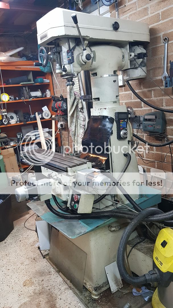 Having swung the head round, I thought I'd better tram the head to make sure it's at good as I can get it. There was about 80 microns difference between the two readings, but that's come down to about 6 now. This is the way I do it, just swinging the clock from one side to the other. 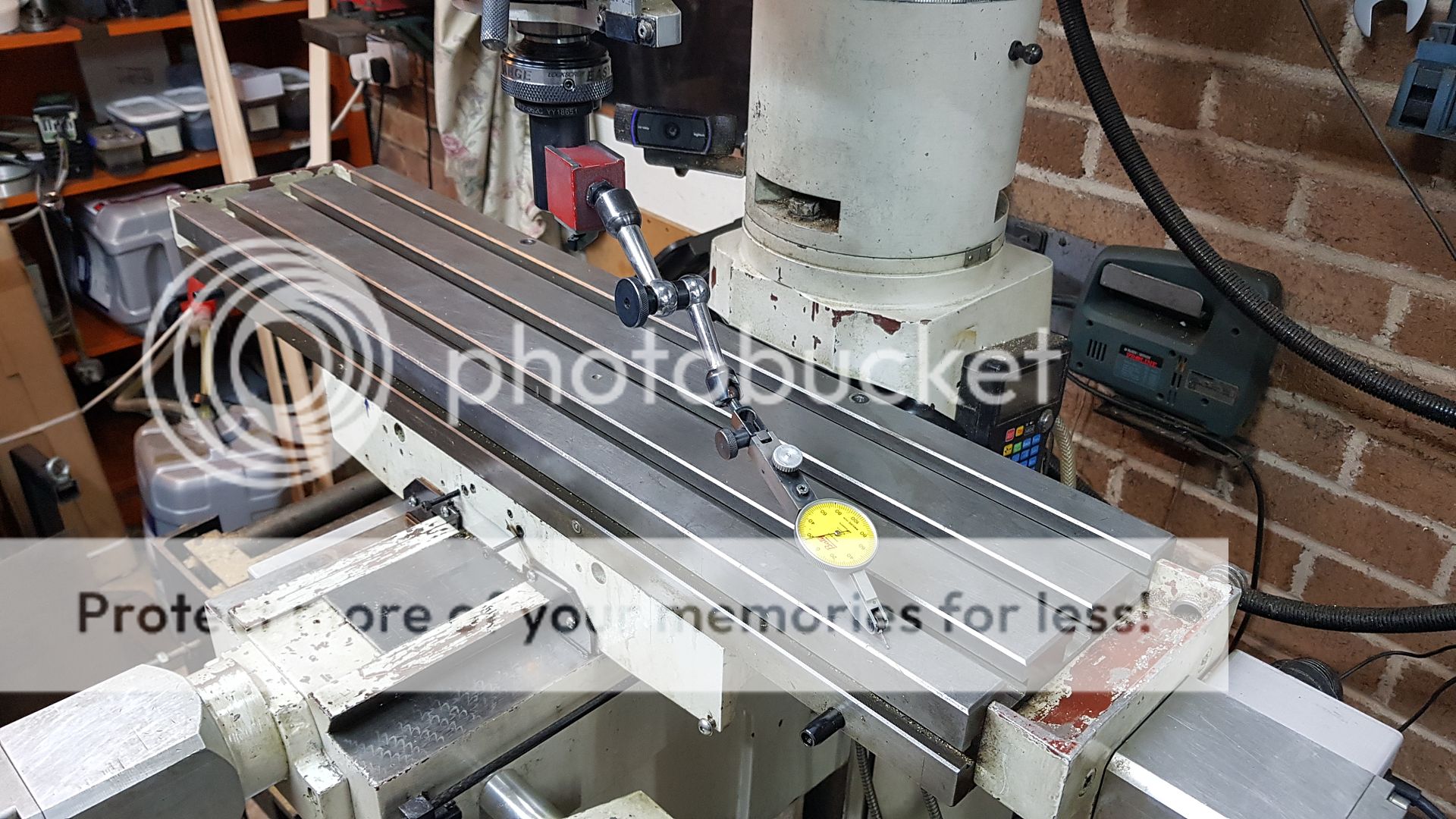 ] 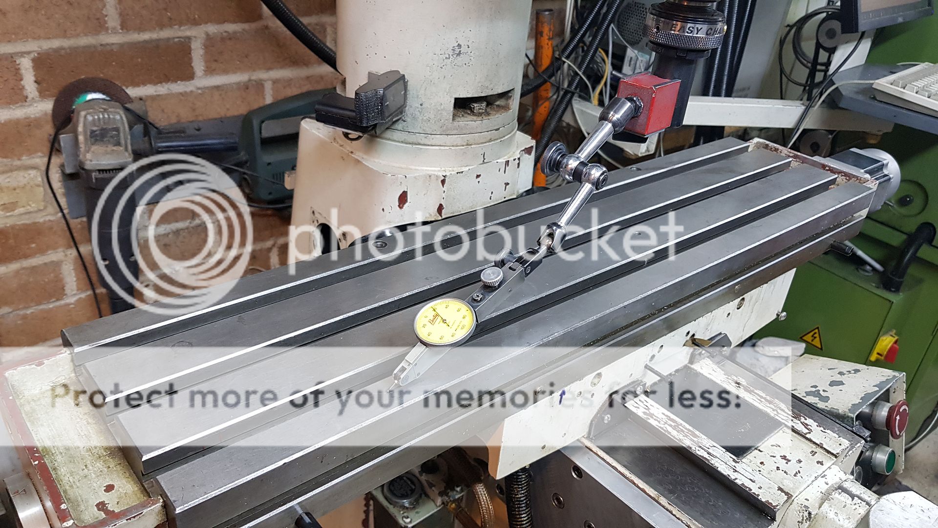 I slot a piece of material in between the belt guard and the top of the casting. Using a mallet isn't that satisfactory, it causes the clock to jump and upsets the measurement. It's far better to clock both sides and then gently lean on the bar to get it to move. This took all of five minutes to get this close. 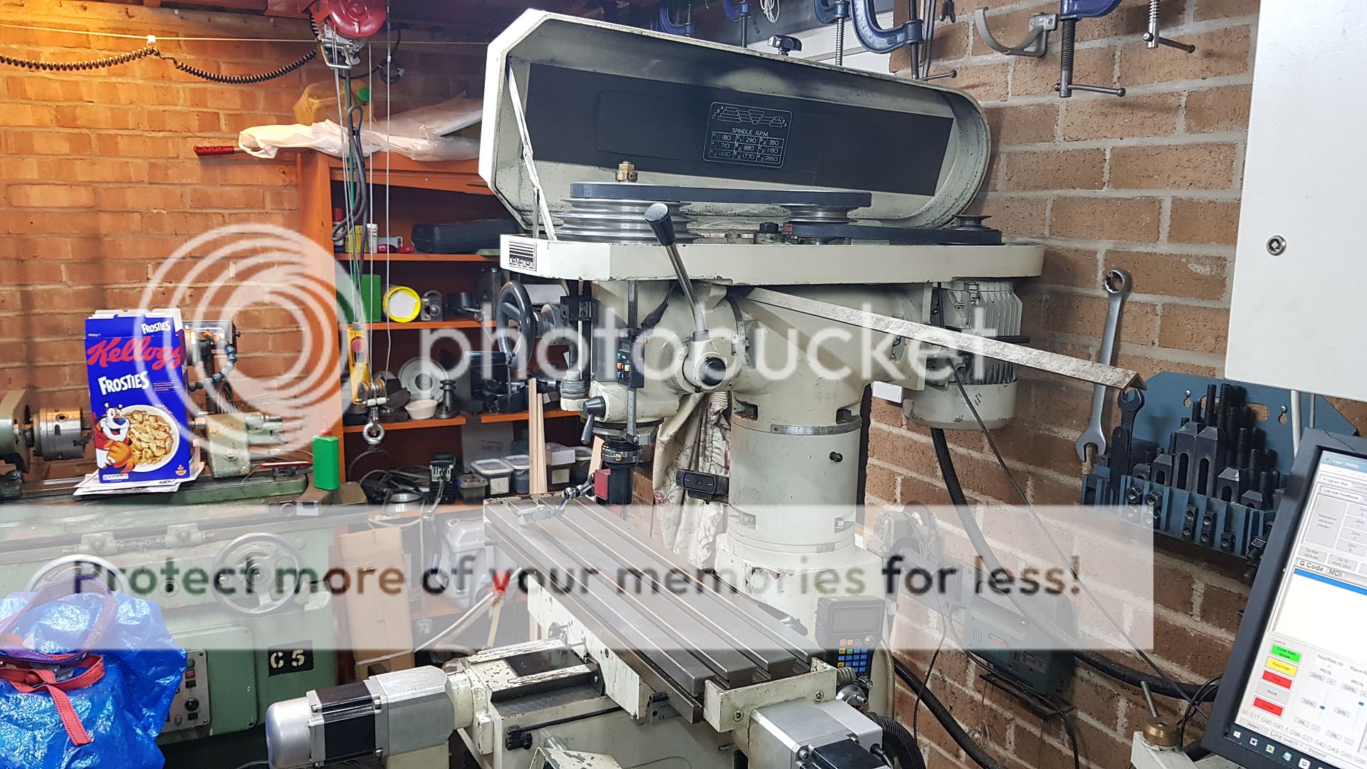
This is how the screen looks. It's basically the same as the default with a few essential changes to make it usable. The Jog tab didn't allow for easy changing of the jogging modes and steps in a clear and safe way. I've implemented specific buttons for each increment that I need, from 1mm to 0.001mm in steps of 10 microns. Most of the systems, including MPGs, seem to want to step through them. I just want to hit whatever I want, be it continuous or a specific increment in one click. The other unwelcome change on Mach4 is the MDI which forces you to press Cycle Start to execute it. That's because they've made it a multi line affair, so the return key is needed to throw a new line. Heaven knows why they changed it, it's a pain in the neck. It also doesn't delete the commands when they've been executed. What's worse is the fact that you hit the same Cycle Start button for the MDI AND the program which is frankly dangerous in my opinion. Needless to say, I've changed that! You can see that I've left the MDI tab next to the G-Code one, but I've also squeezed in a one line MDI that executes a single command from the keyboard when you hit enter, and clears the MDI for the next command, just like they had in Mach3. If it ain't broke, don't fix it! On the original MDI tab, I've added a dedicated Run button for that in case I need to use it. I guess it might be useful on occasion, but I haven't used it yet, and I've had the thing installed for months. Mach4 requires you to hit the Soft Limits On/Off button else when it's homed they don't work. Even their YouTube video on Soft limits and homing says it's a good idea to have that on by default, they even show you how to edit the homing script to make that happen. Quite why they don't just make it do that by default is beyond me. Anyway, enough moaning, it now works in the way I want it to, and the homing and soft limits are functional. Just a few bits to bolt back on and I can get back to doing something useful with it! 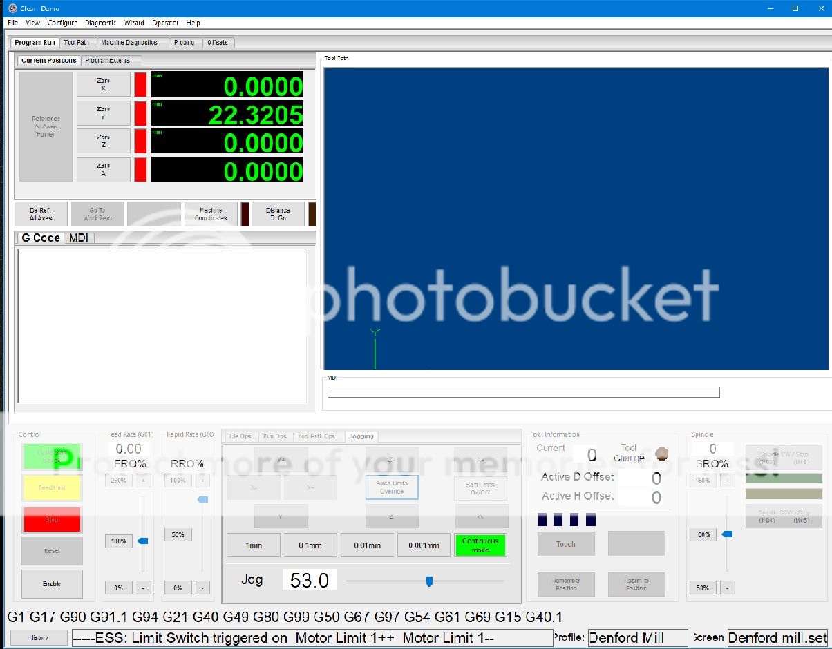 |
|


