|
|
Post by David on Dec 5, 2019 9:40:54 GMT
Sadly I don't have the answer to the subject, I'm asking for advice. I started a new thread rather than hide this in my CNC or B class build thread because other people might be interested. I have modeled the dome in F360 and done a toolpath to rough turn the part above the flare. The modeled dome. What is not modeled is the bore for the inner dome and a smaller bore that goes all the way though. These bores will be done on the manual lathe first and used to hold the stock on a mandrel for CNC turning and milling. I'll probably use a clamping washer on the 19mm flat at the 'top' of the dome when turning which is why that part isn't touched.  The result of the initial rough turning operation. This will be done with the RapidTurn.  I saved the result of the turning operation as a STL file and imported that as a body so I can use it as the starting stock for the milling operations. Obv in the hope that F360 will not try to machine the material already turned off.  I've just noticed the large amount of stock at the dome base - that isn't necessary due to it being held with the mandrel. When I did the initial turning toolpath I forgot this and put enough stock to hold in a chuck. So I'll shorten the stock to just include the lowest point of the base of the dome. So the questions: 1. Assuming I'm going to hold this on a rotary table / 4-jaw chuck (so I can flip it over and machine half at a time) would you have the top or the base of the dome at the chuck end? The top of the dome won't need any more machining, just smoothing with sandpaper when all the machining is done. I assume the toolpaths will be easier with the base hanging out, but that will be quite an overhang - about 90 or 100mm. 2. F360 users, what toolpath would you use to machine the flare? I've tried adaptive clearing but can't get much from it. It didn't even machine down to the halfway mark. I'm guessing it's all about the geometry tab but there's so many options and I don't know how to use any of them! 3. Would you use a boring bar to cut out the radius where it sits on the boiler or do that with milling cutters and a CNC toolpath? |
|
jasonb
Elder Statesman

Posts: 1,293
|
Post by jasonb on Dec 5, 2019 15:27:07 GMT
I think I would be inclined to stand it vertically eg as it will be on the loco and just do a 3D contour going down in shallow depths. If you use a corner radius cutter you will get minimal steps to clean up or if not bothered by time make each stepdown very shallow say 0.25mm. Does depend on how tall the part is as to what length tool you can use. This way you don't risk a joint line if thr 180 rotation to do the second side is not perfect
If doing it on it's side then I would have the part rotated 90degrees from how you have it and tool from above eg machine spindle in line with boiler that way you can use a larger diameter tool as it will fit into the larger diameter of the flared internal corner, this will mean the tighter internal radius where the round flares out to the top of the boiler will
The underside of the saddle could be done with a boring head set to swing the diameter of the diameter of the boiler which is probably the usual way of doing it and gives a very smooth finish. Could also be milled with teh side of the cutter against the curved underside again giving a good finish, you have plenty of room for a decent diameter cutter so length won't be an issue. or you could stand on end and with a ball nosed cutter do a series of parallel contour cuts, again the amount of your stepover will determine how smooth the finished face is.
F360 has the option to share the file, you could post the link here and we can try out some options.
|
|
|
|
Post by racinjason on Dec 5, 2019 21:26:03 GMT
David
Try the Flow tool
Jason.
|
|
|
|
Post by David on Dec 5, 2019 21:43:09 GMT
Thanks guys. It's about 90 - 100mm high so I don't think standing it upright is viable because the chuck and spindle will hit it. I'll turn it 90deg and try a flow tool. Here's the link for sharing if you're willing to have a look. a360.co/2YkbFgS |
|
|
|
Post by David on Dec 6, 2019 9:53:15 GMT
I couldn't get anything useful from the flow toolpath. It seems I'd had some luck back when I was mucking about with the chimney using the parallel toolpath. I've been trying to replicate this but no joy yet. One thing was to have the turning and milling ops in the same setup so the milling operations could be set to rest machining from the last operation. I was trying to emulate this with the stock body but it wasn't working for me. I have to set a different WCS for the milling ops but that's no problem.    |
|
|
|
Post by simplyloco on Dec 6, 2019 10:00:03 GMT
I couldn't get anything useful from the flow toolpath. It seems I'd had some luck back when I was mucking about with the chimney using the parallel toolpath. I've been trying to replicate this but no joy yet. One thing was to have the turning and milling ops in the same setup so the milling operations could be set to rest machining from the last operation. I was trying to emulate this with the stock body but it wasn't working for me. I have to set a different WCS for the milling ops but that's no problem. Talking of a different language...  |
|
jasonb
Elder Statesman
Posts: 1,293
|
Post by jasonb on Dec 6, 2019 13:37:47 GMT
I had a quick play as though the part had not had any turning done and just used an adaptive clearing cut with a 12mm cutter leaving 0.5mm followed by a 3D contour using a 10mm R1 cutter. Did not worry about work holding but that is easy enough to avoid if you add a slightly oversize cylinder to the end of the part to represent your arbor Link a360.co/2PjCuxDFor those that have not yet learnt the language maybe pictures are more your level  www.youtube.com/watch?v=lELKydm1nMg www.youtube.com/watch?v=lELKydm1nMg |
|
|
|
Post by simplyloco on Dec 6, 2019 14:20:37 GMT
On the day you were born I was running a 10 ton AEC machinery lorry in the BAOR. Please don't patronise me, even in jest... |
|
|
|
Post by David on Dec 6, 2019 21:53:54 GMT
Thanks Jason, very kind.
I'll tweak it to use what I have and see how I go. I have a long 12mm cutter that should reach half-way down.
|
|
jasonb
Elder Statesman
Posts: 1,293
|
Post by jasonb on Dec 7, 2019 7:12:40 GMT
The reach is one of the problems needing about 45mm of stickout to be safe. I did run it for a 25mm dia insert milling cutter that I recently got which has the reach and is plenty rigid enough but it just misses a couple of small areas of the flared out bottom, you probably have then with a 12mm or so fillet which is just a bit too tight. One other downside is that it is only 2 inserts so feed is less but you can compensate for that by running faster and taking a heavier cut due to rigidity.. On the plus side it does have a 0.8mm radius corner so can do the roughing and finishing.
BTW what is the material?
|
|
|
|
Post by David on Dec 7, 2019 20:21:37 GMT
I'm hoping to use cast iron. Easy to machine and cheaper than brass. I love cast iron.
Tormach's TTS can't hold anything bigger than a 12mm cutter although I assume you can put any R8 collet in the spindle and use it to hold other things. That would make length offsets a massive hassle compared to using TTS though. I checked my long 12mm EMs yesterday and they seem long enough although flex/chatter will probably be a problem.
I can see now why you suggested the orientation - it allows machining of the curved bottom.
I've taken your toolpaths and copied them into the first setup with the lathe turning ops and am making some progress. I'm seeing some of the milling ops cut into the turned finish and have to sort that out - it may be as simple as the 'don't touch surfaces' option but that may leave parts un-machined.
I have some 6mm ball ended EMs on the way so will try and program a 'finish' cut with them although I'll still leave material for filing or sanding because I'm not convinced of the join between the flare and the tapered sides, despite using tangent arcs for the loft-rails. It could be a rendering artifact but last time I thought that the part came off the machine exactly as shown on the screen!
While not sleeping this morning I remembered the RapidTurn has a primitive indexing system built onto the spindle which will save me transferring the work to a rotary table and will hopefully give a more positive location than the 'rest a chuck jaw on a parallel' method I was going to use. I think I'm going to need some tailstock type support though.
|
|
jasonb
Elder Statesman
Posts: 1,293
|
Post by jasonb on Dec 8, 2019 8:09:17 GMT
The 25mm insert cutter that I have has an R8 shank so can go into the spindle and has about 48mm length of shank beyond the tapered part so would reach far enough, it's the one on the right www.arceurotrade.co.uk/Catalogue/Cutting-Tools/Indexable-Carbide-End-Mills/90-Indexable-Carbide-End-Millsused with inserts that have a greater corner radius than the usual 0.8mm you could get a very smooth finish but the 0.8 will probably do then one tall can be used to rough and finish www.shop-apt.co.uk/carbide-inserts-for-machining-milling-carbon-alloy-steel-general-use/adkt-150532-rr-nk225-carbide-inserts-for-milling-cvd-coated-for-steel-apt.htmlThe main reason for turning the part sideways was so that a larger tool could be used, if you had it the other way round you would be limited to a 10mm dia tool to get into the corners, doing it this way you can use a larger tool which is a lot more rigid, being able to do the underside at the same setting is a bonus.   Your 6mm ball ended cutters will probably be too short to reach to the half way point and they are also going to be slow on the early cuts as you can't feed them very fast due to the middle of the cutter hardly having any cutting speed. This is why I prefer a cutter with a corner radius as you get a higher speed at the cutting edge so can feed accordingly. If you do have a form of indexing then the short cutter problem could be solved buy doing it in 4 goes rather than two as the tool would only need to go part way down the sides which would almost half the stick out. Probably need a second setup with the Z axis at 90degrees and a path to suit. |
|
|
|
Post by David on Dec 8, 2019 22:55:01 GMT
The current plan is to use the long 12mm EM to rough it out in two 180deg setups, then use four 90deg setups with the 6mm ball-nose EM to semi-finish.
I like the look of the insert tool you have! The problem is that I'd have to remove the automatic draw-bar air cylinder, unscrew the 3/4" R8 collet, etc to use it. Too much hassle for one cutter.
I'm sorely tempted to get the MT3 version for the manual mill but I don't use that for big jobs any more. Or perhaps I just haven't had any having gotten to the stage of the loco I'm at.
|
|
jasonb
Elder Statesman
Posts: 1,293
|
Post by jasonb on Dec 29, 2019 7:44:57 GMT
This video shows a 6mm 4-flute ball ended mill being used for the final contour at 0.33mm stepdown, did not take much in the way of filing to blend in the cuts, as it is going to be a "cast" surface there was no need to waste time doing lots of fine passes. Run at 5000rpm and 500mm/min feed. Not shown at the start but the 6mm 3-flute cutter ramped down to form the bore no problen without any pilot hole so would be happy to do tabs with it. www.youtube.com/watch?v=2N_M1hH0NTA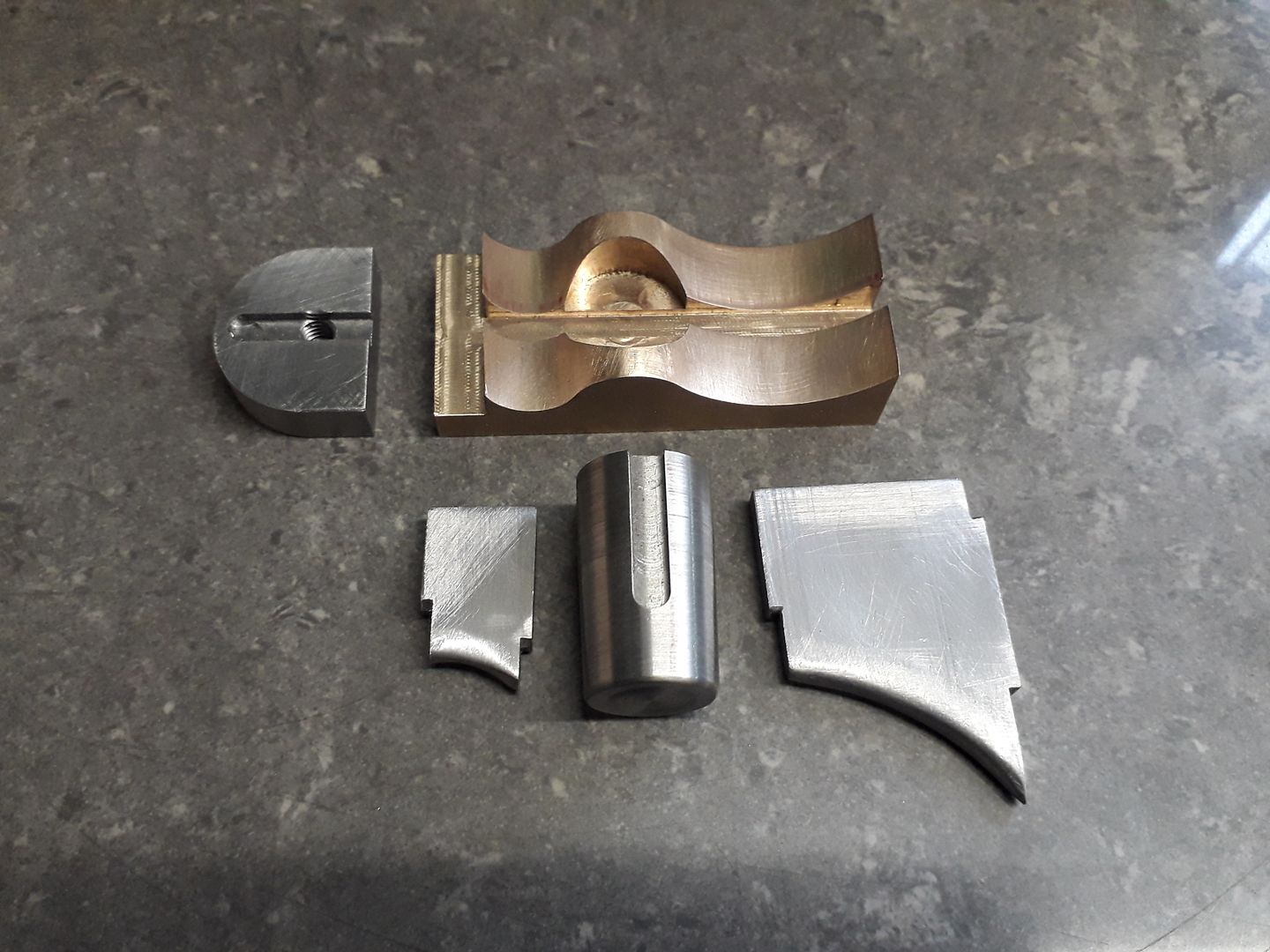 Also one from a couple of days forming a tee shape with a good fillet between the branches, 6mm cutter with 1mm radius corner for contour on that. www.youtube.com/watch?v=_Due-1nIHfE&t=5s |
|
|
|
Post by David on Dec 29, 2019 10:45:52 GMT
Very good. Is it brass or bronze? 5000rpm / 500mm/min is quite a bit more than I'd have tried but it clearly worked fine.
|
|
jasonb
Elder Statesman
Posts: 1,293
|
Post by jasonb on Dec 29, 2019 13:24:33 GMT
Bronze, 660 I think
|
|
|
|
Post by Roger on Feb 2, 2020 23:09:20 GMT
The current plan is to use the long 12mm EM to rough it out in two 180deg setups, then use four 90deg setups with the 6mm ball-nose EM to semi-finish. I like the look of the insert tool you have! The problem is that I'd have to remove the automatic draw-bar air cylinder, unscrew the 3/4" R8 collet, etc to use it. Too much hassle for one cutter. I'm sorely tempted to get the MT3 version for the manual mill but I don't use that for big jobs any more. Or perhaps I just haven't had any having gotten to the stage of the loco I'm at. The Indexable End mills are excellent, but I rarely use them because I find them to be excessively noisy. I've bought some polished inserts for Aluminium which work very well for Plastics too, but the General Purpose inserts are nowhere near as sharp as a solid end mill, and I think that's why they are so noisy by comparison. If you can run your machine without any noise limitations though, it would be a good choice and much cheaper than buying solid cutters of an equivalent size. |
|
|
|
Post by David on Feb 3, 2020 4:55:14 GMT
I have understanding neighbours and a well insulated workshop so noise isn't a problem. I love the polished alu inserts they give an effortlessly good finish on brass.
I don't really use the big cutters on the manual (or CNC) mill any more. Someones a shell mill for facing something off that seems too narrow for a fly cutter is about all. No side milling with anything over about 12mm.
|
|
|
|
Post by Roger on Feb 3, 2020 8:48:29 GMT
I have understanding neighbours and a well insulated workshop so noise isn't a problem. I love the polished alu inserts they give an effortlessly good finish on brass. I don't really use the big cutters on the manual (or CNC) mill any more. Someones a shell mill for facing something off that seems too narrow for a fly cutter is about all. No side milling with anything over about 12mm. You're very lucky with the noise then, I'm only using 'stealth machining', no chattering, no loud intermittent drumming cuts. I do all my machining in a way that you wouldn't know I was using the machine if you were stood 20 feet away. It takes a bit longer, but it's kind on the machine and on the cutters. A pedant would tell you that you're using completely the wrong insert for Brass, all the wrong angles and the edge being too easily chipped... but... what works is all that matters! |
|
|
|
Post by David on Feb 3, 2020 9:07:09 GMT
I have been very lucky with neighbours in the 14 years we've been here. Never had trouble with or from any of them. My machines aren't too intrusive from outside the new workshop unless I'm really hammering something with an interrupted cut etc. The compressor is probably the worst otherwise and it's just a murmur from outside (although a right clattering from the inside). A pedant would tell you that you're using completely the wrong insert for Brass, all the wrong angles and the edge being too easily chipped... but... what works is all that matters! I'm no machinist (obv) and don't even pretend to be one on YouTube, but I think the shiny Alu ones are "correct" for brass etc, given the info in the chart I downloaded. It has these letters on it which calls them ISO colour codes and it gives: P (blue) = Steel other than rustproof austenitic M (yellow) = Stainless & austenitic K (red) = Cast iron N (light blue on my packets, green on the chart) = Alu, non-ferris, non-metal S (orange on my packets, brown on the chart) = High temp alloys or other hard stuff eg nickel, cobalt, titanium alloys H (grey) = Hardened steel, hardened or chilled cast iron. N looks like the only one for brass etc. My steel ones are marked as cutting conditions "P" and my shiny alu ones are marked cutting conditions "N". |
|


