kipford
Statesman
 Building a Don Young 5" Gauge Aspinall Class 27
Posts: 566 
|
Post by kipford on Jun 11, 2020 12:22:47 GMT
I am preparing to make the valve gear and generally just checking things out. My 3D model reflects the nominal dimensions. All the valve gear parts have been laser cut, some are from Model Engineers Laser some are of my own design and came from work. Something Roger mentioned the other day made me think about the actual material thickness of the parts and what are acceptable side clearances. Typical is the radius rod/Vibrating link/jack link joints for the Joy valve gear. The picture below shows the parts. The radius rod is designed at 10 mm. The actual material thickness is 9.83 mm, hence giving a clearance of 0.17mm or 7 thou in old money. I reckon this is a little on the slack side. What is normally considered an acceptable value for side clearance in valve gear on a 5" gauge loco? I can adjust the gaps in the parts but in this case there is a knock on effect right down to the connecting rod and I have a concern with losing section width and the consequential reduction in stiffness on what are fairly highly loaded parts. Dave  Valve Clearance Valve Clearance by Dave Smith, on Flickr |
|
jma1009
Elder Statesman

Posts: 5,901
|
Post by jma1009 on Jun 11, 2020 22:33:27 GMT
Hi Dave,
(Proviso, never having made a Joy valve gear loco), I would say your top 2 red lines should have a side clearance of 2 thou either side, and similar with the bottom red line pin joint.
I agree you don't want too much side play on these bits, but don't be too precious and overthink all this... the Joy valve gear Minx and Maid of Kent (by LBSC in 5"g) runs very well even when well worn.
Don't forget that the driving axle tips on our uneven miniature tracks (some are a lot better tracks than others) and the bearings with the connecting rods with the valve gear links may need to be eased after valve setting with everything set at running height, and with no allowance for it moving and tipping and going up and down. And different bits of Joy valve gear may require different clearances.
Having had 2 of Don Young's locos in my workshop some 23 years ago, I can assure you that Don Young's own locos were quite roughly built.
It would be interesting to run the Joy valve gear 'Minx' and 'Maid of Kent' of LBSC, and Don's 'Aspinall' on a computer simulator; but this is way beyond my own capabilities with valve gear simulators!
Cheers,
Julian
|
|
|
|
Post by suctionhose on Jun 12, 2020 7:51:13 GMT
Typically, I make all the motion neat with no deliberate clearances for a start. This really helps with alignments. If it goes together like that you know things are properly aligned. It's ususl to straighten rods after machining. That's the fitter's job!
After it's all made and successfully assembled, I take it apart for finishing touches, polish etc. Then, on final assembly, ensure the running clearances and lubrication points are right.
|
|
kipford
Statesman
Building a Don Young 5" Gauge Aspinall Class 27
Posts: 566
|
Post by kipford on Jun 12, 2020 8:29:03 GMT
Thanks gents. I have managed to rework the parts to new nominals without any significant reduction in material section. I will build it as near to nominal as I can then. ease as required on assy. Julian I assume Don got the valve events somewhere near correct as an Aspinall won IMLEC a few years ago.
|
|
jma1009
Elder Statesman
Posts: 5,901
|
Post by jma1009 on Jun 12, 2020 22:15:59 GMT
Hi Dave,
I don't recall a Don Young 5"g 'Apinall' 0-6-0 winning IMLEC, but I do recall the late Arthur Morris of East Cowes building one and winning a gold or silver medal at the London ME exhibition. Norman Lowe had a lot of input into Don's design, and Don was tickled pink when Arthur's example won a medal.
Arthur's example was lovely and was displayed at quite a few of the IWMES exhibitions. Arthur never steamed it up or ran it on a track; and the boiler tests were shrouded in mystery, as I discovered when I went through all the IWMES archived boiler test records! The boiler had a hydraulic test which it passed but with the boiler finished and in the frames and with the loco complete and painted. To get a gold or silver medal the loco had to be in steam and I gather propane was used for the steam test of the boiler with the grate and ashpan removed.
I've never seen one of Don Young's 5"g 'Aspinalls' in steam on a track and performing.
I would certainly wish to run Don's design on a valve gear computer simulator before I made one - not that I have any intention of doing so.
As Don Young did not understand Stephensons valve gear, and all his loco link examples are faulty in this regard, I would suggest you check out the Joy valve gear.
Cheers,
Julian
|
|
|
|
Post by ettingtonliam on Jun 13, 2020 2:08:52 GMT
Is it a requirement of the ME Exhibition that a gold or silver medal winning loco shall be in steam? It certainly isn't a requirement for traction engines!
|
|
mbrown
Elder Statesman
Posts: 1,719
|
Post by mbrown on Jun 13, 2020 8:35:58 GMT
No such requirement when my model of LYN won a Silver medal at the 1990 ME Exhibition at Ally Pally....
I think the Curly Bowl was the first national competition class when performance in steam was a requirement. In the early days, of course, that was done during the exhibition itself on the SMEE track.
Hope that snippet helps.
Malcolm
|
|
kipford
Statesman
Building a Don Young 5" Gauge Aspinall Class 27
Posts: 566
|
Post by kipford on Jun 13, 2020 9:59:45 GMT
Julian There are a number of Aspinalls running I have photos of others. Les Pritchard built an Aspinall and won IMLEC with it in 2006, see extracts from ME below. So it must work to a degree! Dave 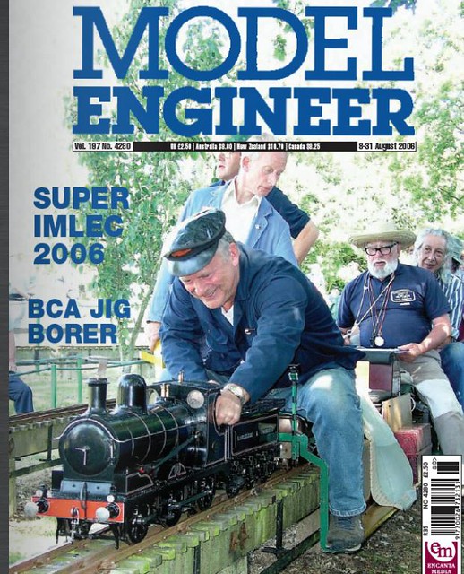 Capture ME1 Capture ME1 by Dave Smith, on Flickr  Capture ME2 Capture ME2 by Dave Smith, on Flickr |
|
|
|
Post by coniston on Jun 13, 2020 19:03:31 GMT
Nice Dave, some familiar faces and a familiar track to boot, albeit running opposite way to normal.
Chris D
|
|
jma1009
Elder Statesman
Posts: 5,901
|
Post by jma1009 on Jun 13, 2020 21:50:43 GMT
I am quite happy to be corrected on all this, and apologies due, as I had no recollection of Les Pritchard's example.
I do however have some recollection that to get a Gold or Silver medal at an ME exhibition ie the Model Engineer magazine Exhibition you would get extra marks if the exhibit was a working exhibit, and in some way, could be albeit tenuously proved.
Cheers,
Julian
|
|
|
|
Post by ettingtonliam on Jun 14, 2020 2:49:10 GMT
I'm not sure about that Julian, having only once exhibited at the ME exhibition, and that in 1973. I suppose in my case at least, the prescence of soot in the chimney might be held to be 'evidence' How that worked in the case of Cherry Hinds who for years was a multiple Gold Medal winner with her exquisite models of steam road vehicles, I don't know, because she never steamed any of them.
|
|
mbrown
Elder Statesman
Posts: 1,719
|
Post by mbrown on Jun 14, 2020 17:05:37 GMT
I know some controversies can run and run.... but in case it helps, I have just dug out my leaflet "Competitors' Information" for the 59th ME Exhibition (1990 or 1991). It has a lengthy essay about what the judges will be looking for. There is a lot about fidelity to prototype, correct choice of materials etc. - there is nothing about whether a model has to be a working one, but reading between the lines, one can detect some assumptions. For instance, under "suitability of materials" it says: "Copper boilers are obviously considered suitable even though the prototype would have undoubtedly been steel".
I think "ettingtonliam"'s comment on Cherry Hinds's models suggests that both working and non-working models are acceptable and that the judges will adjust their marking accordingly. To pick another example close to Julian's heart, I am not sure if Bradbury-Winter's "Como" was ever exhibited, but it surely would never have been disqualified for being true to scale in every respect and therefore not practicably steam-able.
Malcolm
|
|
|
|
Post by ettingtonliam on Jun 14, 2020 21:52:25 GMT
Malcolm
I'm not saying that Cherry Hinds models were non-working, I believe that they did work, on air, its just that as far as I am aware, she didn't steam them. For one thing, the scale she usually worked in was 3/4" to the foot. I know there have been working steam traction engines in that scale, but they are not easy!
I don't know what she did about boilers, whether they were built as a scale copy, or had workable internals. Her later engines were often taken from patent drawings, sometimes of engines which never existed, so I don't know how 'workable' they were.
|
|
kipford
Statesman
Building a Don Young 5" Gauge Aspinall Class 27
Posts: 566
|
Post by kipford on Jun 17, 2020 19:08:07 GMT
Continuing the valve gear theme. Pinning the valve gear? I reckon there are four options. Interference fit pin, Loctite, taper pins or roll pins. Don suggests either interference or taper pins on the draweing. The cross heads and coupling rods will be taper pins, but the decision now is for the Joy parts of the gear. On the drawings Don suggests that either interference fit or taper pins are used. But I note in the build manual for his later Standard Class 2 he has changed his mind to roll pins. I like the idea of either loctite or roll pins, what does everyone else think?
Dave
|
|
mbrown
Elder Statesman
Posts: 1,719
|
Post by mbrown on Jun 17, 2020 20:54:30 GMT
One advantage of a taper pin is that you just have to tap the small end and it comes free. A roll pin needs to be driven out for its whole length which means a suitable sized drift and (perhaps as important) good access for the drift and hammer. I use 1/16" taper pins for quite a lot of applications, like fitting handles onto shafts and other things which need dismantling fairly often, and they are easy to use. They hold the thing tight but come out easily too. I also use roll pins but for applications intended to be permanent but needing to be dismantled in extraordinary circumstances.
The only slight drawback is that, especially if the taper pin is quite short, you have to look very closely to see which is the small end. I have spent some embarrassing moments trying to get the big end through the small end of the hole....
Malcolm
|
|
don9f
Statesman
Les Warnett 9F, Martin Evans “Jinty”, a part built “Austin 7” and now a part built Springbok B1.
Posts: 960
|
Post by don9f on Jun 17, 2020 21:05:09 GMT
On the Austin 7 I’m currently working on (see separate thread), the valvegear pins are captive in one part with a grub screw into a “dimple” and free to rotate in bushes in the other part of a joint. There is room to do this on this model, but on others I have with less room, the pins have a press fit, instead of the grubscrew idea.
I’m sure roll pins or taper pins would be a good alternative if you have room, or could get them small enough....
Cheers Don
|
|
kipford
Statesman
Building a Don Young 5" Gauge Aspinall Class 27
Posts: 566
|
Post by kipford on Jun 18, 2020 6:58:05 GMT
Malcolm
I take your point about the taper pins and will probably go down that route for most of it. It may not be possible in one part of the vibrating link, where it has had to be thinned down. I think a revisit of the CAD model is required to review the options again.
Dave
|
|
nonort
Part of the e-furniture
If all the worlds a Stage someone's nicked the Horses
Posts: 277
|
Post by nonort on Jun 18, 2020 8:00:01 GMT
Don't use roll pins use proper spiral lock pins if you must. they are easier to remove. In my last joy geared engine I used a method which needs nether loctite or pins? I made the pins dead length and put a small centre drill hole in each end. when assembling the gear you place the assembled parts on a very solid base and centre punch the ends in the centre holes in the pins. I have never had one fall out yet in a couple of cases I used a tubular pin and made a G cramp arrangement to squeeze/expand the ends. To remove the pins if ever necessary drifting the pins out or pressing them out with the G cramp modified with a new anvil will do it with out destroying the gear. I think you can assemble the whole of the gear into the engine by fitting the small end and big end then attaching the anchor link as a unit. Best of luck.
|
|
kipford
Statesman
Building a Don Young 5" Gauge Aspinall Class 27
Posts: 566
|
Post by kipford on Jun 18, 2020 9:46:52 GMT
Thanks for that, I should have thought of it myself, but that's why we ask questions  . Looks like I have sufficient solutions to for all the areas of concern. Dave |
|
|
|
Post by suctionhose on Jun 20, 2020 23:28:38 GMT
With regard to valve events of this design, I recall a 3.5" Joy VG 0-6-0 owned for a while by a friend. That engine ran beautifully right back to mid gear. Having said that, being 3.5"g it probably has no relationship to the design you're building.
It occurred to me though with the sofistication of your CAD model, perhaps you can view the valve events as they happen during the rotation? (I've gone off simulators - too hard to configure correctly with confidence. Just draw it out...)
|
|


 . Looks like I have sufficient solutions to for all the areas of concern.