jasonb
Elder Statesman
  
Posts: 1,237
|
Post by jasonb on Jul 27, 2020 15:52:20 GMT
As this section seems to be a bit dead I'll post what I have been upto.
Not really sure if this should have gone into the 3D printing topic as it started with Graham Corry of Alyn Foundry fame asking on another forum if 3D printing would produce usable patterns, not much feedback but I said that I would be happy to do the drawings for him so at least he would have some files to print from. One problem with getting anyone to do it at a reasonable price was the fact the flywheel would need a 400mm x 400mm print area and the other bits were quite bulky too so prices coming back from commercial printers were high.
So I thought I would have a go at cutting the patterns on my CNC starting with the smallest which was a bearing cap approx 80x25x35mm high.
Then the "Yoke" which sits on teh top of a column and has a beam supported between the two bearings much like a beam steam engine, there is a core print as part of the pattern that will form the "U" shape when cast
Still waiting to hear in a CNC cut foam pattern for the flywheel will come in at an affordable cost, if not I may need to make a few more of these.
|
|
|
|
Post by jcsteam on Jul 28, 2020 8:32:06 GMT
Interesting Jason, what wood is it you've used? Pine?
Pattern making and casting are something I've always wanted to have a go at, I just have never got myself set up to do so.
|
|
jasonb
Elder Statesman
  
Posts: 1,237
|
Post by jasonb on Jul 28, 2020 10:33:23 GMT
The bearing cap and spoke are beech and the other items maple, mice dense hardwoods.
|
|
jasonb
Elder Statesman
  
Posts: 1,237
|
Post by jasonb on Sept 3, 2020 13:28:39 GMT
Just to conclude the pattern making session I thought I would add a couple of posts of the finished flywheel pattern. The almost 400mm dia rim was too big to turn so I did it on the mill, the "s" shaped curve on the inner edge was cut using co-ordinates from Alibre . This is where a DRO on the Z is handy as often the step is very small and hard to do with handwheel graduations. 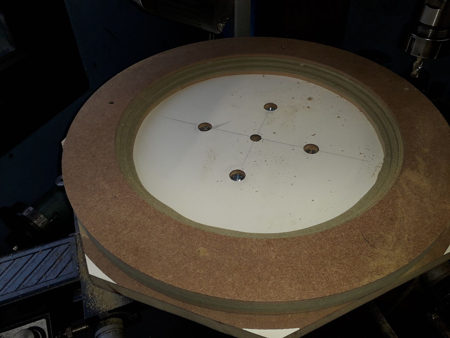 The spokes were then built into the rim and a disc of 6mm MRMDF added to the hub to both bring it upto thickness as well as add some strength to the spoke joints. The 2deg draft angle was cut by packing one side of the rotary table, same method for outside of the rim. 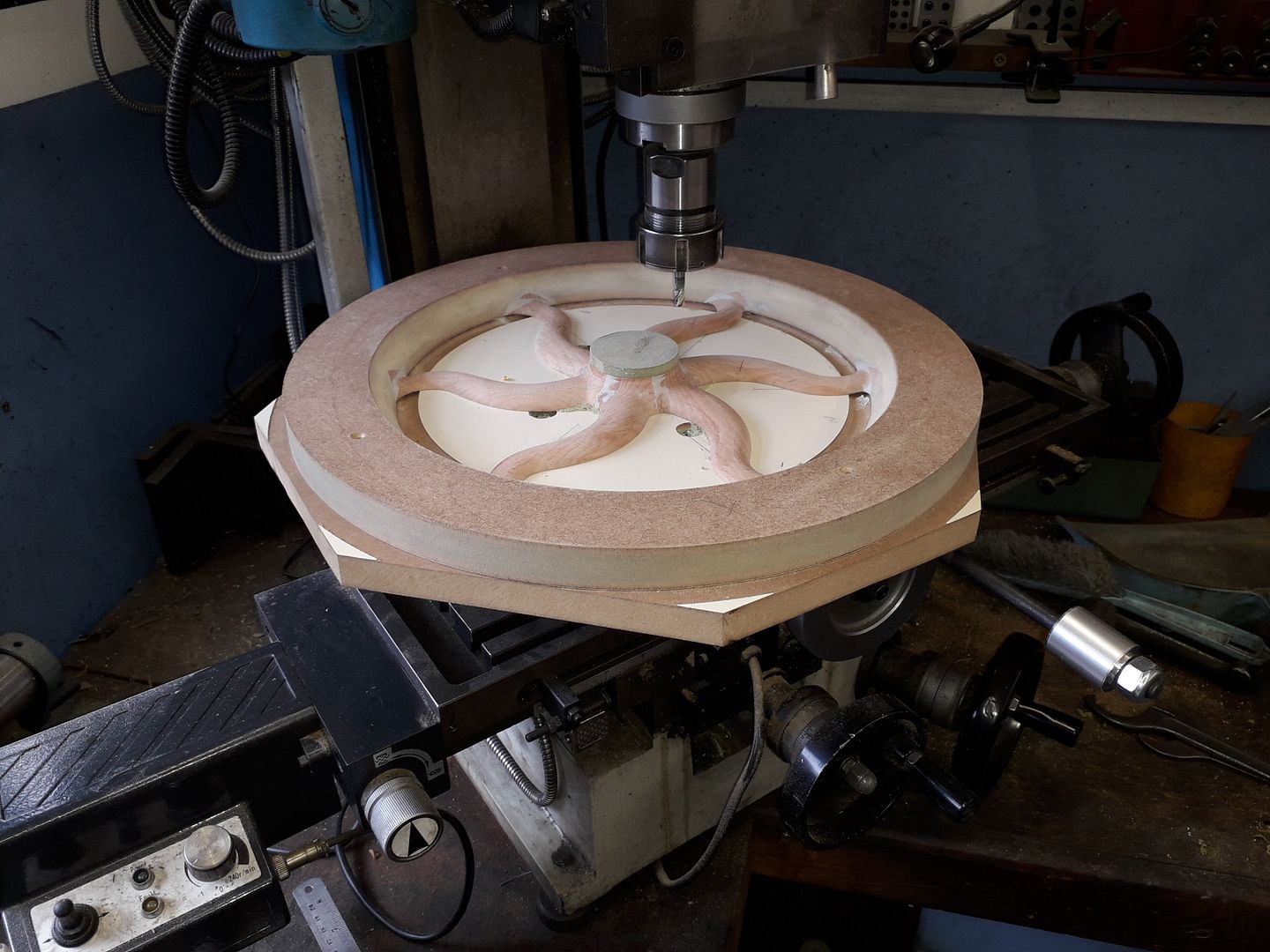 After a bit of filler and sanding it was done 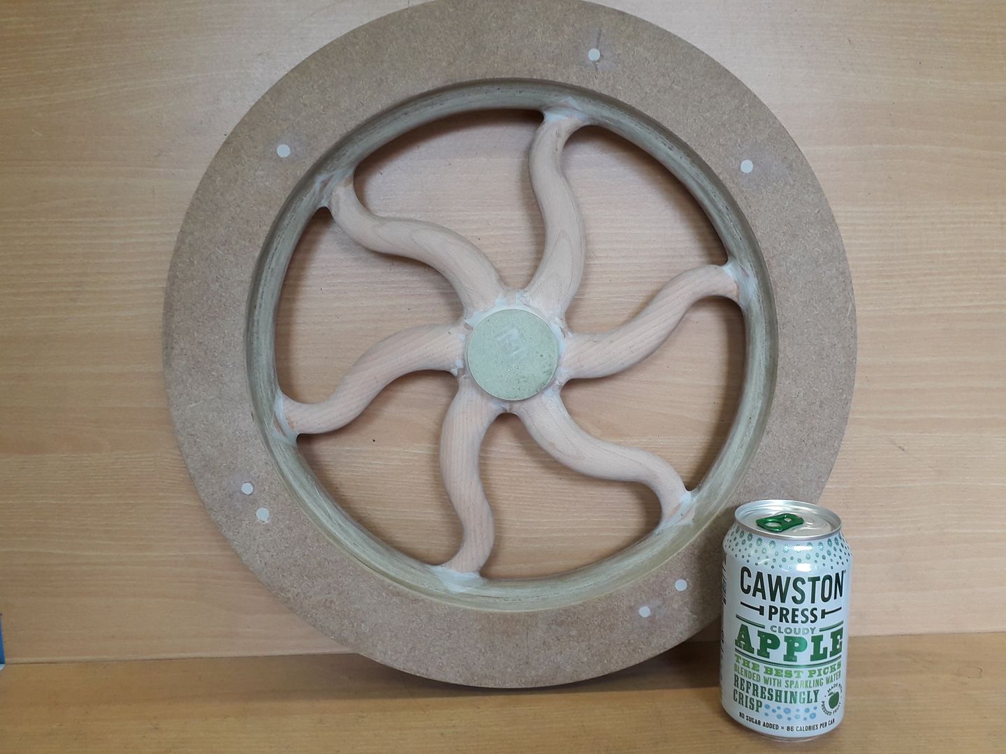 All the patterns together 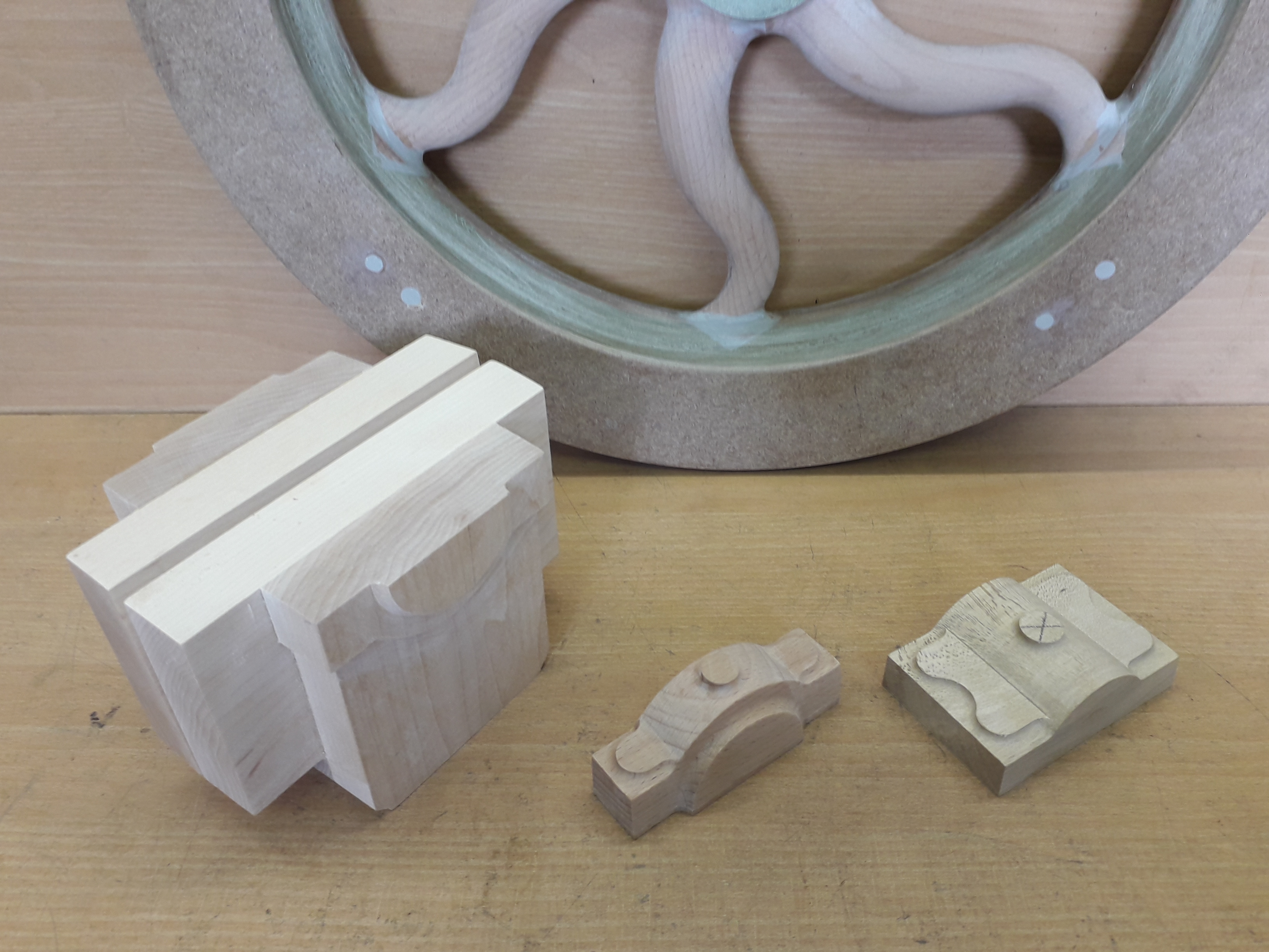 I also found time to make a rack for the ER16 collets I tend to use on the CNC, first try at engraving which turned out rather good. 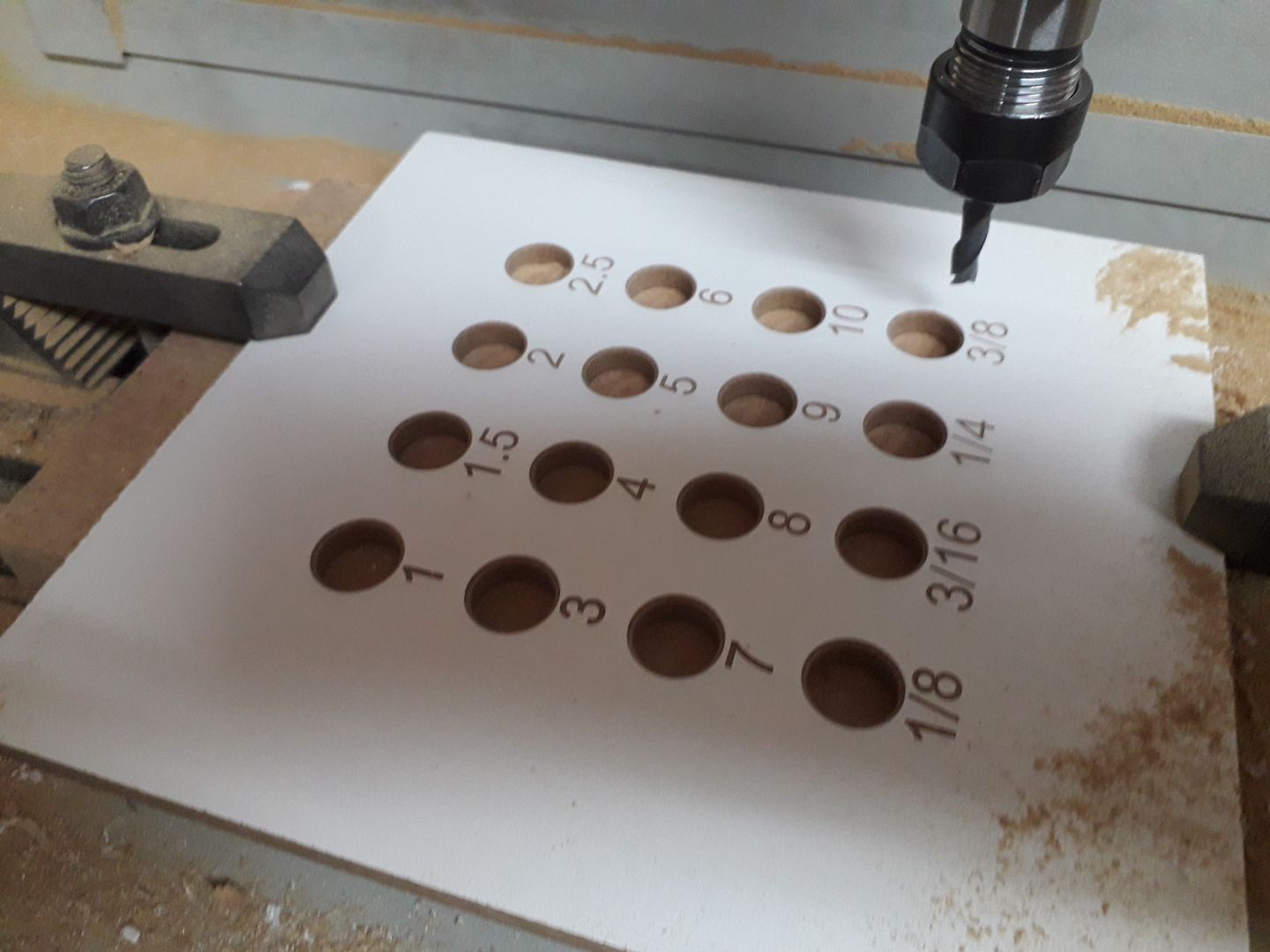 |
|
dscott
Elder Statesman
  
Posts: 2,440
|
Post by dscott on Sept 4, 2020 0:35:20 GMT
Lovely work Jason.
So interesting that to get round a big problem they come up with such lovely spokes to solve.
CONTRACTION AND CRACKING!
The most interesting Pattern I had to help with got made and poured for FREE by a foundry in Chudleigh in Devon.
They got to keep one for their gallery on the wall.
I had to advise the best way of making with the release angle upon the hairs. Alginate as used by dentists.
Scoop up in hand and press in place!!!!!
I had to choose BEST OF 3 GOES.
SHE THE STUDENT WAS 19.
Guess what it was?
David.
|
|
jasonb
Elder Statesman
  
Posts: 1,237
|
Post by jasonb on Sept 4, 2020 6:37:47 GMT
Sounds like a bit of body casting to me  Yes the curved spokes are supposed to stop the cooling flywheel destroying itself and do offer visual interest, I'm interested to see how it machines as the narrow part of the spoke is quite thin so will need careful support when fixing to a faceplate but I don't have that to worry about or the cost of casting! What I meant to mention about the engraving on the collet rack is that I particularly liked the way that the Vee pointed tool was ramped up at the ends of the letters to give a "square" end rather than the usual half round that a cutter leaves when running a simple 2D path. This leaves a nice valley at the bottom and mitres up into each corner. You can see it here on teh screen simulation And being cut, I mucked up the engraving first time around by also entering the 5000rpm in teh feed box so had the tool moving at 5meter/min! so ended up engraving and chamfering the holes then mill boring the holes afterwards but all came out OK in the end. |
|
|
|
Post by ettingtonliam on Sept 7, 2020 13:26:43 GMT
I made the flywheel pattern for my Stuart 600 gas engine flywheel (14" dia) in a similar way, building up from layers of MDF, but forming the curved spokes using a hand held router, following pencil lines. Quite nerve wracking.
The draft angle was done by packing the base plate of the router to the appropriate angle, and using the radius attachment.
I did quite a bit of 'traditional' pattern making at one time.
|
|