|
|
Post by Roger on Nov 24, 2020 9:05:57 GMT
Hi Michael,
There's a sticky post about hosting and including images in your posts, that's the best place to start.
I think you will need lateral clearance in some of the driven axles to accommodate tight radii. On my 0-6-0 tank locomotive, the middle set have very little clearance while the others have about 1.6mm from memory. I would be surprised if they all have large clearances on a Black Five, else the locomotive could slide from side to side by that amount. Others will know more about this than me though.
|
|
oldnorton
Statesman
 5" gauge LMS enthusiast
Posts: 693
|
Post by oldnorton on Nov 24, 2020 20:22:23 GMT
I still don't know how to post pictures. Attachemnts are not possible and a link to google photos seams not to work eighter...
Sorry about my suggestion to change the posting title, as that has left you in this new member folder. You really need to be in general and perhaps might have to start again This thread has more up to date photo tips, especially at the end linking-pictures-step-guide
|
|
oldnorton
Statesman
5" gauge LMS enthusiast
Posts: 693
|
Post by oldnorton on Nov 24, 2020 20:26:20 GMT
Another thing I discovered is that the driving wheels have nearly 2mm lateral play. I wonder if this is intended? Maybe to drive along short radius curves? The full size ones had play, and more on the centre axle. I cannot remember offhand what I put on mine, following Don Youngs view, I will look again if no-one has answered before me in a few days. |
|
|
|
Post by runner42 on Nov 24, 2020 23:02:09 GMT
Another thing I discovered is that the driving wheels have nearly 2mm lateral play. I wonder if this is intended? Maybe to drive along short radius curves?
Are you measuring the 2 mm between the hornblocks and wheels and not the mainframes and wheels? Don Young Black 5 has a 0.020" clearance between the hornblocks and wheels. Remember DY scaled from the full size drawings so 0.020" is I assume the scaled dimension required on the full size locomotive. Having 2 mm clearance could allow the wheels to drift and allow the motion work to come in contact with close proximity brake hangers etc. Before making alterations, if you can, check to see if there is a possibility of fouling the running gear. Brian |
|
oldnorton
Statesman
5" gauge LMS enthusiast
Posts: 693
|
Post by oldnorton on Nov 25, 2020 10:46:17 GMT
Yes agree with Brian's 0.020" per side, but I was wrong with the middle axle's bigger gap, it is a bit less. I think DY says 0.036" total side to side play, I ended up with 0.040" front and rear and 0.030" on the centre. Your 2mm is twice what it should be, but it might not be a problem if none of the motion gear hits anything, which is very possible.
The axle boxes should not have any side play in the horns, but should be profiled to allow axle twist without side play. It is quite likely that these are a slack fit with straight cut sides.
Norm
|
|
|
|
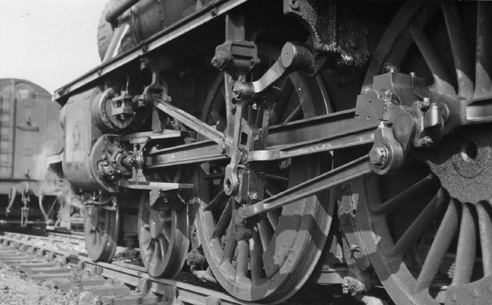
Post by michaelfive on Nov 25, 2020 11:31:16 GMT
Thank you all much for your kind help and for pointing me to the picture linking guide! I opened a flickr account, and posting pictures seams to work now. As for the axle play, I measured it between the wheels and the hornblocks. The hornblocks itselfs have a good fit in the mainframes. (Or what i consider a good fit) I just checked back and the play is different for the 3 axles of the driving wheels: The front axle is the one with the approx. 2mm play. The middle axle has roughly 1mm, and for the one in the back the play is below 0.5mm (Hard to measure) On the front wheels the bolt that holds the connecting rod is just sightly touching the driving rod:
I could easily fix this by shortening the head of the bolt and the special shim. But if the play is not correct / intended, i will rather check how i could reduce this.
|
|
|
|
Post by ettingtonliam on Nov 25, 2020 12:32:11 GMT
Are the frames parallel?
|
|
|
|
Post by John Baguley on Nov 25, 2020 18:37:14 GMT
Hi Michael,
It might be worth checking that the front driving wheels are fully home on the axles. That one in the photo looks as though it hasn't gone on all the way which would explain the increased clearance. It could be that the axle seat has been machined shorter than the thickness of the wheel though.
John
|
|
|
|
Post by runner42 on Nov 25, 2020 22:13:44 GMT
I could easily fix this by shortening the head of the bolt and the special shim. But if the play is not correct / intended, i will rather check how i could reduce this.
What you could check on the front wheels is the distance between the inside faces assuming that the wheels are at right angles to the axle. It should be 4 11/16" (this is DY's dimension so if it is not, DON'T assume that it's wrong, if different then compare it with the same measurement between the rear wheels) . This would give an indication that the front axle machining is at fault and require the front wheel set is removed and each wheel removed from the axle. This is doable as I have done the same thing. But if you reduce the head of the bolt it would be simpler. Brian PS Is the bolt in close proximity to the connecting rods on both sides or just one? There could be other issues that are causing this, too many to address at the moment until we receive more information. |
|
Gary L
Elder Statesman

Posts: 1,208
|
Post by Gary L on Nov 25, 2020 23:34:48 GMT
Yes agree with Brian's 0.020" per side, but I was wrong with the middle axle's bigger gap, it is a bit less. I think DY says 0.036" total side to side play, I ended up with 0.040" front and rear and 0.030" on the centre. Your 2mm is twice what it should be, but it might not be a problem if none of the motion gear hits anything, which is very possible. The axle boxes should not have any side play in the horns, but should be profiled to allow axle twist without side play. It is quite likely that these are a slack fit with straight cut sides. Norm In full size it was normal for the centre drivers (of 6-coupled and more wheels) to have thinner flanges and thus wider treads to give greater latitude on curves. (At least it was at Swindon). This is rarely done on models, but it seems to me to have no disadvantages. I don’t know if that was in addition to extra middle axle end float or not. The Kings had extra play in the trailing coupled axles at first, but it gave rise to rough riding and was abandoned. I can’t imagine that the leading coupled axle was ever given extra play, and the extra play in the Kings’ trailing axles was unusual enough to be worthy of special mention. Our models go round curves that are generally much tighter than scale, but there is usually plenty of slack at the flanges, which is not the case in full size. All of which suggests that while a little extra play does no harm, there are other factors that can assist and the need for it might be a bit overstated. Gary |
|
steam4ian
Elder Statesman
One good turn deserves another
Posts: 2,069
|
Post by steam4ian on Nov 26, 2020 0:04:31 GMT
Many 12" to the foot ten wheeler 4-6-0s have either flangeless leading driver wheels or increased lateral clearance on that axle. This locates the pivot points to the centre of the front bogie and between the rear driving axles.
I suggest that any lateral clearance or thinned flanges should be on the leading axle only. It appears the bolt holding the coupling rod to the leading crankpin needs some thinking through to ensure it clears the connecting rod.
Good luck. It appears a sound purchase.
Ian
|
|
stevep
Elder Statesman
Posts: 1,070
|
Post by stevep on Nov 26, 2020 9:24:50 GMT
I am not familiar with this Black Five design, but most locomotive designs have the retaining bolt for the coupling rod into the front driving wheel crank pin recessed into the rod. Specifically, I would assume, to avoid exactly this problem.
|
|
|
|
Post by Deleted on Nov 26, 2020 9:33:02 GMT
I am not familiar with this Black Five design, but most locomotive designs have the retaining bolt for the coupling rod into the front driving wheel crank pin recessed into the rod. Specifically, I would assume, to avoid exactly this problem. I concur with Steve.... this is Don Young's drawing for 'Doncaster', it follows the prototype very closely.  Pete |
|
44767
Statesman
Posts: 529
|
Post by 44767 on Nov 26, 2020 13:33:38 GMT
That looks very much like the clearance I have on my Black 5. This picture is a cross-section of the front pin on the Class 3 tank which I have drawn from works drawings. It will be a very similar thing to the Black 5 and most other locomotives.  You can see the deep recess, a special oblong-headed bolt comes through from the inside, there are two pins to stop the cap from rotating and a nut to fasten it. In 5" gauge the cap is only 0.8mm thick. I hope this helps. Mike |
|
Gary L
Elder Statesman
Posts: 1,208
|
Post by Gary L on Nov 26, 2020 21:34:24 GMT
Many 12" to the foot ten wheeler 4-6-0s have either flangeless leading driver wheels or increased lateral clearance on that axle. This locates the pivot points to the centre of the front bogie and between the rear driving axles. I suggest that any lateral clearance or thinned flanges should be on the leading axle only. It appears the bolt holding the coupling rod to the leading crankpin needs some thinking through to ensure it clears the connecting rod. Good luck. It appears a sound purchase. Ian Er, no, that’s impossible with the kind of bogie that ‘modern’ British ten-wheelers were fitted with. The de Glehn bogie for example, designed in France, adopted by the GWR and then passed to the LMS and elsewhere, offers no sideways fixed point, only a controlled degree of resistance by friction and side-control springs. Take away the guidance from the leading coupled wheel flanges (or increase the play, which amounts to the same thing), and you are relying on the rearmost two sets of flanges to keep the whole shebang steady on the rails! Some ancient locos, like single-wheelers required bogies with a fixed centre point, but I very much doubt you will find a ten-wheeler so equipped. Some really old locos (like the Broad Gauge singles) that appeared to have a leading bogie had no such thing, and relied on flexible frames to adapt to curvature. In both these cases, the (leading) drivers may have been treated in the way you describe, but you’ll struggle to find a successful modern 4-6-0 with a fixed centre bogie I think. Gary |
|
steam4ian
Elder Statesman
One good turn deserves another
Posts: 2,069
|
Post by steam4ian on Nov 26, 2020 22:38:20 GMT
Many 12" to the foot ten wheeler 4-6-0s have either flangeless leading driver wheels or increased lateral clearance on that axle. This locates the pivot points to the centre of the front bogie and between the rear driving axles. I suggest that any lateral clearance or thinned flanges should be on the leading axle only. It appears the bolt holding the coupling rod to the leading crankpin needs some thinking through to ensure it clears the connecting rod. Good luck. It appears a sound purchase. Ian Er, no, that’s impossible with the kind of bogie that ‘modern’ British ten-wheelers were fitted with. The de Glehn bogie for example, designed in France, adopted by the GWR and then passed to the LMS and elsewhere, offers no sideways fixed point, only a controlled degree of resistance by friction and side-control springs. Take away the guidance from the leading coupled wheel flanges (or increase the play, which amounts to the same thing), and you are relying on the rearmost two sets of flanges to keep the whole shebang steady on the rails! Some ancient locos, like single-wheelers required bogies with a fixed centre point, but I very much doubt you will find a ten-wheeler so equipped. Some really old locos (like the Broad Gauge singles) that appeared to have a leading bogie had no such thing, and relied on flexible frames to adapt to curvature. In both these cases, the (leading) drivers may have been treated in the way you describe, but you’ll struggle to find a successful modern 4-6-0 with a fixed centre bogie I think. Gary That depends on how much resistance, restorative force is placed on the lateral travel of the front bogie pivot. As for modern locos, a South Australian- 4-8-4 designed 1943 had a lateral motion device on the front driving axle, it was recognised as a very modern design, also very successful. Look up SAR 520 Class. |
|
Gary L
Elder Statesman
Posts: 1,208
|
Post by Gary L on Nov 26, 2020 23:58:02 GMT
Er, no, that’s impossible with the kind of bogie that ‘modern’ British ten-wheelers were fitted with. The de Glehn bogie for example, designed in France, adopted by the GWR and then passed to the LMS and elsewhere, offers no sideways fixed point, only a controlled degree of resistance by friction and side-control springs. Take away the guidance from the leading coupled wheel flanges (or increase the play, which amounts to the same thing), and you are relying on the rearmost two sets of flanges to keep the whole shebang steady on the rails! Some ancient locos, like single-wheelers required bogies with a fixed centre point, but I very much doubt you will find a ten-wheeler so equipped. Some really old locos (like the Broad Gauge singles) that appeared to have a leading bogie had no such thing, and relied on flexible frames to adapt to curvature. In both these cases, the (leading) drivers may have been treated in the way you describe, but you’ll struggle to find a successful modern 4-6-0 with a fixed centre bogie I think. Gary That depends on how much resistance, restorative force is placed on the lateral travel of the front bogie pivot. As for modern locos, a South Australian- 4-8-4 designed 1943 had a lateral motion device on the front driving axle, it was recognised as a very modern design, also very successful. Look up SAR 520 Class. Hi Not a British ten-wheeler though! In terms of the Black Five, subject of this thread, I can be categoric about it. The bogie was not a fixed centre pivot type, and no way were the leading coupled wheel flanges thinned or given extra play in the axle. A 4-8-4 is a different kettle of fish, and I imagine might have needed a bit of extra flexibility on curves. I’d be very surprised if it was as crude as thinned flanges or extra axle slop on the leading drivers though, and your answer suggests the same! Gary |
|
|
|
Post by runner42 on Nov 27, 2020 5:24:02 GMT
I thought it worthwhile providing DY's plan view of the running gear, which I suppose is accurately drawn. As you see that there is a gnat's whisker clearance between the front securing pin and the connecting rod, The drawing has omitted the hornblocks so the ample clearnance between the wheels and mainframes is not the end float, which is with hornblocks in place around 0.020". My understanding is that all three wheel sets have the same clearance and any feature to allow the locomotive to articulate rail bends is established in the wheel profiling. Brian  running gear running gear by Brian Leach, on Flickr |
|
mbrown
Elder Statesman
Posts: 1,720
|
Post by mbrown on Nov 27, 2020 10:08:56 GMT
What may appear to be a 4-6-0 or 2-6-2 etc. may in fact be fitted with an articulation between the leading truck or bogie and the leading axle. The Kraus-Helmholtz truck is one example. That would entail some side play in the leading coupled axle, but it would be constrained by the springing associated with the articulated coupling linking it to the front carrying wheels. From the outside, the loco would appear to be have a "normal" arrangement of coupled and carrying wheels.
Malcolm
|
|
Gary L
Elder Statesman
Posts: 1,208
|
Post by Gary L on Nov 27, 2020 23:24:24 GMT
I thought it worthwhile providing DY's plan view of the running gear, which I suppose is accurately drawn. As you see that there is a gnat's whisker clearance between the front securing pin and the connecting rod, The drawing has omitted the hornblocks so the ample clearnance between the wheels and mainframes is not the end float, which is with hornblocks in place around 0.020". My understanding is that all three wheel sets have the same clearance and any feature to allow the locomotive to articulate rail bends is established in the wheel profiling. Brian running gear by Brian Leach, on Flickr The drawing highlights a common misinterpretation. Remember that it is not the middle of the wheel that touches the rail! Descend to rail level and visualise the profile that is actually in contact with the rail. You will quickly see that what looks an impossibly long and rigid structure in a plan view is in reality a great deal shorter. The coning on both the flange and the tread are important elements in accomodating curvature, especially the coning of the flange, which is critical. Add in a little thinning of the flanges in the central axle (as in full-size) plus generous slop between flanges and railheads (unlike full-size) and you will quickly see there isn’t really a serious issue here. You should certainly NOT introduce slop in the leading coupled axle; your drawing shows clearly why that is never a good idea! Best of luck Gary |
|