|
|
Post by chris vine on Mar 18, 2022 13:29:08 GMT
Yes, we would love to be able to flat out our paint and then polish it back to a perfect finish.
However, as you say, Gary, rivets and bolts get in the way. But so do lots of other things like one plate on top of another, so you have hard lines. On a car, even panels at the edges of doors etc curve round the job, so making it possible to buff out the ripples/dust/insects.
The other problem is the enamel paints don't buff easily, even if rivets didn't get in the way. They take too long to fully harden. On cars, the two pack hardens very quickly and it is specially designed to be able to be cut back and polished. If it wasn't there would be lots of frustrated car painters...
Don't forget the maxim with painting: If it can go wrong, it will.
Arghh!!
Chris.
|
|
Gary L
Elder Statesman

Posts: 1,208
|
Post by Gary L on Mar 18, 2022 23:54:05 GMT
Yes, we would love to be able to flat out our paint and then polish it back to a perfect finish. However, as you say, Gary, rivets and bolts get in the way. But so do lots of other things like one plate on top of another, so you have hard lines. On a car, even panels at the edges of doors etc curve round the job, so making it possible to buff out the ripples/dust/insects. The other problem is the enamel paints don't buff easily, even if rivets didn't get in the way. They take too long to fully harden. On cars, the two pack hardens very quickly and it is specially designed to be able to be cut back and polished. If it wasn't there would be lots of frustrated car painters... Don't forget the maxim with painting: If it can go wrong, it will. Arghh!! Chris. Absolutely right Chris. There is no future in trying to buff an enamel, it is too soft. With enamel, everything depends on the lacquer layer in my experience, it is much easier to get a good sprayed gloss finish in lacquer than colour coat. I’m not really sure why, but I suspect the absence of pigment and filler allows the lacquer to flow better, and also to pull out better. Similar is true with aerosol acrylics, but you do have the option of cutting and buffing to fix a small local defect, like an errant insect. Not with a mop of course, I’m talking delicate handwork taking care to stay clear of rivets etc. But it can be done, with care. Gary |
|
Gary L
Elder Statesman
Posts: 1,208
|
Post by Gary L on Mar 19, 2022 1:30:21 GMT
One day after spraying the colour coat, and I have been able to examine the paint more closely. The cab is good, so that is put on one side to go for lacquering. The interior is well covered, but the overspray has left it distinctly semi-matt for the most part. I'm not very bothered about that, and knew it was likely to happen. I could have done the interior and exterior in two separate sessions; interior first then extensive masking before doing the outside. If the cab interior was a different colour to the exterior, this would have been the only way to go (and if you have to do this, be very sure to let the first session paint harden thoroughly before attempting to mask it). But the 15xx were black all over, inside and out, and I'm really not concerned about having a coach-gloss interior. For the outside, where I do want a full-gloss finish, I went over it with a very light touch and 1200grit wet-or-dry, doing no more than removing the odd flecks of dust. I shall only be lacquering the outside, not the interior, so I will probably mask off the interior this time, to keep away any further overspray. However quite lot of small parts, like the cab doors, and tank details will need matching treatment, so those too have been checked and de-nibbed in the same way. The tanks need a bit more work, and they are probably a better example of 'post-processing' (to borrow a name). They needed cutting back fairly severely to deal with some irregularities that didn't show up in the primer. For this, something a bit coarser than 1200grit is needed, so 600 or even well-worn 300 is more suitable. The result looks like this:  You can see that in places I have gone below the colour coat and exposed the primer and/or the knifing putty locally on both tanks. This was deliberate and it isn't a problem. Tomorrow I shall overspray those areas, to bring the colour coat back to the thickness it is everywhere else. I haven't gone below the primer and exposed the metal, but if I had, it would have needed an initial patch-in of etch primer first. You might be able to see that the rubbed-down areas are much smoother than the spray finish, particularly on the upper tank in the photo, where there are a few hollows that the w-o-d hasn't touched at all. If they worried me, I would key them with emery and build them back up with 2-pack filler (NOT knifing putty), but for reasons already discussed, I don't see the need for that degree of perfection. A word about cutting back with wet-or-dry paper (I don't know why they call it this. It is never used dry on serious work!) If you are flatting back a painted surface, you just use it with liberal quantities of water, without any backing. The water not only lubricates it, but also causes the paper to 'float' evenly above the work, thus you get an even abrasion over the whole area, and there is less chance of going in too deep. However if you are cutting back filler, or removing local bumps to fair-in the surface, then the wet-or-dry does need a hard backing pad of some sort, to make sure it attacks only the high spots, in the manner of a carpenter's plane. If it is a large and flat area, then a conventional cork or rubber sanding block will be best. With these tanks though, which are not mirror-flat, something that big would be too severe. For this job I needed something much smaller to support the paper, and I chose a small piece of 6mm waterproof ply, only about ¾" x 1½". This allows the paper to eat away the small peaks of the filler, while not attacking the broader undulations of the surface. So, weather permitting, tomorrow I will spray a bit more black to cover up the exposed substrate. Then I will leave it another day, and assuming all went well give it a very light de-nibbing, and maybe feathering-in the edges of the new paint with 1200grit wet-or-dry like the cab, before giving it the lacquer coat, which is where I will pick up this story again. And the imbecile with the silicone spray? As far as I can tell from the water coverage I have narrowly escaped the fish-eye curse, but water isn't a great test and I won't really be certain until the next coat is applied. I might try a preliminary wipe down with alcohol or white spirit, but will have to try it on a test piece first*. Watch this space. 
EDIT: *Another aspect that needs testing is whether I can safely apply the decals before the lacquer. It is better in lots of ways if it can be done, but I've had varying results in the past. Sometimes they wrinkle (disaster!), sometimes they don't. There are some spares in the pack (from Fox's) that I don't need, so I'll test one on some scrap. I suspect the wrinkling might be related to the depth of the lacquer, though the composition of it must be significant too. |
|
Gary L
Elder Statesman
Posts: 1,208
|
Post by Gary L on Mar 20, 2022 23:11:21 GMT
Club Boiler Testing day, so with all the platework in the paint shop (I use the term loosely), it was a good opportunity to get some Certificates, albeit a bit of a rush to be ready in time. Good News: the hydraulic was a pass:  Put a fire in her for the first time ever, so that is another milestone passed. Bad News: made a list of 12 rectifications, mostly minor, one of which was stronger springs in the safeties, so didn't even bother trying for a steam test. Also the RH injector didn't work, presumably because it needed a head to get it started. (The sharp-eyed reader will instantly notice that the LH one in the picture didn't even have a water connection!). But it was a fine day and nobody mentioned the Plague, so well worth the effort of getting there. Definitely the right time to submit for testing though. The rectifications will be sooo much easier before the cab and tanks go back on.
|
|
Gary L
Elder Statesman
Posts: 1,208
|
Post by Gary L on Mar 27, 2022 20:44:10 GMT
So, how goes the painting I hear you ask??Not quite as good as I'd hoped, but certainly not bad enough to start again! We left the story with the gloss black coat rubbed down in places to receive a second touch-in coat. That was done, but as usual, a certain amount of overspray caused some matting in places. This is easiest to control (in my limited experience) when spraying up to a hard external corner; pointing the aerosol towards the corner in question causes it to act as a spoiler, detaching the airflow and causing the spray to pass over the top and not settle on the just-sprayed surface on the other side. On the other hand, the rounded corners that proliferate on GWR tank engines are rather more difficult, because the rounded edges cause the airflow of the spray to follow the contours. This is all very well if you can just keep going and cover all three sides of the tanks in one continous application, but it still leaves the diffcult issue of the tank fronts, with the steps and handrail really need to be done carefully and separately. So after two or three days (the instructions say 24 hours) the second colour coat was overcoated with Halfords Bodyshop Lacquer. I sprayed the lacquer on the tank sides, bottom and top in one session, and put them on one side to dry a few days...  The camera really draws out all the faults! It isn't quite the glass-smooth finish I have had before, especially on the tank on the right, but it is good enough and I was happy with it. Then it was time to do the tank fronts, so I masked off the previously lacquered area and tackled them next. (I even put little patches of masking tape on the treads and sides inside the steps, because it is very hard to get a uniform finish in areas like that, and in real life any gloss would soon be kicked off by the fireman's boots.) Unfortunately, when removed (and never leave masking tape on till the paint is hard; it is best removed carefully while the paint is still wet, so it doesn't leave a hard edge) the main masking had left a distinct stripe in the gloss of the sides: Doh!...  The cab The cab was masked inside with cling film (useful stuff, wish I'd thought of it before!) because I didn't want a half-gloss of overspray in the interior. The lacquer coat was adequately successful:  The roof is a bit less glossy than the sides (some would say that is normal anyway), but again it was a little 'sandy' in just one place at the top of the RH cab side:  . So what to do? Well first, it is essential that the paint and lacquer system is hard-dry. Several days in the heat of the conservatory took care of that. Enter now, a miraculous substance marketed by 3M called Finesse-IT. Sadly it comes in rather large pack sizes, better suited to mopping several large boat hulls, or even cars (which is what it is designed for). It is a kind of super-mild abrasive polish, the consistency (and appearance) of slightly runny toothpaste. Other products are doubtless available, possibly in retail quantities, but this is the one I would always go for, because in use it is foolproof. It is so mild that there is no danger of cutting too deep, and it leaves a long-lasting shine. Anyway, less than a teaspoonful was enough to deal with both blemishes; you just apply it on a rag and keep rubbing lightly until it produces a shine; whereupon Job Done: The blemish on the cab side:  (Yes, the photo shows up some screw slots that I hadn't filled adequately, because in real life they are barely visible) And the RH tank front:  It is just as applicable to blemishes caused by dust, but I had very little of that. The next instalment will deal very briefly with applying the decals, and then I can start reassembling all the multifarious bits and pieces.
|
|
|
|
Post by Roger on Mar 28, 2022 9:06:41 GMT
Hi Gary,
It all looks fine to me. Trying to achieve a really good black gloss finish is the road to mental illness, in my opinion. Good enough is the right measure, and that looks plenty good enough to me.
|
|
Gary L
Elder Statesman
Posts: 1,208
|
Post by Gary L on Mar 29, 2022 18:33:27 GMT
Hi Gary, It all looks fine to me. Trying to achieve a really good black gloss finish is the road to mental illness, in my opinion. Good enough is the right measure, and that looks plenty good enough to me. Thanks Roger, and I’m sure you are right! Once or twice I wondered if I should have gone for semi-matt finish after all, but in reality it does look better in the flesh than in the photos, at least IMO. It is really disconcerting how the camera seems to magnify all the minute scratches and blips! But as several people have already said, once it is covered with soot and oil none of the defects will be noticeable (and the action of removing the soot and oil will probably add plenty more!) The finish I really want is what can be seen in the ex-works photos of 1500, but if you look closely at those, the brush marks are plain to see! And even that is unrealistic, because like you, I have included several features that were added later; and by that time there isn’t a trace of gloss to be seen in any if the old photos. I wonder if the 15xx were ever treated to the engine cleaners’ ministrations? I certainly think that the old time crews of 1501 would be pretty startled by her current limousine condition, so you might have unwittingly given yourself a more difficult standard to beat than I have! Gary |
|
|
|
Post by Roger on Mar 29, 2022 18:50:56 GMT
Hi Gary, It all looks fine to me. Trying to achieve a really good black gloss finish is the road to mental illness, in my opinion. Good enough is the right measure, and that looks plenty good enough to me. Thanks Roger, and I’m sure you are right! Once or twice I wondered if I should have gone for semi-matt finish after all, but in reality it does look better in the flesh than in the photos, at least IMO. It is really disconcerting how the camera seems to magnify all the minute scratches and blips! But as several people have already said, once it is covered with soot and oil none of the defects will be noticeable (and the action of removing the soot and oil will probably add plenty more!) The finish I really want is what can be seen in the ex-works photos of 1500, but if you look closely at those, the brush marks are plain to see! And even that is unrealistic, because like you, I have included several features that were added later; and by that time there isn’t a trace of gloss to be seen in any if the old photos. I wonder if the 15xx were ever treated to the engine cleaners’ ministrations? I certainly think that the old time crews of 1501 would be pretty startled by her current limousine condition, so you might have unwittingly given yourself a more difficult standard to beat than I have! Gary Hi Gary, Even if the finish wasn't great when it left the factory, I'm pretty sure it was Gloss Black. You're right about photos and the light. I can take two photos of the same item from a different angle, where one looks great and the other terrible. When painting, I aim for the lighting that makes it look terrible. I want to see the reflection of the light in the surface of the paint so that I can see exactly how much paint is on there. With more forgiving lighting, it's easy to fool yourself into thinking it's ok, only to find it isn't when you examine it later with a bright light. I can certainly see why people paint their locomotives with semi-gloss or even more matt finishes, because you can get away with so many blemishes that don't really show. As soon as you have a mirror finish, all that stands out like a sore thumb. However, a full gloss finish is what's on 1501 now, so that's what it's going to have. |
|
|
|
Post by martyn1936 on Mar 29, 2022 20:53:25 GMT
Hi Gary, I had the same problem with the safety valve springs on mine. As Lee Spring have a £30 minimum order charge I went through their catalogue and found three options that would work and lift at 100 psi, and have ordered a pair of each. It will be interesting to see what difference the different spring rates make to the hysteresis of the valves as they will have some effect but I don't know how to calculate that and will have to find out on the test rig.
I am sure that you are aware, but in case you aren't, the catalogue listed spring rates are for ordinary steel and the rates for stainless are lower. However their website gives the correct rates for stainless.
Martyn
|
|
Gary L
Elder Statesman
Posts: 1,208
|
Post by Gary L on Mar 29, 2022 23:01:22 GMT
Hi Gary, I had the same problem with the safety valve springs on mine. As Lee Spring have a £30 minimum order charge I went through their catalogue and found three options that would work and lift at 100 psi, and have ordered a pair of each. It will be interesting to see what difference the different spring rates make to the hysteresis of the valves as they will have some effect but I don't know how to calculate that and will have to find out on the test rig. I am sure that you are aware, but in case you aren't, the catalogue listed spring rates are for ordinary steel and the rates for stainless are lower. However their website gives the correct rates for stainless. Martyn Thanks Martyn, I'd be very interested in your results. My boiler is also pressure tested for 100psi by the manufacturer (SBW) despite being to the Adams drawings which specify 110psi. It's 'only' 10psi difference, but at the lower end of the range 10psi makes all the difference between limping and stalling, so I don't really understand why it was shell-tested at 200 instaed of 220psi. I don't suppose I'll ever know, but it is all over the boiler docs so there is no going back now. Slight digression: my Bridget runs at 120psi as Ken Swan designed it. There were plenty of naysayers ready to suck their teeth and give me dire prognostications of wheelspin and worse (No! that's what regulators are for!) but I don't see any point in running a boiler at less pressure than it was designed for. If I lose ⅔ of my boiler pressure I am still only down to the working pressure of a lot of model locos. The only disadvantage is that injectors need to be 'specials', but it wasn't difficult to get the right sort. Also it may be counter-intuitive, but safety valves are more efficient at high pressure and can have smaller apertures. At the aborted steam test the other week, one of the older and very experienced members told me that the problem was the stainless springs. He advised me to only use steel ones, saying that they work better than stainless, and that after all, it is very easy to access them and give them a protective oil spray. I expect this and my pressure comment will ignite a war, but I think I shall take his advice and see how it goes. On the subject of springs, I strongly suspect that the suspension springs are underspecified by Adams too. The loco is almost down on the stops at the moment. There is scope for tightening the springs, but not by a lot; I haven't done anything about it yet. It is a seriously heavy lump of ironmongery, and from memory, the suspension springs are stainless too, which might well be the problem. Gary EDIT. P.S.There are other spring suppliers besides Lee, they don’t all have minimum order charges. I see the last time I ordered springs was from Raymond, they were efficient, with a good range, and I don’t recall any minimum order charge. EDIT AGAIN: Update: Just been investigating a spring order from Raymond. They also have a £30 minimum order charge now, and the 2 safety valve springs I wanted took me over that |
|
dscott
Elder Statesman
Posts: 2,438
|
Post by dscott on Mar 30, 2022 0:08:20 GMT
I had a lovely drive of a Jessie last year and she went perfectly. She steamed 3 days in a row and on the Saturday began life at 5.00 and continued to about 10.00 in the evening. Her first outing, the previous 10 years had been sitting in a box. Lovely boilers.
Jessie and Bridget share the same boiler design. Yes we have one part built!
Lovely paintwork Gary.
David and Lily.
|
|
Gary L
Elder Statesman
Posts: 1,208
|
Post by Gary L on Mar 30, 2022 0:31:14 GMT
My thanks to Roger for his always-encouraging comments about the paint finish, especially since I know he is more of a perfectionist than he likes to admit! Yes, there is no doubt at all that the 15xx were outshopped in gloss black. There is a set of beautiful photos near the end of Jim Russell's marvellous book on GW Engines (vol 2), taken even before the transfers were applied. Even the smokebox was painted gloss, though in service the gloss quickly burnt off. It was probably the first and last time that No 1500 exhibited a shine, to judge from the photos, but very few of us would want to go to the length of dirtying the paint and applying oil and rust stains like they do in the 'railway layout' gauges. (We scarcely need to, when we have real soot, oil and rust on tap!) Anyway, in the last instalment, I mentioned applying the decals, and here we are:   That's it! That's all there are! There isn't a lot to be said, apart from follow the instructions on the pack. I always use Fox transfers, which are of a very high quality and accuracy, However there is a trivial tip I would offer to anyone using them for a GW 'red spot' loco. The red spot as supplied is too thin, and allows the base colour to show through and darken the red. (I expect it is the same reason why we have to apply so many coats of red on buffer beams; red pigments have inconveniently poor opacity). Fortunately, the Fox pack provides an extra set of red (actually double-reds, only used for the King class) so you can use those and apply another red spot on top of the first, which takes care of the problem. (If your model is a King, bad luck!) The second photo shows this, and also the rather handsome milled number plates supplied by David Fieldhouse. Sadly it also shows up a mistake. I'm pretty sure the plates are in the right place, which means that the holes for the seat bracket bolts are not, which is why half a hole is peeping over the top of the plate. Too late! The bolt will have to have half a head, I'm not going to mess up the paint to change it. The seat on the other side also seems to have the bolt holes in a different wrong place. There is a reason, if not an excuse: photographic evidence convinced me that the left and right hand seats are not installed symmetrically, neither as regards height nor fore-and-aft placement. It is only a matter of a few inches, but clearly my CAD drawing of the hole positions for laser cutting is out by unspecified small amounts. To anybody else using them- sorry! Back to the transfers. They must be varnished in some way; ideally using the same lacquer as for the paint, but a quick test proved this was not possible; the solvent causes them to wrinkle. Luckily there was a teaspoonful of Phoenix clear varnish left in the bottom of the 'empty' aerosol can used on the boiler, which was surgically removed and was more than enough to paint on with a camel-hair brush (2 coats). (I really must get a sable brush Bob! I did have to chase a broken hair off the work!) It is of course very important to get the transfers into exactly the right place first time. It really isn't feasible to do it by eye and chase the wet and very fragile transfer around with a brush until it looks about right. My preferred method is to mark the position with three strips of masking material to define the left right and bottom of the desired placement. Not masking tape- I won't make that mistake again! I used some Frisk low tack masking film, which is donkeys years old and had lain forgotten in a drawer all that time, but still good. To get the 'British Railways' cartouche (bar) of the lion emblem exactly level, use a plastic transparent 12" ruler and line it up carefully with the bar (rather than the tank) You can then easily see if the ruler is parallel to the tank by eye, to a high degree of accuracy, jiggling the wet transfer by tiny amounts till it is right. Finally blot the residual water away, very gently smoothing away any bubbles that might be lurking underneath. So after a day or two for the varnish to harden sufficiently, I could get on with attaching all the details. This was unexpectedly tedious, owing to the enormous number of tiny screws, all of which needed to be trimmed to exact length; but like the transfers, it is much easier to do this on the bench rather than after the unit has been installed to the loco. Here is the cab then, almost ready for final installation:  'Almost' 'Almost', because all those bare metal fastenings need to be spot-primed and painted black first, another tedious but very necessary operation. Perhaps you can make out the vertical plate in front of the RH side shutter? That is all ready to take a dummy ATC box, whenver I can get round to finding or making one. I won't feel bad about it being dummy, because its full-size counterpart on the SVR must surely be a dummy too, these days! Here's another view:  Needless to say, the next job is to assemble the tanks... |
|
|
|
Post by flyingfox on Mar 30, 2022 7:01:58 GMT
Great work, Gary, well done.
Regards
Brian B
|
|
|
|
Post by Roger on Mar 30, 2022 10:11:36 GMT
Hi Gary,
That looks amazing, and the name plates shined up like that really finish it off.
|
|
|
|
Post by doubletop on Mar 31, 2022 7:13:59 GMT
Back to the transfers. They must be varnished in some way; ideally using the same lacquer as for the paint, but a quick test proved this was not possible; the solvent causes them to wrinkle. Luckily there was a teaspoonful of Phoenix clear varnish left in the bottom of the 'empty' aerosol can used on the boiler, which was surgically removed and was more than enough to paint on with a camel-hair brush (2 coats). (I really must get a sable brush Bob! I did have to chase a broken hair off the work!) . I've had the 'wrinkle' problem with an over zealous application of spray laquer. I overcame it by a number light sprays floated on until the transfer was sealed Pete |
|
Gary L
Elder Statesman
Posts: 1,208
|
Post by Gary L on Mar 31, 2022 12:49:36 GMT
Back to the transfers. They must be varnished in some way; ideally using the same lacquer as for the paint, but a quick test proved this was not possible; the solvent causes them to wrinkle. Luckily there was a teaspoonful of Phoenix clear varnish left in the bottom of the 'empty' aerosol can used on the boiler, which was surgically removed and was more than enough to paint on with a camel-hair brush (2 coats). (I really must get a sable brush Bob! I did have to chase a broken hair off the work!) . I've had the 'wrinkle' problem with an over zealous application of spray laquer. I overcame it by a number light sprays floated on until the transfer was sealed Pete Hi Pete Yes, I've done this in the past, but I didn't want to take any chances with the rather large BR logo. Fox's instructions say that Phoenix varnish is OK, and I had a little left, so that's what I used. Interestingly (?) in my test, the 'paint' areas of the transfers were OK with Halfords lacquer applied thinly; it was the blank areas in between (that are only there to maintain the shape) that wrinkled rather badly. This wasn't a 'terminal' fault, as (with care) it could have been abraded away after the lacquer had set and the area re-lacquered. It just emphasises the need to test if you plan to use anything the manufacturer does not support. Gary |
|
Gary L
Elder Statesman
Posts: 1,208
|
Post by Gary L on Mar 31, 2022 23:17:43 GMT
Finishing the Tanks: Part 1Unlike the cab, the tanks need to be finished structurally; effectively they are just boxes without lids at the moment. Two 'lids' will actually fit on the side of each nearest the boiler and firebox, but the purpose of the lids is to allow access for fitting some of the details in a strong and watertight fashion. Before we get on to that, there is something else I wanted to fix. The tanks have a framework of 5mm plates and ¼" stringers, all in brass of course. However the water take-off is via a cock that needs to be mounted through one of the stringers, in order to give a decent length of thread for the cock to screw into. You can see this in the lower centre of the photo below:  This means that that a significant amount of water would lie in the bottom of the tanks which cannot reach the inlet of the cock, and cannot easily be drained either. I don't like the idea of this amount of dead water laying there for ever, so I decided to do what we would do on a boat, and fill in the dead space. (Traditional boats used pitch for this.) However I could usefully add a bit of extra ballast in this space as well, and I had some convenient sheet lead flashing that would do nicely. Pitch would hold the lead secure and also fill the water space, but it is rather inconvenient and smelly stuff to use, so something more modern would be better. I thought about lots of possibilities (Epoxy? -Expensive, and there would be a significant exotherm which might damage the paint. Electronic Potting Compound? -Very expensive in this quantity. Etc, etc.). Then I realised the answer was my favourite sealant, polyurethane, which is not only waterproof and very flexible, but also an excellent slow-curing glue. It cures to a firm rubber which can be painted and sanded, though neither of those qualities would be needed here. A 300ml cartidge of Puraflex 40 PU costs only £6.79 from Toolstation ("other brands are available."). It is available in black, white and sometimes grey, but black was the obvious choice here. Not shown are the masking tape 'dams' needed to prevent the PU filling the openings for the Balance Pipe. I reckoned two layers of lead flashing, loosely filling the available area would be about right, not only adding a pound or two of useful weight, but also economising on the Puraflex. It was simply a matter of guillotining the lead into strips about an inch wide. Then the PU was spread reasonably thickly and the the first layer of lead strips pressed down into it until the PU oozed up between the strips:  The lead can't cover the entire surface, because there are obstructions, including some blind nuts at the left of this picture. Then another layer of PU, another layer of lead flashing, and finally a skin of PU spread over the top and smoothed out, rather like icing a very gruesome cake:  You can see why I don't volunteer for icing real cakes! TBH, this filling was a bit of an afterthought. If I had planned for it, I would have made the lower waterways through the baffle plates (in the outer corners) a bit deeper; hence I didn't level the PU through the 'limber holes' (as they are called on boats). It will do the job fine. PU moisture-cures, and skins over in an hour or so; less if it gets a ready supply of humidity like on skin. For this reason disposable gloves are an absolute must, and change them frequently, because a little bit of sticky black PU goes a very long way given half a chance. I've put the tanks on one side to cure overnight. The cure will probably not have gone all the way through in that time, but it doesn't matter, because it can be handled safely after several hours, and won't be going anywhere. It does not flow. Cure time can be speeded up by misting with water if you are desperate and it will happily cure underwater if the need arises. (For all I know it might be possible to apply it underwater too, but I'm glad to say I've never needed to test this!) The 300ml cartidge was just sufficient to deal with both tanks by the way, though I would have been happier if I had thought to get a reserve cartridge just in case. Clean up afterwards with meths or white spirit; it is not a good idea to try to tidy up after the PU has cured. You can use soap or white spirit to lubricate the applicator if a really smooth finish is needed. PU can certainly be used to make rubber castings or moulds too, though some experimentation would be needed to find a suitable release agent.
|
|
Gary L
Elder Statesman
Posts: 1,208
|
Post by Gary L on Apr 2, 2022 22:55:41 GMT
Finishing the Tanks: Part 2Not much detailing to add to the tanks at this stage. The filler manholes and the mushroom vents will be a bit vulnerable, so they can wait till the tanks are securely bolted to the loco. So it's just the lifting rings (2 per tank) and the front top handrails. Here they are on this out-of-sequence photo: 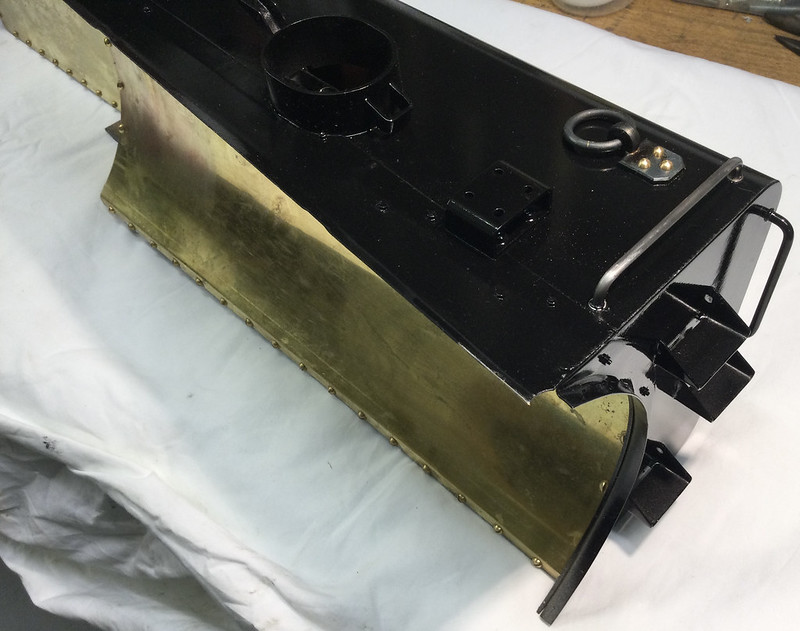 The items in question need to be sealed, so they have to go on before the inner covers, visible in the picture, are screwed on. Slotless 8BA screws are used for the lifting rings in this case. I rather wish I had been able to metal-black them, but my supply of chemicals has been exhausted, and it is rather expensive to buy a new kit just for a few brass screws, so thay will have to be spot-primed and painted instead. (The fittings themselves are steel, so they are easily heat-blacked. Unfortunately it leaves the silver solder lines glinting through, but there isn't much I could have done about that. There is no future in painting lifting rings IMO; the paint will chip off every time they jiggle around) The left-hand tank needs the gauze screen fitting over the injector water cock hole:  I shall have to hope that if ever the gauze gets blocked I can clear it by a blowing through, because it will be completely inaccessible from outside. At worst the tank would have to be removed and nearly 40 screws to remove the cover it will hide behind. Not a great service feature, but there is no alternative if the prototype layout is to be followed. The covers are sealed with transparent silicon rubber gasket material. The stuff does have its uses; the trouble is most people don't appreciate its limitations. It is pretty useless for making bead seals around baths and showers for instance, because its adhesive properties are so poor. But it works pretty well in lieu of gaskets, where adhesion is scarcely required, and it will be kept in place by pressure from the fastenings, as it will be here. Its poor adhesion is a positive benefit, because you stand a chance of separating the joint further down the line if necessary, which would be very difficult indeed with a polyurethane sealant. The ideal way is to 'cold cast' the gasket by applying it reasonably thickly and floating the mating part on top without tightening the fastenings until the silicon has cured. I have made very successful box seals this way in the past, inserting a piece of cling film to prevent any adhesion at all to one of the surfaces. Peel off the cling film when the rubber has cured and you have a nice re-usable and durable seal. However that isn't possible here; there isn't enough metal either side of the screw holes to make a reliable barrier once the screws have been turned to tighten them down, which locally breaks the joint. So there is no alternative to tightening the screws down while the silicon is still wet. I'm sure it will be fine, there is no differential expansion to consider, because everything is of brass. Here is a view of the inside face of the LH tank. Visible is the bulge pressed into the forward cover to clear the through-tank conduit tubes, and the huge number of screws; nearly 80 of them all told! The rear (flat) cover really is flat; a trick of the light gives the appearance of a semi-circular ding near the very rear, it truly isn't!  The RH tank will be almost the same, but production has paused, I've run out of screws! 
|
|
Gary L
Elder Statesman
Posts: 1,208
|
Post by Gary L on Apr 6, 2022 19:47:34 GMT
With the tanks now really tanks, not just outer shells, it is time to start assembling all the platework to the chassis. I can still hardly believe I am writing this, it is such a long time since the adventure began! First to go on is the Cab. It is fairly straightforward, and there is always the danger that if the tanks went on first, there might be trivial misalignment somewhere that would stop the cab fitting snugly. I have designed it so the cab can be detached in future relatively easily, without disturbing the tanks; this is rather important from the maintenance POV, because on scale models the fittings (and especially the boiler fittings) tend to be arranged with no regard for giant thumbs and spanners to get in amongst them. (And having to remove the tanks first, as you will see, would be first step to the madhouse) This picture shows the system; just a string of 8BA studs and nuts on either side passing through the supporting angle, a couple of 8BA screws inside the bunker rear, and then a few 12BA R/H "rivets" that hold on the cab front infills below the boiler centreline. All fairly easy to reach with a box-spanner or screwdriver respectively...  Turning then to the Tanks, I decided to follow Roger's plan of using expanded polystyrene to give a bit of extra insulation from the heat of the boiler. It can't do any harm, and might do some good. I happened to have a roll of ceiling liner (I can't recall why I had it; certainly never used it on a ceiling, but it is said to be fire-resistant so I might as well use it for this). One side has 'decorative' knobbles all over it, but nobody will see:  It is 6mm thick, but a trial fitting showed that this was too thick at the rear of the boiler barrel. Thus, the bare patch in the photo was filled with some crushable ceramic lagging left over from lagging the boiler. It was all stuck on with the aerosol upholstery adhesive in the photo. (Just a light coating is best on the polystyrene, because the adhesive solvent eats it.) That done, the tanks were gingerly offered up to their final home. The string around the chimney is to make sure no accidents happen before the screws can be fitted!... 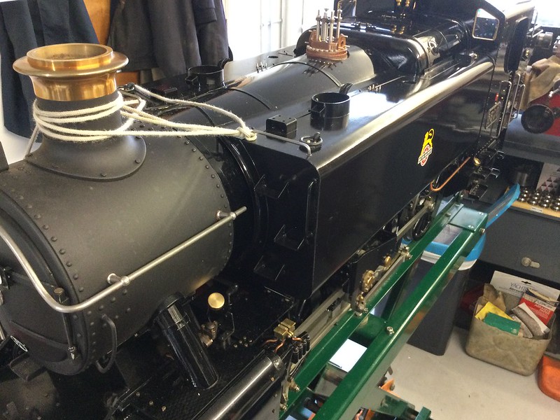 This job really was as hideous as I expected. See remarks above about scale models and thumbs! There are dozens of little nuts and screws, all to be attached in the prototypical places. I'm guessing that the full-size fitters struggled with some of these bolts, even without having everything miniaturised around them! Here's just one example:  What you can just about see (arrowed) are the heads of a pair of 6BA stainless screws. What you can't see are the contortions necessary to screw them in, involving balancing each screw on the back of a screwdriver blade (double-sided tape helps a little), then prodding with a scriber to try and engage the thread. After much expleting, there is just the small task of getting the spanner on each head, quarter-turn at a time because the edges of the mounting bracket foul the spanner head (of course) which has to be reversed for the next movement... and that is just one done! Oh I forgot: the balance pipe has to be attached first, and the cross-tie girders have at least to have the bolts engaged, because the clearances are so tight. In fact every bolt needs to be engaged, for fear some won't engage if others are tightened too early. Yes, that is standard engineering practice, but there are so many of the damn things, all of them in awkward places; some can only be offered up with fine-nose tweezers! AAARRGH! So, many hours later, all the main units are securely attached, and I can step back and see what looks like a real locomotive, properly dressed, just needing cufflinks and a few accessories... 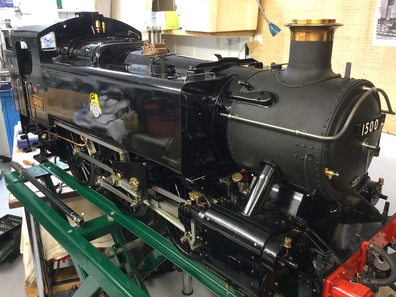 Then the bits that hold the water in can be attached to the tanks, so that a water test can be carried out. This view shows (amongst other things) the array of test cocks on the LH tank, with below them, the handle for the injector water valve. The test cocks do actually work, though whether they will get used is much more doubtful (easier to take a peep down the filler manhole -one thing that the full-size crew couldn't do so easily)  Poured in the first litre of water, no weeps visible, so poured in some more and then the dreaded trickling noise could be heard; with confirmation from the wet socks... Nothing for it but to place a bucket and fill up the tanks (8.7 litres, since you ask...) and then do a good check round for any other leaks, of which happily there were none. This one might be the one and only, but it is going to be a brute to fix:  It is on the RH flange of the balance pipe, at the one stud hole where it is almost impossible to get a spanner on the nut, due to the proximity of the throatplate and the sander bell-crank. DOH! Off now to lie down in a darkened room. More news when (if) sanity returns... |
|
|
|
Post by Roger on Apr 6, 2022 20:45:50 GMT
Looks great Gary. I'm not so sure about the Expanded Polystyrene though. I did a test with some of it that's backed with a thin card, holding it against the surface of the test boiler, and it melted. You might get away with it if there's another insulator between it and the boiler, but I'd hate for it to stick to the boiler barrel and spoil the paint.
|
|


