Gary L
Elder Statesman

Posts: 1,208
|
Post by Gary L on Oct 5, 2020 22:56:12 GMT
Paddington is a 7.25 inch gauge WR Hawksworth 15xx 0-6-0PT designed by David Adams in 1984. To call it a ‘big Speedy’ doesn’t do justice to the detail and (relative) accuracy of the Adams model, though, that said, the drawings are littered with dimensional mistakes, even where dimensions are given at all, which is not always the case… I took over this project early in 2016 from a very good engineer who had done all the difficult bits. “Check every dimension twice” was his advice and very sound advice it was too! Completing the mechanicals would have been a great deal more difficult without Roger’s inspiration and kindness in sharing his extensive photo archive, and without the assistance of Barry Leach now sadly departed, of Cheltenham SME whose ‘errors’ blog is still available at www.cheltsme.org.uk/index-paddington_project.html The loco looks like this at present, a bit naked:    Bar connecting up the pipes to the top feed she is ready for a steam test, but that can wait a while yet. The real challenge now is the platework; adding the cab and tanks. This is because (1) I hate platework (2) I’ve not much experience with it and (3) Swindon-style tanks and cabs involve all sorts of curves in awkward places. (4) Did I mention I don’t enjoy platework? So this is not a “how-to-do-it diary”; it will be more a case of “Please, how on earth do you do it?” More soon... Gary |
|
dscott
Elder Statesman
Posts: 2,438
|
Post by dscott on Oct 6, 2020 1:42:32 GMT
They are indeed a FULL SET of Drawings but as said need checking.
Friend Alan built one several years ago and this goes as well as it looks.
He got given lots of old worn Carbide tips and the tip he gave is to tip them in the tanks. Couldn't resist.
Still hold water but the weight and adhesion is superb.
I got my drawings from someone in Didcot who had begun to dimension everything for 5 inch.
Currently I am working on a begun Butch Twin Sisters. Strange that Twin Sisters came out years ago and Butch follows so many same dimensions. The twins were done to the old 1 inch scale so buffers will look strange.
BUT. Being close to scale, I am just re drawing them to 1 1/16" scale. First thing that you get is a slightly bigger loco. 2 1/4" more.
Then it hits you that the JINTY boiler will now fit if you slightly extend into the cab. This is so Dock Tank.
I sent so many drawings and photos to Roger to assist the Wonderful Project.
Mine is much slower but I do bits when set up to do them.
I love platework and learned so much from a retiring expert with 36 years in a Prototyping Workshop.
I absorbed.
Then went on to teach it all as a Technician in Plymouth Uni for the next 23 years.
David and Lily.
|
|
|
|
Post by simplyloco on Oct 6, 2020 7:34:27 GMT
SNIP The real challenge now is the platework; adding the cab and tanks. This is because (1) I hate platework (2) I’ve not much experience with it and (3) Swindon-style tanks and cabs involve all sorts of curves in awkward places. (4) Did I mention I don’t enjoy platework? So this is not a “how-to-do-it diary”; it will be more a case of “Please, how on earth do you do it?” More soon... Gary Hi Gary I love your pipework, a job I dislike! However, I like platework, and if you fancy a day out you are welcome to bring some sheet metal and a drawing and we could have a look at your cab! Cheers John |
|
|
|
Post by Cro on Oct 6, 2020 11:33:22 GMT
Looks beautiful Gary, I love platework and pipe work - when its going my way.
Any close ups of the backhead bits mainly the brake valve?
Adam
|
|
Gary L
Elder Statesman
Posts: 1,208
|
Post by Gary L on Oct 7, 2020 0:15:12 GMT
Looks beautiful Gary, I love platework and pipe work - when its going my way. I rather like pipework... if you make a mistake you throw it away and make another bit! But platework... somebody's got to like it I guess (shudder!) Any close ups of the backhead bits mainly the brake valve? Adam Like this one Adam?  'Course there's no telling if the brake valve actually works...  It is a little different from the standard Cro version, because I wanted it to have a lap function and cut off the suck from the ejector, so it has a backplate with an extra flange to take an extra pipe and make it a little easier to mount. -Gary PS. The regulator handle now has a nut! PPS. No apologies for the amount of proprietary fittings on this backhead! There is more than enough for me to do on this project without having to do a lot of intricate work that somebody else can make professionally better and quicker than I can! |
|
Gary L
Elder Statesman
Posts: 1,208
|
Post by Gary L on Oct 7, 2020 0:18:15 GMT
SNIP The real challenge now is the platework; adding the cab and tanks. This is because (1) I hate platework (2) I’ve not much experience with it and (3) Swindon-style tanks and cabs involve all sorts of curves in awkward places. (4) Did I mention I don’t enjoy platework? So this is not a “how-to-do-it diary”; it will be more a case of “Please, how on earth do you do it?” More soon... Gary Hi Gary I love your pipework, a job I dislike! However, I like platework, and if you fancy a day out you are welcome to bring some sheet metal and a drawing and we could have a look at your cab! Cheers John Thanks John, though I hope the sheet metal cutting is largely taken care of. (See next exciting episode!) It is the bending where the fun will start! Gary |
|
Gary L
Elder Statesman
Posts: 1,208
|
Post by Gary L on Oct 7, 2020 0:27:10 GMT
They are indeed a FULL SET of Drawings but as said need checking. Friend Alan built one several years ago and this goes as well as it looks. He got given lots of old worn Carbide tips and the tip he gave is to tip them in the tanks. Couldn't resist. Still hold water but the weight and adhesion is superb. I got my drawings from someone in Didcot who had begun to dimension everything for 5 inch. Currently I am working on a begun Butch Twin Sisters. Strange that Twin Sisters came out years ago and Butch follows so many same dimensions. The twins were done to the old 1 inch scale so buffers will look strange. BUT. Being close to scale, I am just re drawing them to 1 1/16" scale. First thing that you get is a slightly bigger loco. 2 1/4" more. Then it hits you that the JINTY boiler will now fit if you slightly extend into the cab. This is so Dock Tank. I sent so many drawings and photos to Roger to assist the Wonderful Project. Mine is much slower but I do bits when set up to do them. I love platework and learned so much from a retiring expert with 36 years in a Prototyping Workshop. I absorbed. Then went on to teach it all as a Technician in Plymouth Uni for the next 23 years. David and Lily. As with Speedy, the 15xx is an excellent subject for a model that has to do some real work. A tank engine so reasonably compact, but all the motion outside the frames- there aren't so many prototypes for that. Potentially plenty of power, and a taper Belpaire boiler so should steam well too, with a bit of luck. And finally it's a Swindon design as all proper engines should be... The trouble lies, of course, in both cases with the plans. Roger has found that too. Gary |
|
dscott
Elder Statesman
Posts: 2,438
|
Post by dscott on Oct 7, 2020 0:47:04 GMT
Yes I did a set of drawings for the frames and Roger has many Photos he took of them.
There are so many holes to drill not on Speedy. Also 5/16" which is quite a big measurement.
This is how much wider the frames are compared with scale ones. Another reason for Speedy not looking quite right!
I am doing 2 of them when I have a purge.
Frames of Great Western Locomotives are a certain width? And all the same?
Yes they were limited by the size of the equipment they were cut out on!!!! Makes sense.
Yes I had a misspent Youth in Keith Wilson's Workshop. 1975 onwards.
Was at School with his son Alan. Felow Librarians.
I built a lathe for A Level as you do. Myford size.
David and Lily.
|
|
Gary L
Elder Statesman
Posts: 1,208
|
Post by Gary L on Oct 7, 2020 1:05:25 GMT
...So step 1 was to draw the ‘difficult’ parts in CADintosh and then get them laser cut by Malcolm High. There are a number of scale inaccuracies in the Adams platework drawings, as well as a number of arithmetical errors, so I went back to the dimensioned Swindon drawings and started again. It took quite a while! I decided to mark out nearly all the rivet and handrail holes for cutting, slightly undersized. I hoped the small holes would not interfere with smooth rolling of curves; it is very early days, but so far so good. Also some of the parts could not be cut to size in every direction, because of the need to allow some waste metal for rollers to grab hold of (if only I could get the hang of using them!  ) My model will be number 1500, because there are some good works photos available. I also referred to Roger’s extensive photo library of 1501, but there are a number of detail differences between the two examples, it’s a minefield. I surprised myself by ending up counting rivets; it is just as easy to use the right spacing as the wrong, so might as well start off right if possible. In the process you learn what the rivets were for and how the original was put together, so it isn't a total waste of time, unless you already have a life... The 15xx was distinctly transitional in its construction. There is hardly any welding in the cab and bunker, which are riveted throughout, closely following GWR conventions from the 1930s. The tanks though are entirely welded, which makes our life slightly easier, except for people who want to reproduce welded seams. I doubt if that is me! Here is the set of plates as delivered from MEL. First the cab plates:  And the tank plates:  I was very pleased indeed with the results; the high degree of accuracy that laser cutting gives should make achieving those pesky curves easier by having an accurate template from the beginning. Even the rivet holes were spot on to the diameters as drawn. Malcom says laser cutting can go down to 0.1mm, which is a much finer cut than I was expecting. It also cuts the edges dead square, which is handy for certain of the small items where silver soldering an angle or a tee is required. I've already done three of those, but won't get ahead of myself. Obviously I didn't bother with the straightforward rectangular plates with no rivet holes, notably the tank sides. But they are a job for much later, and I am somewhat dreading them. |
|
dscott
Elder Statesman
Posts: 2,438
|
Post by dscott on Oct 7, 2020 1:24:43 GMT
Beware sheet 4 and Sheet 11. From the Cheltenham Web site. Useful.
Traveled behind 1501 several times, including the last late running train on the GWR to Cheltenham.
Leading coach of course and setting a new speed record for the line.
Found out just WHY they were used on EMPTY STOCK ONLY and the boiler on the model is so good.
I am expecting 2F Dock Tank to have similar property's.
Twin Sisters drawings are on a par with Asia drawings. Many reach a stage and do not proceed.
Simplex is pants with the boiler to cylinder ratio out. Bulldog is too simple with not enough detail and the valve gear is out.
Jinty needs re working. Far too many mistakes.
Station Road Steam has a super web site with an Archive which gives great detail and stages and rough numbers built of each model.
Large Prairie is perfect but there are not enough hours in the day.
I own the Ultimate build instructions for one!!! A 60th Birthday present.
David and Lily.
EDIT.
WOW what a thing to get through the post.
They are beautiful.
|
|
|
|
Post by Cro on Oct 7, 2020 7:51:17 GMT
Gary, looks great! Can't wait to see it all coming together.
Adam
|
|
smallbrother
Elder Statesman
Errors aplenty, progress slow, but progress nonetheless!
Posts: 2,269
|
Post by smallbrother on Oct 7, 2020 8:18:47 GMT
What a fabulous job you have made of that. I have seen one perform at a rally and it was one big and very powerful beast.
Pete.
|
|
kipford
Statesman
 Building a Don Young 5" Gauge Aspinall Class 27
Posts: 566 
|
Post by kipford on Oct 7, 2020 16:04:05 GMT
Gary
Laser cutting always results in a tapered edge, top edge to size, bottom slightly under. It is just that in thin gauge materials it is barely noticeable. However beware of the effect when you start getting above about 5mm thick.
Dave
|
|
Gary L
Elder Statesman
Posts: 1,208
|
Post by Gary L on Oct 7, 2020 17:07:48 GMT
Beware sheet 4 and Sheet 11. From the Cheltenham Web site. Useful. Traveled behind 1501 several times, including the last late running train on the GWR to Cheltenham. Leading coach of course and setting a new speed record for the line. Found out just WHY they were used on EMPTY STOCK ONLY and the boiler on the model is so good. I am expecting 2F Dock Tank to have similar property's. Twin Sisters drawings are on a par with Asia drawings. Many reach a stage and do not proceed. Simplex is pants with the boiler to cylinder ratio out. Bulldog is too simple with not enough detail and the valve gear is out. Jinty needs re working. Far too many mistakes. Station Road Steam has a super web site with an Archive which gives great detail and stages and rough numbers built of each model. Large Prairie is perfect but there are not enough hours in the day. I own the Ultimate build instructions for one!!! A 60th Birthday present. David and Lily. EDIT. WOW what a thing to get through the post. They are beautiful. Hi David I've never seen 1501 in steam, let alone travelled behind her. (In fact the last time I saw a 15xx in steam and in the flesh was at Paddington station!) But I've seen videos, and the -um- lively motion is inescapable. The 25mph Light Railway speed limit is probably what makes her allowable on non-empty stock! Never mind, in miniature size I never had any such problems with Speedy, and hope Paddington will be similar. The 15xx has (almost) the same boiler as the 2251 class 0-6-0 which was also a strong performer I believe in full-size. It means it should be possible to use the model boiler from Polly's 2251, which is a later and better design than Paddington's, especially WRT the firebox proportions. It isn't so simple unfortunately, because the 2251 is built to a scale of 7.25:56.5 rather than straightforward 1:8 so the scale boiler would have to be scaled Sadly my boiler is more or less true to the Paddington drawings, with a few unnecessary features omitted. It is hard to be kind about faulty drawings when they lead to wasted time and money, but if we were only allowed perfect drawings on the market (pre-CAD) we would probably be limited to Ken Swan designs! The real offence is that faulty drawings continue on sale for decades with notorious faults and the publishers don't even seem to issue 'errata' sheets, much less get them corrected. (As has been said in these pages many times before...) -Gary |
|
Gary L
Elder Statesman
Posts: 1,208
|
Post by Gary L on Oct 7, 2020 17:10:09 GMT
What a fabulous job you have made of that. I have seen one perform at a rally and it was one big and very powerful beast. Pete. Thanks Pete, but sometimes the camera is kind! Gary |
|
Gary L
Elder Statesman
Posts: 1,208
|
Post by Gary L on Oct 7, 2020 17:11:30 GMT
Gary, looks great! Can't wait to see it all coming together. Adam Thanks Adam, me too, but it won't be quick Gary |
|
Gary L
Elder Statesman
Posts: 1,208
|
Post by Gary L on Oct 7, 2020 18:15:14 GMT
Gary Laser cutting always results in a tapered edge, top edge to size, bottom slightly under. It is just that in thin gauge materials it is barely noticeable. However beware of the effect when you start getting above about 5mm thick. Dave Interesting. The thickest plates in my order were 5mm thick, so I have just gone out and examined them very closely! I would say the last half-millimetre is indeed very slightly 'soft' in the way you describe, but it is hardly detectable; you have to look very hard to see it, and it won't affect the squareness of the build. The bulk of my material is 1.5mm brass, so no issues there at all. To my slight surprise, I found it was possible to clamp and silver solder some smallish angle and tee components and the crisp edge of the cut was sufficient to produce a reliably square result with no other precautions, which in itself was a revelation to me. With the very fine slot, it is also possible to cut access hatches and their infill cover in the same cut- which I don't think is possible with any other technology. Not that I needed to do that in this order, but I could have used it in the steel footplate, had I realised. I believe that water-jet cutting can have more pronounced tapering unless compensated for in the process, but that is something I have even less experience of. I know there are issues with edge-hardening of steel using laser cutting, but with brass it seems to me it ticks every box, in spades. I don't have the skills or the equipment to cut plates like Roger does, so I am a total enthusiast for laser-cutting now. The price was also very reasonable; I don't think I would have saved a huge amount by trying to hack sheets of raw brass, so why bother? Gary |
|
Gary L
Elder Statesman
Posts: 1,208
|
Post by Gary L on Oct 7, 2020 20:33:45 GMT
The first plate I wanted to tackle is the lower bunker panel that curves round at both outer corners to meet the cab sides. Hopefully the bending allowance was done correctly, because having already defined the rivet holes both sides of the joint with the side panels, there is not much scope for adjustment if the join then comes at the wrong place longitudinally! On 1501 this panel is made in 2 parts, joined at the CL, but photographic evidence is very clear; on 1500 the originals were made in one complete piece: There is a curious feature in the 15xx whereby the bunker lower panel sits on top of the footplate, which protrudes 2” beyond the bunker to mount the lamp irons on. The cab sides though, overlap the footplate, and the place where the change occurs seems to be at the joint between the two panels, requiring a notch in the footplate. The evidence from 1501 is a bit inconclusive, and there has been much replacement and refurbing in this area, but that is my interpretation, and it makes sense structurally. The prototype footplate is a great deal more complex than mine, and nowhere is it just a flat steel plate. The full-size assembly is around 2½ inches thick, (and more than double that in places!), which Roger has replicated in solid metal, but on mine I’m content with a plain 16g plate, though I have cut access holes in it which correspond roughly to similar features on the prototype. This will be a working model, where coal, oil, water and paraffin will be sloshing about, so it needs to be easy to keep clean. The general idea is that the cab and bunker will be removable as a unit, bolted through ¼” brass angles to the 16g steel footplate. So the first job on the plate was to clamp a length of angle to the lower edge, and through-drill all the rivet holes. These will be 1/16” dia. In full-size the mounting angles are curved to follow the contour of the corners (4" radius which scales to 7/16” radius at the inside face of our nominal 16g plates) I judged this to be Too Difficult to be Worth Bothering as it will be very hard to see, so I just cut the angle short where the bend would have been. The next task (which did bother me a lot) was to anneal the plate where the bends would come. I knew I didn’t have the equipment to anneal the whole plate without distorting it, even if I wanted the whole thing to be softened. In the event, I laid it on an insulation block, and covered the central portion with another block, so only the two outermost margins were exposed to the direct flame. After heating to red heat, the annealed part was also covered with a brick, and then left to cool naturally and slowly. This was then repeated at the other end of the plate, and to my great relief, I then had a perfectly flat sheet with soft ends. I didn’t photograph this, as I wasn’t planning on starting a build thread at the time! I had previously (a long time previously!) made a special jig for the next operation; basically two lengths of 7/8” dia steel rod brazed to a ½in plate at the exact distance required. Then with the aid of a few toolmakers clamps and firm downward pressure on a flat bench, it was possible to bend the corners to suit. It was necessary to anneal again half-way, because no ‘spring’ can be tolerated, or the bend will not be true to the former. The discoloured annealed sections can be clearly seen in the pix below: 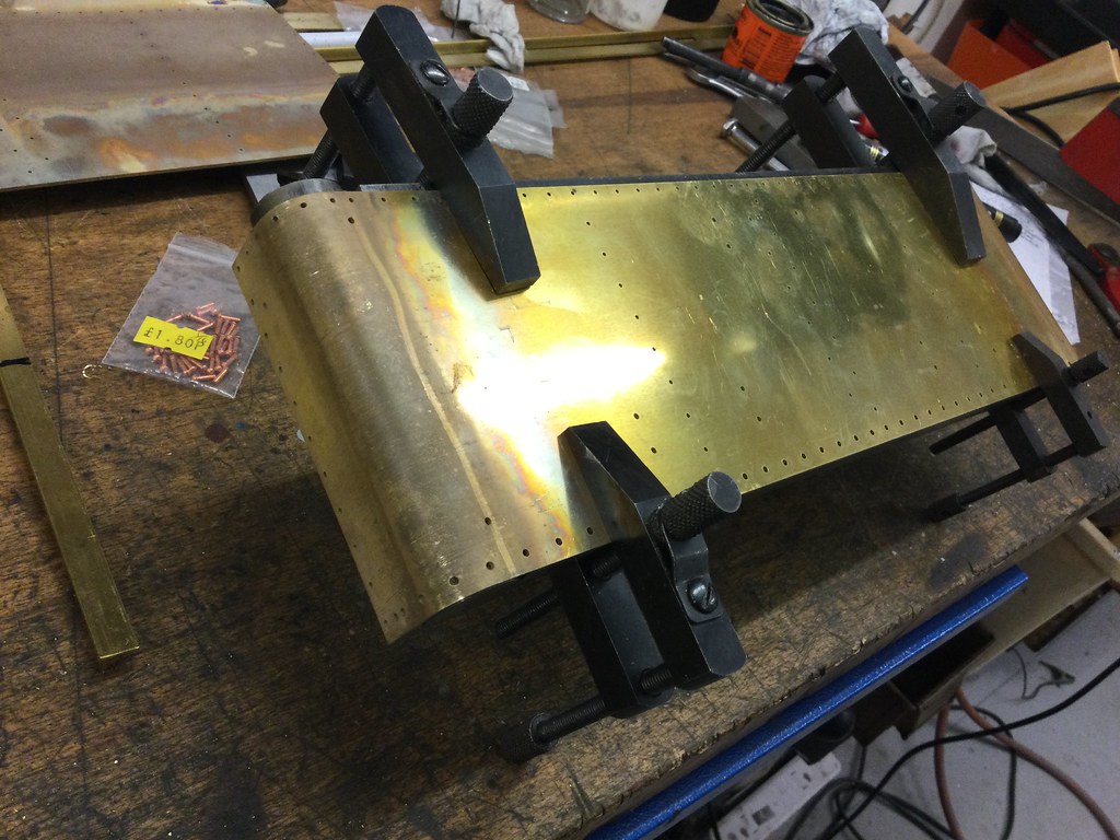   When I had completed the bend to about 88 degrees, it was almost, but not quite matching the profile of the jig, so I removed the clamps and gingerly bent the last couple of degrees by hand against the flat bench. Lo and behold, this tightened up the radius to the exact profile required! A quick check against the footplate, and it comes exactly to the pre-ordained notch. That was a definite morale-boost, as it proved the bend allowance calculations as well!  I should add that I’m a hopeless mathematician, so I had used the online calculator at www.custompartnet.com/calculator/bend-allowanceA great help to we of the well-intentioned but numerically challenged tribe! Gary |
|
|
|
Post by Deleted on Oct 7, 2020 20:41:23 GMT
Superb work Gary, GWR is foreign to me but it looks like you got those curves spot on.
Pete
|
|
Gary L
Elder Statesman
Posts: 1,208
|
Post by Gary L on Oct 7, 2020 22:08:56 GMT
Superb work Gary, GWR is foreign to me but it looks like you got those curves spot on. Pete Always like to hear encouraging comments like that Pete, but it was Beginners' Luck! And no rolls involved! The plate that sits above it has two curves running the full width of the loco, (which amounts to over a foot for those used to working in smaller gauges). One curve is quite a large radius (2.25" inside x 11.5" long), then immediuately above it is a very tight reverse bend (⅛" inside radius). It will just fit my 12" rolls, but getting a bend of consistent radius is something I haven't got the hang of at all. And not only that, it has to be the right radius in the right place! As I'll explain in the next thrill-packed instalment, I've managed to do it with the support angles that amount to a template for the bend, but only with a lot of finger-and-thumb work. Can't do that over 11.5 inches though! Hmmm  Gary |
|


 )
)