|
|
Post by jon38r80 on Jun 23, 2021 8:22:32 GMT
To get better weld penetration in a case like that where you can only weld from one side it is normal to prep the vertical piece with a 45 degree chamfer so that the root pass can almost fuse the far side and the rest of the ‘ cavity’ filled with subsequent overlapping passes. It’s a bit late for that now I know , sorry to have been late with that. If you can beg steal or borrow a Lincoln Arc Welding book for the future it’s worth a squint.
|
|
|
|
Post by Roger on Jun 23, 2021 10:00:52 GMT
To get better weld penetration in a case like that where you can only weld from one side it is normal to prep the vertical piece with a 45 degree chamfer so that the root pass can almost fuse the far side and the rest of the ‘ cavity’ filled with subsequent overlapping passes. It’s a bit late for that now I know , sorry to have been late with that. If you can beg steal or borrow a Lincoln Arc Welding book for the future it’s worth a squint. Hi Jon, That's a good point, I hadn't even considered welding it from one side. My dear friend Bill is coming across tomorrow to have a look at welding the inside using stick welding. I bought some 2.5mm rods today, but I'm told those won't be big enough. Anyway, Bill has tons of experience and welding rods of all sizes, so I'll lean on his expertise. |
|
|
|
Post by Roger on Jun 24, 2021 21:25:53 GMT
My dear friend Bill came to the rescue this morning, and suggested that the two end pieces could be welded onto the face of the large plate so that is would resist it bending. It had already bent a little with my welding, and this would help keep it straight.  20210624_100549 20210624_100549 by Georgia Montgomery, on Flickr Bill's welding skills are amazing, and this is how it looked using 3.2mm sticks, 115Amps, and 50 years of experience. The inside looks just as good.  20210624_110512 20210624_110512 by Georgia Montgomery, on Flickr The end plates were removed using an angle grinder and hammer, and here is the first one being tacked to the bridging plate.  20210624_151520 20210624_151520 by Georgia Montgomery, on Flickr Then the piece was carefully balanced in place and tacked using the stick welder, this time I'm on my own again.  20210624_154015 20210624_154015 by Georgia Montgomery, on Flickr The second side was held with a wedge and a piece of M12 rod for tacking. 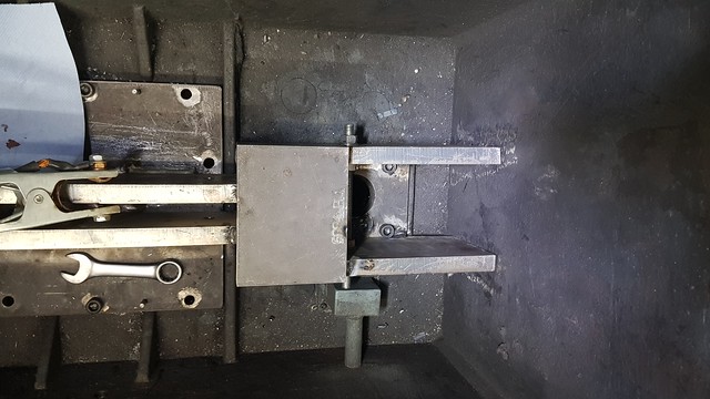 20210624_155652 20210624_155652 by Georgia Montgomery, on Flickr The plate is joined corner to corner because it has to clear the cast iron webs. The weld is small, but pretty strong. 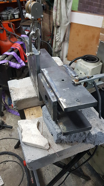 20210624_205539 20210624_205539 by Georgia Montgomery, on Flickr 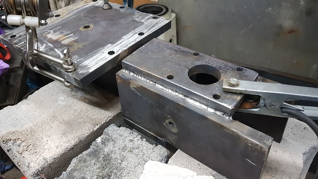 20210624_211753 20210624_211753 by Georgia Montgomery, on Flickr I've used the stick welder on the inside. It's not pretty, but it's strong. 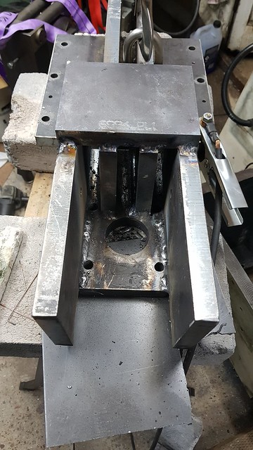 20210624_215523 20210624_215523 by Georgia Montgomery, on Flickr This is now complete, so I'll do one final trial fitting in the morning when it's cooled off. I've bought this Devcon for setting the stiffener into the casting. I'll mix up the whole 500g tub since I'm only going to get one go at it. |
|
|
|
Post by Roger on Jun 25, 2021 22:30:58 GMT
It's finally the point of no return. I mixed up the whole 500g of the Devcon and ladled it on with a wallpaper scraper. The four M12 bolt holes on the right have some round foam draught excluder in them, and the others have some Delrin plugs I turned up. I could see the Delrin running everywhere, especially down the holes, so I thought that would keep it in place at least while I was pouring it. The Devcon is a lot more runny than the Aluminium Putty I normally use. This stuff has a very thin activator which makes it so then it's mixed in. Ideally I should have bought a loat of plasticine and made a retaining wall.  20210625_214404 20210625_214404 by Georgia Montgomery, on Flickr The plugs were swiftly removed and the plate dropped in place. The dowels were then tapped down and the four M12 Cap Screws on the right were pulled down and then released slightly. The same goes for the two bolts that hold the plate under the column.  20210625_222001 20210625_222001 by Georgia Montgomery, on Flickr Hopefully the putty has mostly stayed in contact with the plates. I didn't bolt it all down tight because that would only introduce stresses. I'll only do that when it's fully cured and the column is in place. The Devcon ran down the bore where the Leadscrew nut goes, so I had to give that a good wipe with paper towels to get rid of it. Anyway, what's done is done, it's too late to change my mind now. As long as there's a decent amount of Devcon around each bolted area, this ought to work well. The weight of this structure is considerable, and it's very stiff. I'll be interested to see how much the base flexes. Place your bets, it was 40microns before this. My guess is 5microns. |
|
|
|
Post by Roger on Jun 26, 2021 19:58:58 GMT
Fortunately the Devcon hasn't just run out of the joint. Here I've just cleaned it up with a scraper, but there wasn't much there. I did run a drill through the holes though, some had inevitable got into those.  20210626_101105 20210626_101105 by Georgia Montgomery, on Flickr So it was back onto its side, and mated with the column. I slipped up by not greasing the four M12 cap screws, and I can only move two of them. It's annoying because I had intended doing it, and simply forgot! They were all just nipped up, but in reality, it's bonded so tightly that I don't suppose it's going to matter that only two were additionally tightened. I couldn't add any significant force in any case.  20210626_104551 20210626_104551 by Georgia Montgomery, on Flickr I drilled and tapped the edge holes on the front... 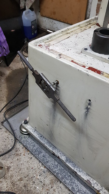 20210626_121226 20210626_121226 by Georgia Montgomery, on Flickr ... and back, so the stiffener is attached right across from front to back now.  20210626_150804 20210626_150804 by Georgia Montgomery, on Flickr The leadscrew was a bit tight near the bottom of travel, so I knocked the housing free of the original Devcon and cleaned that up with a scraper and some solvent.  20210626_201356 20210626_201356 by Georgia Montgomery, on Flickr Here I've added some new Devcon and it's lightly nipped up. This Devcon is nowhere near as strong as the other type, so I won't have any trouble finally tightening them. I've moved the knee most of the way to the bottom to make sure it won't bind any more. Hopefully it won't be far out at the other end of travel. It's not such a big issue when the leadscrew is extended, there's more flexibility.  20210626_203617 20210626_203617 by Georgia Montgomery, on Flickr Anyway, that needs to go off overnight, and then I can start reassembly proper. |
|
|
|
Post by Roger on Jun 28, 2021 15:50:46 GMT
I've managed to get the machine back together for some tests today. This is the Servo response for the X-axis which is pretty good. The Blue and Red plots on the graph are very close indeed, which is exactly what we want. The Blue plot is the output commanded by the control, and the Red plot is the actual position being read in realtime from the linear scale. The Green plot is the modified output from the PID control loop that's making that happen.  X-axis Step response1 X-axis Step response1 by Georgia Montgomery, on Flickr This is the same data, but this time with the difference between the Blue and Red plots on the previous graph so you can see the errors magnified. The I may be able to reduce the spike at the start and end of the motion, but it's a good starting point. At no point is it more than 60microns (just over 2 thou) out even when it's accellerating from a standstill flat out. 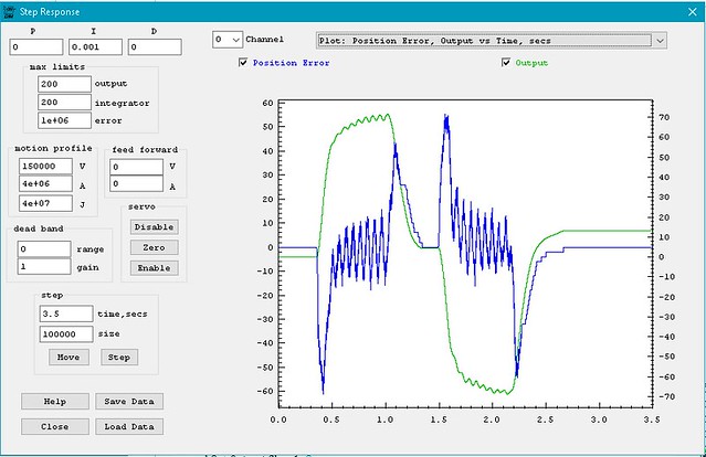 X-axis step Response X-axis step Response by Georgia Montgomery, on Flickr However, there's a big problem with the Z-axis, even though this doesn't look too bad. You can see the Blue plot leads the Red plot, and that's not right.  Z-axis step response1 Z-axis step response1 by Georgia Montgomery, on Flickr Blown up, it looks horrendous, because it is. The vertical scale is in microns, so that's nearly 0.2mm of lost motion somewhere.  Z-axis step response Z-axis step response by Georgia Montgomery, on Flickr Anyway, back to the purpose of completely stripping down the machine... Here I'm checking the deflection of the leadscrew support, which last time deflected by 40microns as it accellerated the knee upwards. This video shows the deflection with the same Servo parameters  20210628_155816 20210628_155816 by Georgia Montgomery, on Flickr Here's a more aggressive set of parameters. 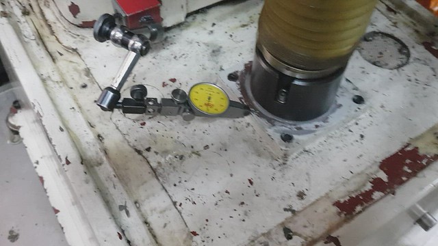 20210628_160025 20210628_160025 by Georgia Montgomery, on Flickr Clearly that's not the problem. I also put the clock on the top of the nut to make sure that's not moving. So here's another test. I wondered if the knee was too free, and that the casting was tipping. Since the Linear Encoder is about 200mm from the centreline of the leadscrew, that could be a significant error.  20210628_161241 20210628_161241 by Georgia Montgomery, on Flickr However, this video shows that there's next to no movement of the knee towards the column, so it's not that. 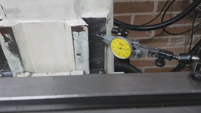 20210628_161207 20210628_161207 by Georgia Montgomery, on Flickr So I'm left with the conclusion that although the leadscrew thrust arrangement it done up tight, it looks like there must be something amiss. Anyway, it's clearly got to come apart again, so I'd best get on with it. |
|
|
|
Post by jon38r80 on Jun 28, 2021 18:25:52 GMT
Frustrating after all the thought and effort you have put in.
|
|
|
|
Post by Roger on Jun 28, 2021 18:51:22 GMT
Frustrating after all the thought and effort you have put in. That's Engineering and Development for you. Actually, I'm pretty pleased so far, the stiffener has completely solved the flexing of the base. Hopefully this is a simple issue that I can fix. I suspect it's been like this from day one, but I just haven't been able to see it. |
|
|
|
Post by Roger on Jun 28, 2021 22:32:53 GMT
Having just taken this apart, I could see a quick way to get the Z-axis apart. I've parked it with the Y-axis to the back, and the Z-axis at a height where I can prop up the knee with the Aluminium block. Then it was just a matter of releasing the Y-axis motor assembly and pulling the table forward. That moves the Y-axis leadscrew clear of the Z-axis pulley so I can get that all off. The Z-axis motor and belt come off easily enough with just a few Cap screws. 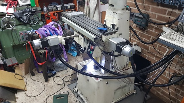 20210628_195317 20210628_195317 by Georgia Montgomery, on Flickr Propping the knee up high makes it easy to wind the leadscrew down.  20210628_201132 20210628_201132 by Georgia Montgomery, on Flickr This plate clamps the bearing outers against the bottom of the pocket, but the fit was a bit tight. Here I'm adding a little clearance, and also making the relief 0.3mm deeper in case that's preventing the bearings from being clamped.  20210628_204600 20210628_204600 by Georgia Montgomery, on Flickr The E220 7CE1 DUL bearings are the right way round, back to back, with the runout markings aligned. It might have been better to have Medium preload instead of the universal light. 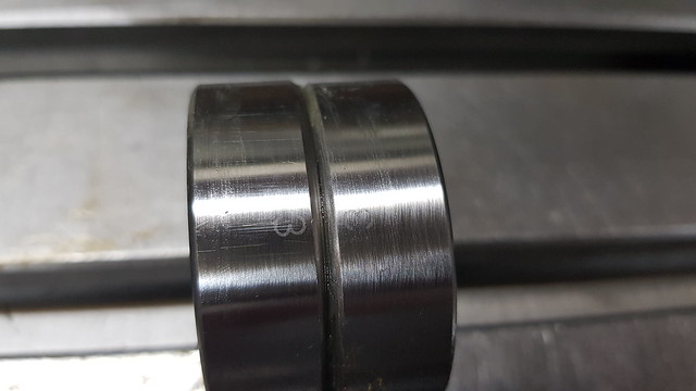 20210628_205018 20210628_205018 by Georgia Montgomery, on Flickr I also checked to make sure that the bearing inners were properly clamped with the nut.  20210628_211253 20210628_211253 by Georgia Montgomery, on Flickr Anyway, that made no discernable difference, so I concluded that I just didn't understand what the graph was telling me. All I've done here is to increase the maximum allowable outputs that the drive can provide to the Servo, and that's fixed the issue. Now you can see that the middle of the travel settles down to a small error after the initial large spike. However, that spike is pretty large, so I've posted the relevant information to the KMotionCNC forum in the hope that they can figure out how to make this better.  Z-axis error response Z-axis error response by Georgia Montgomery, on Flickr To be honest, I don't really understand why this seems to think there's a huge error. There's a 2:1 reduction on the leadscrew drive, and that means that 4 steps represent 1 micron. By my calculations, I interpret the scale reading of 1200 to be 1200/4=300microns, which seems a lot. Anyway, I'll wait and see what the expert who designed this system has to say. If you didn't have these graphs, you'd assume it was spot on. It moves smoothly and it's snappy when commanded to move. |
|
|
|
Post by Roger on Jun 29, 2021 16:53:56 GMT
I still need to get back to the tuning and lost motion issues, but I also needed to get the Spindle to work. To that end, I wired it all up and managed to figure out what DAC channel would work as per the instructions here. They're pretty comprehensive, but there are a few curved balls to catch you out. Once you've got it working using the KMotion setup program, what it doesn't make clear is that you need to copy all of the Configuration parameters in the Initialisation.c file and paste them to create a whole new secion for the Spindle. You have to renumber the channel for each of the parameters and make sure the final line tells it to enable the correct channel number. Once this has been done, the parameters will be wrong of course, because you've copied them from another channel. However, when you press the appropriate button in the Configuration window, it then includes those parameters in the ones it's copied from the dialog boxes to the 'C' file. See what I mean? It's not complicated, and it's logical, but it certainly isn't obvious. Anyway, here's the initial reworking of the screen layout, less the 3 digit resolution DROs which I'll sort later. The original screen had the large jog arrow buttons moving the axes rapidly, and the smallest ones doing the step moves. That might suit some users, but it's an accident waiting to happen if you're jogging using a centre finder. So in the layout below, the big arrows step the amount shown in the radio buttons. I've hidden the one that moved 10mm, again, that's an accident waiting to happen. The idea is that the Red buttons are a rapid continuous move, the Orange buttons are a slow continuous move, and I can be a bit less accurate with the mouse when I'm jogging small increments to find an edge. I've also removed the Inch/Metric and Inc/Abs Radio buttons because I'm never going to use them, and it's easy to end up in the wrong mode. I've separated the Z and A axes away from the X/Y ones to make it clearer which is which and avoid accidentally clicking the wrong ones. The Home button is one I've implemented, and that calls the much modified multi axis homing program that had several bugs in it. That works a treat, and so do the soft limits now I've arranged it so you can home it with those disabled. I don't think anyone can have used the supplied program the way it's intended, it just doesn't work as written. The homing sequence immediately went into soft limits when attempting to home, because they were enabled even before homing had been done. I just temporarily overwrite the values to be huge in both directions while homing, and put them back as they were when it's done. Simple but effective. I'm sure there will be other changes, but it's a good starting point. It's going to take quite a bit of getting used to, but at least it's completely configurable, and I can change pretty much anything if I put my mind to it! 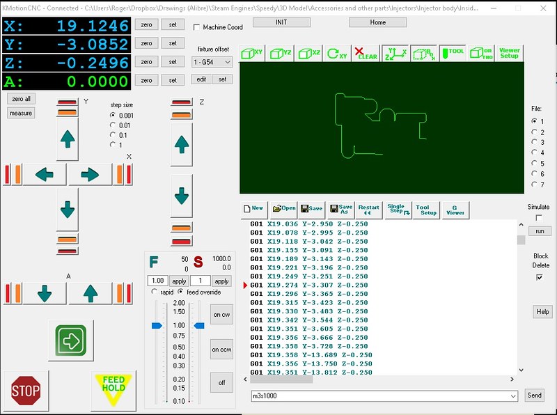 Screen setup Screen setup by Georgia Montgomery, on Flickr |
|
|
|
Post by Roger on Jun 29, 2021 21:27:26 GMT
Ok, back to tuning and hunting down lost motion on the Z-axis. Here I've parked the knee down near the bottom so I can get a lever between the knee and the base casting. The machine is turned off, and the DC Brake is holding the Z-axis motor and the pulley via the toothed belt. Levering pretty hard, I can get about 60microns movement. I moved the clock to the other side of the column and found the results to be the sae, so it's not tipping over. So the conclusion is that this is nowhere near the 0.3mm I'm looking for.  20210629_210308 20210629_210308 by Georgia Montgomery, on Flickr This is the setup with the lever and a new extension I made for the 1micron Digital plunger clock.  20210629_210025 20210629_210025 by Georgia Montgomery, on Flickr Here I'm checking to see is the flexing I'm seeing is between the top of the leadscrew and the Y-axis carriage. That very nearly matches what I'm seeing overall...  20210629_210016 20210629_210016 by Georgia Montgomery, on Flickr ... however, this shows very little movement compared to the column. So the conclusion is that there's next to no lost motion in the ball nut at the bottom, but there's about 60microns in the region of the thrust housing. That's going to be comprised of the flex in the thrust bearings themselves and the flexing of the mount. That doesn't surprise me really, it could use some more meat around it. However, that's not easy to achieve because there's so little room around there. I would be happier if these figures were smaller, but at the moment I don't think there's a viable solution. It's not ideal, but I can probably live with it. It will certainly be better than it was before in any case. 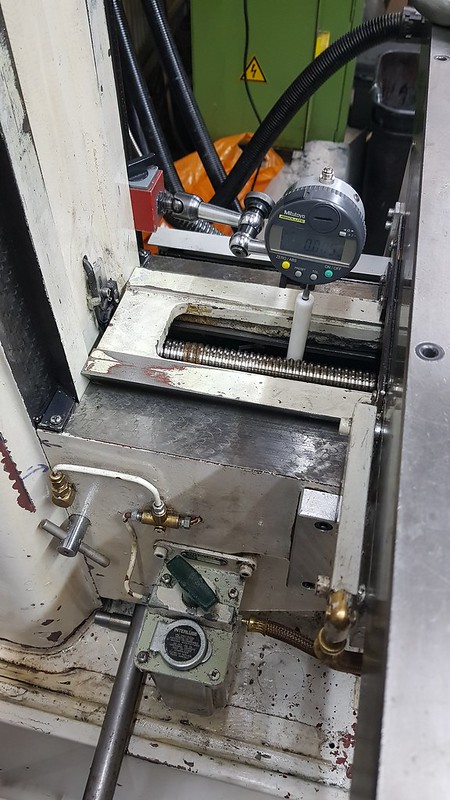 20210629_210643 20210629_210643 by Georgia Montgomery, on Flickr Anyway, the takeaway from all this is that I can't account for the errors that the graph is showing me, and so I need to look elsewhere. So, going back to basics, I've returned to the control loop, in particular the Z-axis Servo. If you recall, there's a position control loop that tries to close the angular position of the Servo Motor Encoder with the commanded position. To help see how good this performs, there's a mode you can select for the front display that shows that error in realtime. I used it on the X & Y, but for some reason failed to do so on the Z-axis. Anyway, here's how that looks in a wobbly video...  20210629_214535 20210629_214535 by Georgia Montgomery, on Flickr The third one along is the Z-axis, and you can see that the figures are huge when it moves. For comparison, the X and Y figures as mostly single digit values! So, this is the root of the lost motion I'm seeing on the graph, I need to revisit the Z-axis tuning and see where that's gone astray. I'll get this figure down to a sensible value and then see where that takes me. I've been tripped up by another curved ball when it comes to making these Step moves. I couldn't understand why they were initially cut short on the first motion, and that the graph then showed an offset. It turns out that the Soft Limits are again causing difficulties. The software is running into the +ve one after the initial boot, and those need to be temporarily overwritten to get it to work as expected. Again, it's logical, but not mentioned anywhere in the documentation or video. |
|
dscott
Elder Statesman
  
Posts: 2,440
|
Post by dscott on Jun 30, 2021 1:13:30 GMT
Nearly all looking good Roger.
In between other projects and the ODD CLUB RUN, We have been busy preparing our Mill for a belt conversion.
Polly v pulleys are hard to find so I went for 5 M X 15 mm Cogged timing belt instead.
We have one driving the electric Beast. Sorry 2 one in each unit. So they work well.
The head of the spindle is 55 mm so some turning of Pilot Bores will be needed.
Must make sure that all milling has been done prior to taking apart.
The extractor fan currently sat on top of the motor is keeping it cool, the extra big holes at the base help with airflow.
And AND the head does not get hot as it seemed to be in use as a heatsink for the motor.
Such a shame that Warco do not seem to be able to send round warnings of problems with some of their machines?
It was an after thought that the boss mentioned that others had fitted fans on the phone.
Plus I got rid of the HOT BOX with hardly any ventilation!
PS Warco/Unipart seem to have plenty of spares for Motors and plastic gears that easily strip their teeth.
David and Lily.
PS 2 The Dore Westbury sank its teeth into a 10 mm hole for a double bender used for Smokebox hinges today.
40 years not out.
|
|
|
|
Post by Roger on Jun 30, 2021 22:58:39 GMT
I've spent a bruising day, beating my head against the tuning issues with the SureServo AC Servo amplifiers. I tried my best to use the Autotune and Easytune modes, to no avail. They are neither Automatic or Easy, and the tuning results are hopeless. So it was back to carefully exploring the various gains to get the smallest possible following error while maintaining a tight response without resonance. All that is done open loop, running back and forth at speed. Once that was satisfactory, the loop was closed with the KFLOP controller, and the same tests had to be repeated, easing back on the parameters just enough to stop it complaining. It's all pretty tight, but then it has to be if it's going to maintain a path that's as close as possible to that commanded. Anyway, it's close enough to be usable now, so here is a wobbly video of it running a 3D parallel finishing pass at 2x the feedrate to see how it performs. It's probably a little too tight, you can hear it groan slightly from time to time.  20210630_233534 20210630_233534 by Georgia Montgomery, on Flickr There are immediately things that need attending to, such as stopping and restarting the spindle during a pause or feed hold. Other than that, I just need to buckle down and learn how to use it. I've probably got a job for it on Monday, so I need to get to grips with it. I can see that I'll need to delve into the software and fix some irritating issues. One of those is that it complains that it doesn't know whether it's Inch or Metric and the position of the A-axis when starting part way through a program. Not every program is going to have an A-axis command, and everything will always be Metric. For the moment I can add a line at the start of a program to fix that, but it really needs to be within the controller. All good fun. |
|
|
|
Post by Roger on Jul 4, 2021 20:48:03 GMT
I've finally managed to compile the Open Source C++ KMotionCNC project with a few changes that make it more to my taste. There are still some things I need to sort out, such as a delay for the spindle to reach speed before moving off. I can't see how that can be done at the moment, because the motion control and the spindle controls are running in separate threads. If I add a delay after turning on the spindle, it's only a delay in that function returning! Anyway, I've asked the question, so hopefully it's a simple thing to add. However, in the meantime, here's a screenshot showing two of the changes I've made. The first is that it now displays three decimal places when in Metric mode. If a program switches it to Imperial, it shows them as four places. I had a brainwave to help me during my usual setup technique which is to use an edge finder on one side, zero the DRO and then use the edge finder on the other edge. Than I use a calculator to halve the DRO setting and type that back in. So what I've done is to modify the behaviour of the Set Value dialog box which is common to many functions. You can pass a label and value string to the dialog box when it's created, so I send it 'Set DRO' and the value I want seeded in the box when that's present. So all I've done is to keep track of what value is currently in the DROs, and then I halve it and present that as the default value to enter. Here, I've pressed the 'set' button next to the X-axis DRO, so the Set value showing is half 24.758 ie 12.379. All I have to do is click Set on the dialog box, and there's no calculation or remembering which side I found first. Simple, and the result is that the DRO ends up in the centre of the work. It's only the same as typing that value there, so you can still enter any value you like if that's not what you want to do. The default is normally either zero, if you haven't entered anything before, or the last one out of a list. You can see that it's a drop down box, and that still works, showing the previous Set value, whether that's my half value or anything else. Yeah, I know it's not a big deal, but it's something I do all the time, and I'll get a little kick of pleasure every time I use it. This is where KMotionCNC really scores over Mach4. You have complete access to the source code, so you don't have to be a victim of whatever the developer sees fit to change, whether you want it changed or not. If you're not a programmer, you'd probably find this impenetrable. It's cleverly written code and it's far from obvious how things hang together until you've beaten your head against it for a few hours. Still, I find it interesting, and ultimately I get what I want from it.  KMotionCNC set value KMotionCNC set value by Georgia Montgomery, on Flickr |
|
|
|
Post by Roger on Jul 13, 2021 22:46:49 GMT
I've spent the day machining a large 304 Stainless piece for a customer, and it all seems to be behaving. There are still a few issues to resolve with the logic of the way the Spindles start. Implementing a delay for it to ramp up isn't as easy as I thought it would be. The Software Engineer on the Forum is pretty helpful, but has a tendency to be a bit abrupt and provides half answers and hints rather than explaining clearly how to go about things. I think he's bored with it, and knows it so well that he assumes it's obvious to other too. It isn't.
Anyway, I'll figure it out one way or the other, even if he get the hump from my last reply! I'm not lazy, and I don't expect to be spoon fed. However, I'm not a mind reader eiher!
Delving into the code and recompiling the whole KMotionCNC project in Visual C++ has given me a much better insight as to how things work. It's taken a lot of time and effort to get this far, but I think it's been worth it.
Hopefully I'll be able to move on with 1501 again shortly.
|
|
|
|
Post by doubletop on Jul 17, 2021 2:33:12 GMT
 Z-axis error response Z-axis error response by Georgia Montgomery, on Flickr To be honest, I don't really understand why this seems to think there's a huge error. There's a 2:1 reduction on the leadscrew drive, and that means that 4 steps represent 1 micron. By my calculations, I interpret the scale reading of 1200 to be 1200/4=300microns, which seems a lot. Anyway, I'll wait and see what the expert who designed this system has to say. If you didn't have these graphs, you'd assume it was spot on. It moves smoothly and it's snappy when commanded to move. Roger I've just had a skim through your thread to see if you've resolved this issue or decided to just live with it. Although you've been looking for backlash my immeadiate thoughts were inertia or latency. Intertia as the Z axis is way heavier than the X or Y axis and latency in any timimg difference between the control input from the software and the read of the DRO's. I'd suspect you've done this but running the test really slowly may give some different results and maybea hint. Do you have one of those cheap logic analysers to be able to check the I/O timing. www.dreamsourcelab.com/ or www.ebay.com/itm/161309241759 I have both, they do the job and use variants of the sigrok open-source signal analysis software Pete |
|
|
|
Post by Roger on Jul 17, 2021 7:35:46 GMT
Hi Pete,
I don't have a logic analyser, but I've used one in the past and they're certainly useful. One day I'll treat myself to one, they're not that expensive realy. I could use to replace my old Textronix scopes too.
Fortunately, the KMOTION software does a pretty good job at capturing the detail of what's going on. It's based on a DSP, so it's got the power to do that.
The huge error in the Z-axis turned out to be a tuning issue with the AC Servo having a huge following error. I'd used the same parameters as the X & Y and it seemed to work ok, but the Z-axis dynamic needed very different settings. Tuning the AC Servos is very difficult if you want to get the best out of them. You go round in circles, experimenting with the different gains and filters to home in on the tightest possible response without oscillation. If you don't do that, the following error on the motion controller is too large under high accelleration.
The current state of play is that I've implemented the Anti-Dithering code in the motion controller and that's really helped it stabilise at the target point, but there's still room for improvement. The issue, as always, is with lost motion, which is about 11microns on the X & Y. Classical control solutions don't account for non-linearity, so I need to experiment with some code to give a non-linear response to take up the slack when reversing direction. Fortunately, the motion controller allows you to add any code you like in the endless loop that runs in the initilisation thread. That runs in parallel with the main control loops, and lets you modify the reponse at any time you like.
You're absolutely right about running it slowly giving a different response. The lost motion is much more problematical at slow speeds.
KFLOP does implement backlash compensation for use in open loop systems, and they supply you with the code they use for that. It's not intended to be used in closed loop systems like mine with Linear Encoders. However, I swhould be able to use that as the starting point for some experiments. This is where this system really comes into its own. Being able to modify every part of it is a welcome change from Mach4, where you get what you're given and it's only open loop.
|
|
|
|
Post by doubletop on Jul 18, 2021 5:02:41 GMT
Roger
I becoming interested in what you are up to, been on the Dynomotion website to check out the products and signed up for the forum. Although I'm capable of dealing with the software the only problem I see is the possibility that maintaining the software takes over from the main objective of getting CNC running. I'm of an age that means I forget what I learned last week and have to go and find the references again to remind me what I'd done last time. Then there's the situation where there is a major release upgrade and all the items from your own fork have to be included and re-tested. Maybe a step too far.
Shell out for one of the 10quid logic analysers from Hobby Components, or add it to your Christmas list. You'll wonder why you hadn't done it earlier.
Regards
Pete
|
|
|
|
Post by Roger on Jul 18, 2021 8:28:25 GMT
It's certainly not trivial to get under the skin of this product. If you look at the summary I put about that in this thread, you'll see what I mean. Tom Kekeres who answers all of these questions in the Forum is the author of all the software as far as I can tell, and possibly the hardware too. He's a big crusty and short in some of his replies, which can be annoying. He's also prone to give half answers that still leave you figuring out a lot for yourself. However, with a bit of patience, and biting your tongue, you can get what you need. I made life more difficult for myself by being determined to use the Step & Direction interface to the SureServo AC drives. I dislike Analog solutions for things like this, I've seen too many runaways for my liking, and that's not going to happen with a digital interface. That did involve making my own PCB to use the auxiliary alternative outputs for these functions, and getting the information on how to make that work was a bit painful. However, having gone through all of this, and knowing how it all hangs together, I rather like the configurability. I've made quite a few changes to the KMotionCNC open source project, but those are pretty much all in one file. I installed the whole package in my Dropbox folder, so any changes are immediately backed up and revisions kept. I've also made copious notes on how to do things, my memory sounds like yours. I'm probably going to have a day experimenting with ways to improve the stability and accuracy when it's stationary by implementing a backlash modifier in the init.c endless loop. You can modify the servo characteristics in real time, something you just can't do with other systems I've looked at. If you're just looking to plug something in and get it working in a day, then this isn't for you. However, if you do take the time, you will finally be in control of your own destiny. Updates are very few and far between, because Dynomotion are really selling the KFLOP and the interface boards which are intended for commercial end products as an OEM part. They give you KMotionCNC as open source, probably as a demonstrator and hobby interface. I can't see a serious machine tool manufacturer using it. It's a bit clunky, more Mach3 than Mach4 when you modify the screen, but not as painful as Mach3. Anyway, hopefully that gives you a flavour of what the product is all about. Cheers, Roger |
|
|
|
Post by doubletop on Jul 18, 2021 21:21:13 GMT
Roger What drew my attention to this is being able to utilise the DRO's to close the feedback loop. I'd always thought that an open loop system was questionable. Although I've been on the periphery of others CNC conversions I do really need to get some details together to do my mill. Starting with ball screws and then determining what type and size type of steppers to use. I wasn't aware of AC drives. A question comes to mind about the integration of motor step counts and DRO readings. Does the system read the DRO's after every step and recalculate the steps to go? Does that have any effect on overall system speed? For example, to do a fast/long move stepper counts should suffice to get 'there abouts' however, you can't afford to overrun as there is no going back if the cutter is into the job. So when do the DRO's come into play? Maybe the antidithering has some role to play here? Anyway if I do eventually decide to go ahead I know where to come for the additional interface boards, because you never get custom PCB's made as a one off   Pete |
|