johan
Seasoned Member

Posts: 118
|
Post by johan on Jun 11, 2024 19:57:25 GMT
I'm (slowly) drawing my project and at the same time evaluating each part on how I would be able to make it. Right now I have arrived at the engine part. And I come to the conclusion that I do not have enough vertical travel on my mill to bore things like cylinders, cylinder sleeves, tunnels for the crankshaft etc. My mill spindle only has 50mm travel vertically and that is not enough. And moving the complete head won't be very stable.
I do have a 4 claw but the engine case is just too large to hold or swing (if I could clamp it in). I also have a V-block but even my largest boring tool will not cut 130mm deep. So it looks like a boring bar between centers is the only solution left. But then I have the problem that I do not have the possibility to attach something to the saddle. The saddle on my lathe is just equipped to take a cutting tool holder.
Apart from getting new (larger?) mill or lathe (*) I was thinking about fixing a T-slot plate to the saddle of the lathe. Has anybody here experience with doing that? Would an alu T-slot plate enough or should it be (cast) iron? Is it a reasonable idea or are there better ideas?
(*) just getting a new lathe for a few components looks a bit silly. And then we are not even considering the space needed or -worse- price.
|
|
uuu
Elder Statesman
   your message here...
Posts: 2,858
|
Post by uuu on Jun 11, 2024 20:38:46 GMT
Drilling some holes in the cross-slide and tapping a thread in them might work for clamping your part, and be less effort than a tee-slot plate.
Wilf
|
|
johan
Seasoned Member

Posts: 118
|
Post by johan on Jun 11, 2024 21:05:06 GMT
Good idea. I would have to drill the top anyway to fix a T-slot plate so I could indeed just do that. I'll have to look how thick that top of the cross-slide is. And how to take it off...
|
|
SteveW
Elder Statesman
  
Posts: 1,456
|
Post by SteveW on Jun 12, 2024 11:12:12 GMT
Johan,
Have you considered using your mill to carve four, suitably spaced, reference pads on your lathe cross slide or perhaps saddle and adding tapped holes to secure a 'T' slot or similar plate or fixing?
Agreed, it does seem a bit brutal but would a whole load of usefulness to your lathe.
|
|
|
|
Post by GWR 101 on Jun 12, 2024 13:29:49 GMT
Unless I have missed something, I do not see any mention of the make of lathe. Paul
|
|
johan
Seasoned Member

Posts: 118
|
Post by johan on Jun 12, 2024 14:16:31 GMT
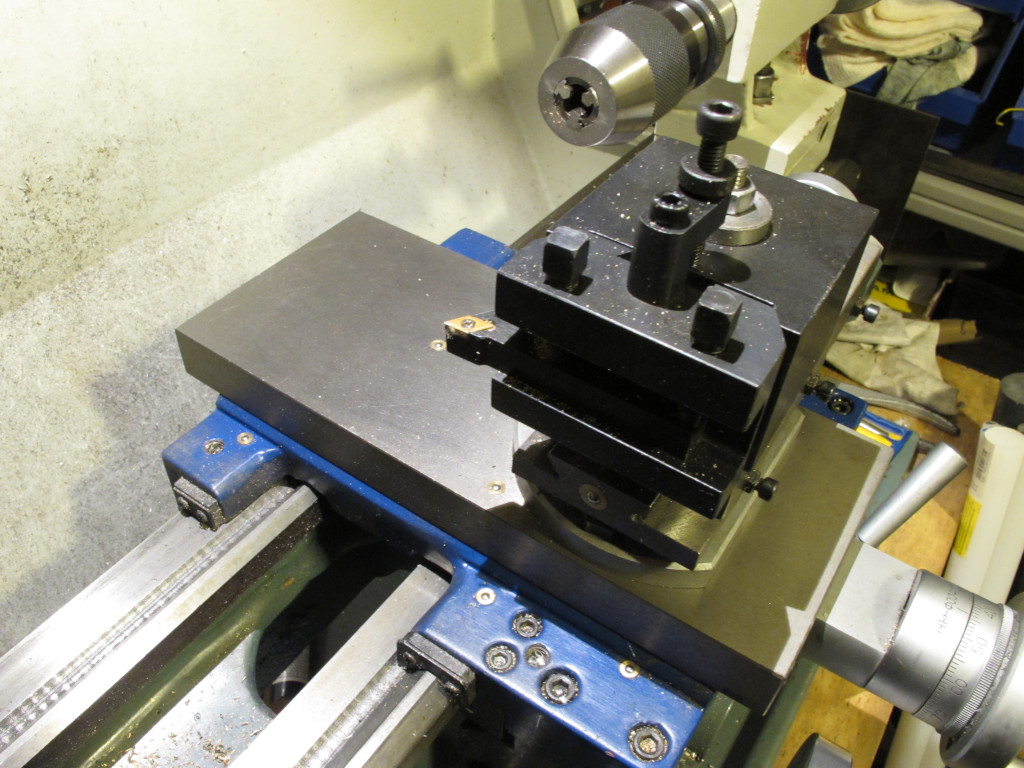
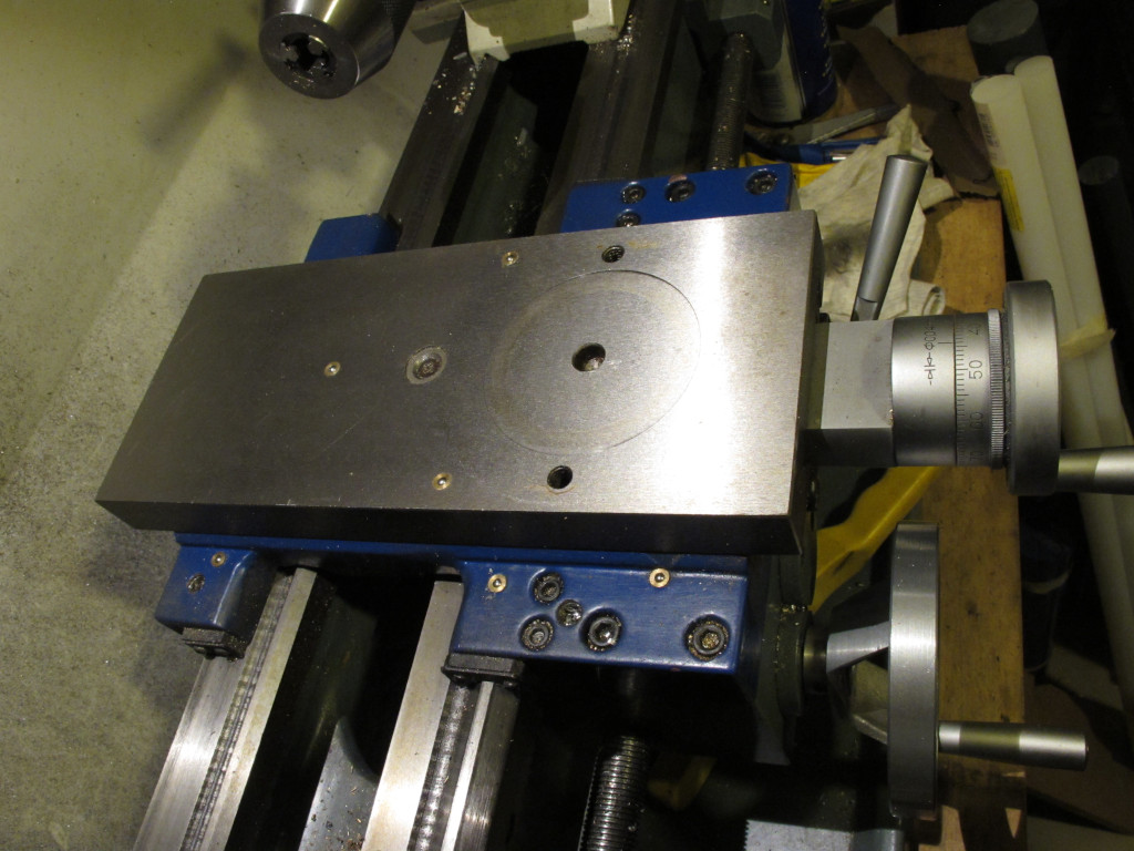
It looks that I mixed up "saddle" and "cross slide". I would like to have those T-slots on the cross-slide Johan, Have you considered using your mill to carve four, suitably spaced, reference pads on your lathe cross slide or perhaps saddle and adding tapped holes to secure a 'T' slot or similar plate or fixing? Agreed, it does seem a bit brutal but would a whole load of usefulness to your lathe. I thought of something along those lines. Only I have not really an idea on how to exactly do it. I'm afraid of weakening the cross-slide or worse messing up the lathe. Also I'm not sure if I should just put a piece of T-slot plate over the cross slide and attach the compound slide to that OR each time swap the T-slot plate and compound slide. Unless I have missed something, I do not see any mention of the make of lathe. Paul You have not missed it. It is a "HBM CQ6125x400". HBM is a dutch machine shop, very popular with hobby users and they have a range of branded machines. CQ6125x400 lathes were/are sold under a number of brands, only the color scheme changing. Mine is blueish grey/blue accents but you could find then pale grey/purple, green/yellow etc. All the same machines. Some versions (newer ones) do have a cross-slide with two T-slots but sadly mine hasn't. I added a few photos.   Now I seem to have 4 options: 1: put in a few more threaded holes like the ones that hold the compound slide and use these to attach something directly to the cross-slide 2: put in a few more threaded holes like the ones that hold the compound slide behind the compound and put a short piece of T-slot plate (2 slots I guess) 3: put in a few more threaded holes like the ones that hold the compound slide, remove the compound and put a piece of T-slot plate (2 slots I guess) over the whole of the cross-slide (swapping each time plate and rest) 4: put in a few more threaded holes like the ones that hold the compound slide, remove the compound and put a piece of T-slot plate (2 slots I guess) over the whole of the cross-slide and mount the compound to this plate (if I can still get my tools at the right height) |
|
johnd
Part of the e-furniture

Posts: 298 
|
Post by johnd on Jun 12, 2024 14:34:39 GMT
Could you possibly bolt and angle plate to your bare cross slide using the toolpost bolt. A bar bolted to the underside of the angle plate resting against the front face cross slide would resist any twisting motion. The angle plate vertical surface would then be able to hold your block using long bolts and cross bars.
|
|
johan
Seasoned Member

Posts: 118
|
Post by johan on Jun 12, 2024 17:17:35 GMT
Could you possibly bolt and angle plate to your bare cross slide using the toolpost bolt. A bar bolted to the underside of the angle plate resting against the front face cross slide would resist any twisting motion. The angle plate vertical surface would then be able to hold your block using long bolts and cross bars. Possibly. But I don't see how I would be able to get the part at the right height in that case. Or at least not how to do it for easy adjust of the height. |
|
johnd
Part of the e-furniture

Posts: 298 
|
Post by johnd on Jun 12, 2024 18:00:02 GMT
I have bored cylinders bolted both on the cross slide and on an angle plate mounted on the cross slide, the setup method is the basically the same for both.
To set hight use toolmakers button on bore face then used dial gauge mounted in lathe chuck to dial in button using packing under cylinder to get correct height.
Use drills then a between centres boring bar to finish to size.
The only reason to prefer the angle plate is that there would be no need for cross slide modification.
|
|
johan
Seasoned Member

Posts: 118
|
Post by johan on Jun 16, 2024 14:47:50 GMT
I have decided to start by putting some extra threaded holes in the top plate. Same and in line with the holes for the compound. But how to take off the top plate and at the same time dismantle as little as possible? I have been looking at it but this is not really my forte.
I can not just turn the spindle of the cross-slide long enough to slide it off at the back because I would need to remove the drip plate at the back. And I don't see how to do that, it looks welded to the bottom drip plate. So unless taking everything apart that looks not the way to go.
If I see if well, then I could release the bolts that adjust the gib and then slide the gib out to the front. Next remove the screw that holds the nut of the spindle and the handwheel. And I think that I can then slide the top plate off to the front.
Does anybody foresee issues when doing that?
|
|
SteveW
Elder Statesman
  
Posts: 1,456
|
Post by SteveW on Jun 19, 2024 11:16:14 GMT
Johan,
Maybe add a few more detailed photos of your cross slide both from front and back.
Bottom line being someone got it on there so someone should be able to get it off.
Have you tried unscrewing the cross slide dial assembly and screwing it out completely? From the images above it looks like the dial stays with the saddle and the cross slide and not the dial moves. This would suggest the slide has a big peg underneath with the cross slide nut. The hope would be this peg runs in a channel full width of travel and can be slide off once the lead screw is gone.
Maybe with the gib strips out the slide might just lift off, perhaps just needing a bit of a wiggle.
|
|
johan
Seasoned Member

Posts: 118
|
Post by johan on Jun 19, 2024 18:10:23 GMT
Bottom line being someone got it on there so someone should be able to get it off. Very likely. Even if it involves a large hammer, a crowbar and an angle grinder. But I'm not very gifted for this kind of stuff and I really want to end up with a usable lathe. So I prefer asking twice. That is probably the way is is. The dial and handwheel sit on a piece that is screwed into the apron. And there is a large screw in the middle of the cross-slide that probably hold the cross slide nut when I look at it. Only thing I'm unsure about is how the spindle of the cross slide is held at the far end of the handwheel. Can't make that out. I'll have to risk it this weekend. Undo the screw that likely holds the cross slide nut, remove the gib (it will have to come off anyway) and then see if I can lift it. If I can not then remove the screws that hold the handwheel/dial and see where I get. |
|
SteveW
Elder Statesman
  
Posts: 1,456
|
Post by SteveW on Jun 19, 2024 21:53:09 GMT
Only thing I'm unsure about is how the spindle of the cross slide is held at the far end of the handwheel. Can't make that out. As a guess I'd say the far end of the cross slide lead screw won't have any support other than the cross slide nut. |
|