redmog
Part of the e-furniture
 Not Morgan weather
Posts: 461 
|
Post by redmog on Aug 11, 2009 11:07:10 GMT
Must Be Fixed.
Hello Ace,
Yes - mine's a very tight fit on the pin, which has allowed me to set and test the valve timing,
but for my purpose it must be 'Fixed'
I wouldn't want it moving when I'm half way round the track!
Chris
|
|
|
|
Post by baggo on Aug 11, 2009 11:13:00 GMT
Hi Chris, When I made the return cranks for Helen I reamed the hole for the crankpin to a good tight fit before cutting the slot. They are also clamped with a 10BA bolt but this doesn't have to be really tight. Once the return crank position was set I drilled for a 1/16" silver steel pin half in the crankpin and half in the return crank (just like pinning a wheel to an axle). They'll never move! John  |
|
redmog
Part of the e-furniture
Not Morgan weather
Posts: 461
|
Post by redmog on Aug 11, 2009 18:44:43 GMT
Return Crank to be Pinned.
Thanks John,
I think that's the best method.
I only wish now that I hadn't cut through to the opposite side of the hole with the slitting saw.
I did it with the hope of a little more flexibility for closing the hole with the screw.
It'll have to go at 90 degrees not 180.
Chris
|
|
redmog
Part of the e-furniture
Not Morgan weather
Posts: 461
|
Post by redmog on Aug 13, 2009 17:44:55 GMT
Return Crank Pinned. I knew I had some 3/64" silver steel somewhere. threw it under the bench some 20 odd years ago. Well it's come in useful for pinning the Return Crank al - a - Baggo style. The drill wanted to wander towards the least dense direction, but it's turned out OK. Valves open spot on TDC and BDC - but should they? Is there any theory about whether they should open before or after DC. Chris 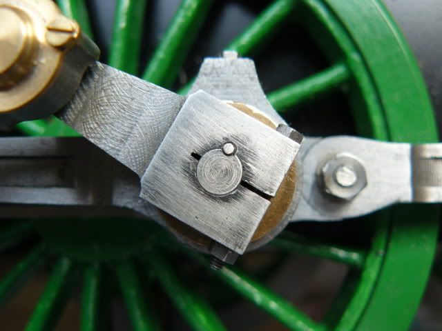
|
|
redmog
Part of the e-furniture
Not Morgan weather
Posts: 461
|
Post by redmog on Aug 13, 2009 17:55:43 GMT
What Difference?
Another thing I have noticed is that the Return Crank 'leads'
the crankpin.
On my B1 it 'follows' the crankpin.
Can the more knowledgeable explain why?
Chris
|
|
simonwass
Part of the e-furniture
Cecil Pagets 2-6-2 of 1908. Engine number 2299. Would make a fascinating model....
Posts: 472
|
Post by simonwass on Aug 13, 2009 18:22:53 GMT
Inside and outside admission, usually piston and slide valves respectively. You can get outside admission piston valves though.
Inside admission for trailing return crank ie it leans forward, I think this arrangement looks neater.
|
|
|
|
Post by baggo on Aug 13, 2009 23:35:07 GMT
Valves open spot on TDC and BDC - but should they? Is there any theory about whether they should open before or after BC. It depends whether the valve gear has been designed to give 'lead' or not, lead being the amount the ports are open at front and back centres. LBSC was a firm believer in following full size practice if possible and usually, if not always, designed his gears to give lead i.e. the ports open very slightly before dead centres. When the piston is at front or back dead centre the port would appear as a thin black line at the end of the valve. With Walschaert's gear (as used on the V4), the amount of valve travel in mid gear is controlled by the combination lever and should be equal to twice the lead plus twice the lap of the valve. With other gears, such as Stephenson's, the lead varies with the cut off. I haven't got the details of the V4 valve gear so can't tell you what the lead should be without seeing the drawings. I've analysed a few designs with Walshaert's gear and the lead seems to range from 10 thou up to 30 thou. John |
|
redmog
Part of the e-furniture
Not Morgan weather
Posts: 461
|
Post by redmog on Aug 14, 2009 20:56:37 GMT
A Milestone. Valve gear complete, I think! It should soon be ready for testing on air. I need to make up the inlet manifold and an adapter so that I can connect it up. Connect it up to what? I don't have a compressor. Any suggestions. John - Thanks for the reply. I'm still digesting it. I looked at the valve opening again today. It's hard to measure the TDC positioning but the valve opens swiftly during the 'dwell'. 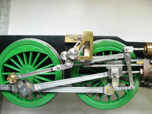
|
|
redmog
Part of the e-furniture
Not Morgan weather
Posts: 461
|
Post by redmog on Aug 31, 2009 19:04:32 GMT
Making a Tube Elbow. Advice Please. What is the purpose of this tube that runs from the cab to the smokebox, half way up on the exterior of the boiler, on full size locos? It's time I did a bit on the B1's platework to make her look more complete, and intend making up this tube. I am open to recommendation for the making of the elbow from the more experienced. Thanks for any advice. Chris 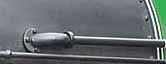
|
|
simonwass
Part of the e-furniture
Cecil Pagets 2-6-2 of 1908. Engine number 2299. Would make a fascinating model....
Posts: 472
|
Post by simonwass on Aug 31, 2009 19:58:48 GMT
Steam ejector exhaust.
Steam ejectors on LNER locos were combined units in the cab, they were the ejector and associated valves in one lump, dreadnaughts I think they were called.
|
|
steam4ian
Elder Statesman
 One good turn deserves another
Posts: 2,069
|
Post by steam4ian on Aug 31, 2009 21:28:34 GMT
G'day Chris That particular pipe and elbow looks like the exhaust for the vacuum brake ejector. You will note that it is on the driver's side. (Edit missread Simon's post  ) The steam lines for exhaust steam injectors I have seen are much larger, lagged and run under the valance/running board. You would need more steam than the pipe in the photo could carry. I must admit my experience is limited to the WAGR W class with vacuum brakes and the SAR 520 class with exhaust steam injectors (Davies and Metcalfe). Regards Ian |
|
JDEng
Part of the e-furniture
Posts: 384
|
Post by JDEng on Sept 1, 2009 18:22:49 GMT
Both the previous posts are correct, it's the exhaust pipe from the Combined Vacuum Ejector/Brake Valve; these were made by Davies & Metcalf I think and the LNER types were generally of the Dreadnought type as opposed to other available models.
On the full size the elbow is normally a casting: it's flanged to the smoke-box and the pipe connection is by way of a union the nut of which is slotted for a 'C' spanner as opposed to being hexagonal.
Might it be possible to make one up from a Wade or similar compression fitting with a bit of work with a file to "pretty it up" and make it look scale? I presume it's not going to be a working pipe?
Hope this helps.
Regards.
John.
|
|
|
|
Post by GeorgeRay on Sept 1, 2009 18:34:16 GMT
I think you'll find that Dreadnought ejectors were a Gresham and Craven design.  |
|
JDEng
Part of the e-furniture
Posts: 384
|
Post by JDEng on Sept 2, 2009 17:20:47 GMT
I think you'll find that Dreadnought ejectors were a Gresham and Craven design. Fair comment, I wasn't dead sure. Davies and Metcalf did make a similar combined ejector/brake valve but it obviously wasn't sold as the "Dreadnought". Cheers. John. |
|
redmog
Part of the e-furniture
Not Morgan weather
Posts: 461
|
Post by redmog on Sept 21, 2009 19:29:39 GMT
Good Photos JB. Nice work JB. I wish you luck with the barrel. When is a circle not a circle? I've made a start on my boiler so please get it right JB. because - I'm following in your footsteps of good practice. Chris 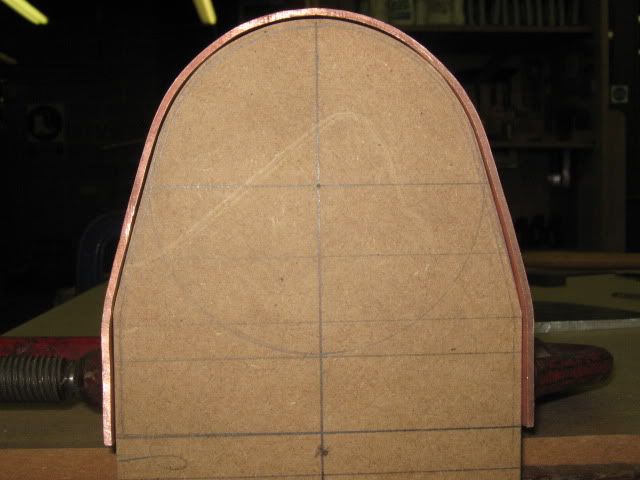
|
|
|
|
Post by Deleted on Sept 21, 2009 19:39:00 GMT
Hi Chris.
Ooh! I'm not sure I want that responsibility at my stage of life! Is that a solid former? It's a perfect fit.
Down at the club they told me to make one but I just muddled through without one!
JB
|
|
redmog
Part of the e-furniture
Not Morgan weather
Posts: 461
|
Post by redmog on Sept 21, 2009 20:04:42 GMT
Fore and Aft.
No JB.
Two identical formers made from 25mm MDF.
Keeps both ends in shape so all is parallel and square.
I wouldn't want to be making a tapered fire grate next year.
Chris.
|
|
redmog
Part of the e-furniture
Not Morgan weather
Posts: 461
|
Post by redmog on Sept 21, 2009 20:36:46 GMT
Not Identical. Sorry - They are not identical. The front one sits on a base to keep faces square, and is about 40mm thick. The back one is over full depth and not attached, so that it can be held in the wood vice. 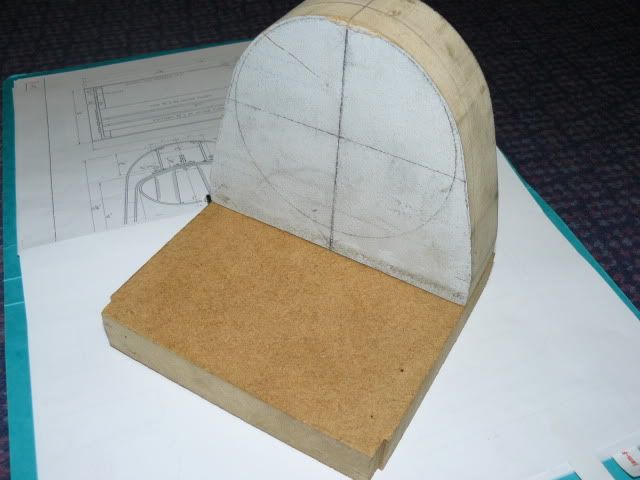 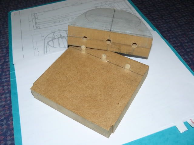
|
|
redmog
Part of the e-furniture
Not Morgan weather
Posts: 461
|
Post by redmog on Sept 23, 2009 20:35:35 GMT
More Advice Sort. You may be struggling to get tube of 4¼" Dia. You could always roll the barrel from sheet and fit a butt strap on the joint. John I've made a start on the firebox wrapper, but I'm thinking of starting again. I was thinking of taking Baggos advice as above and roll the barrel. Can anyone see a snag in making the firebox outer wrapper and barrel in one piece? OK, so it cannot be rolled, but - surely I can form the barrel section over a tube of the correct diameter. I would make up a cardboard template of the wrapper and barrel as one unit, then transfer the shape to the copper sheet. Bend it over a tube, then wrap the barrel until joining faces meet. Saves the joining process of the wrapper and barrel and everthing will stay in the same plane. Have I missed something? Chris 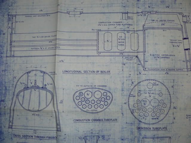
|
|
simonwass
Part of the e-furniture
Cecil Pagets 2-6-2 of 1908. Engine number 2299. Would make a fascinating model....
Posts: 472
|
Post by simonwass on Sept 23, 2009 23:15:08 GMT
I presume you mean the outer wrapper.
There is no issue making the barrel and firebox outer wrapper from one piece. If you are going to roll the barrel rather than use tube then its a no brainer, if you can get 4 1/4" tube then you can open out the firebox and extend one leg as the tube circumference isn't enough to make long enough firebox legs.
Making from one piece saves the pain to make & fit butt strip on the barrel to firebox join. I'd recommend making a flanged throatplate to barrel join but they are a pain to make with a sloping throatplate. A piece of 1/8" square in the corner is as good as anything, depends is you have room for lagging?
|
|


 )
)
