ace
Statesman

Posts: 528
|
Post by ace on Oct 3, 2009 23:41:26 GMT
A Flame Gulper
I am looking for plans to build a small flame gulper to present to a soon to be retired friend. I have looked online but couldn't find anything.
Anyone got any ideas or has someone built one that I could have copies of their plans.
most greatful
ace
|
|
jasonb
Elder Statesman

Posts: 1,293
|
Post by jasonb on Oct 4, 2009 6:34:12 GMT
Model Engineer had plans for one of Jan Ridders flame lickers, you can also get the plan straight from Jan. I think the plans are also on a few sites, just google Jan Ridders 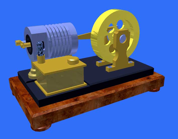 Jason |
|
tcase
Involved Member

Posts: 52
|
Post by tcase on Oct 4, 2009 10:31:27 GMT
|
|
ace
Statesman
Posts: 528
|
Post by ace on Oct 4, 2009 21:51:34 GMT
Many thanks guys, that's just what I was after knew someone on here could help.
ace
|
|
isc
Statesman
Posts: 708
|
Post by isc on Oct 5, 2009 12:28:16 GMT
Hi Ace,I built a Flame Gulper from a drawing in an artical in ME dated 17 April 1970,its called the Atkinson hot air engine,and the drawing is by Edgar T.Westbury.When first built it required a gas flame,and I had U shaped pieces of aluminium wedged in the fins for extra cooling area,it also required another flywheel to suppliment the one fitted,but now it runs on meths,the extra cooling is removed,and it only needs its one flywheel.It has a bore of 1" stroke1 1/2"(25mm x 38mm).isc psI'v just built one of Jan Ridders engines(as in photo above)but I havn't got it going yet.
|
|
|
|
Post by modeng2000 on Oct 5, 2009 15:03:56 GMT
Looking at Jan Rider's drawings, he dimensions some threads as M5x0.8-6H (internal thread) and M5x0.8-6g (external thread).
Can someone explain what the -6H and -6g mean please?
John
|
|
|
|
Post by havoc on Oct 5, 2009 15:55:01 GMT
|
|
|
|
Post by modeng2000 on Oct 5, 2009 18:09:01 GMT
Thanks Havoc, now I understand.
As far as I can see from the drawings the measurements are just for a thread, no locating section. I guess this is Jan being a perfectionist!
John
|
|
|
|
Post by havoc on Oct 5, 2009 18:55:45 GMT
Or tries to impress.
I looked at those plans and I'm inclined to belief he tries to impress. Why else put a tolerance indication on threads that have nothing more to do than hold the cilinder but no tolerance on the bore of the cilinder/piston. Or equally important the hole/pin of the conecting rod at the pîston side.
|
|
jackrae
Elder Statesman
Posts: 1,335
|
Post by jackrae on Oct 5, 2009 20:41:17 GMT
John,
Basically the tolerances are set so that the male part at maximum tolerance fits into the female part at minimum tolerance.
When I was at uni - more years ago than I care to mention - we did a course on manufacturing tolerances that was based upon fire-arms manufacture. Basic premis was that all parts would fit into any gun of the same model etc and most importantly would still work. At least it made for listening interest in the days when we were allowed to discuss such things without being branded as potential terrorists.
jack
|
|
|
|
Post by modeng2000 on Oct 6, 2009 6:23:24 GMT
Interesting times Jack, not something I have had dealings with.
I suppose the alignment of the various parts registered by the screw threads is important for the smooth running of the engine as it has little power. I might make a shoulder for accurate registration where it is critical.
John
|
|
S.D.L.
Seasoned Member

Posts: 107
|
Post by S.D.L. on Oct 10, 2009 7:34:22 GMT
There is a similar set of tables for threads as well. Steve Larner |
|


