|
|
Post by meadway on Jul 15, 2010 21:50:59 GMT
I have a small 0-4-0 chassis which is driven by a worm and gear which has proved ineffective.
Has any forum member advice that could be offered so that the existing chain sprockets could be utilised with a new motor to drive the chassis please?
I can provide information on wheel diameters, sprocket sizes etc. also photographs
Thanks in anticipation,
Jeff Rippon
|
|
|
|
Post by AndrewP on Jul 16, 2010 13:33:42 GMT
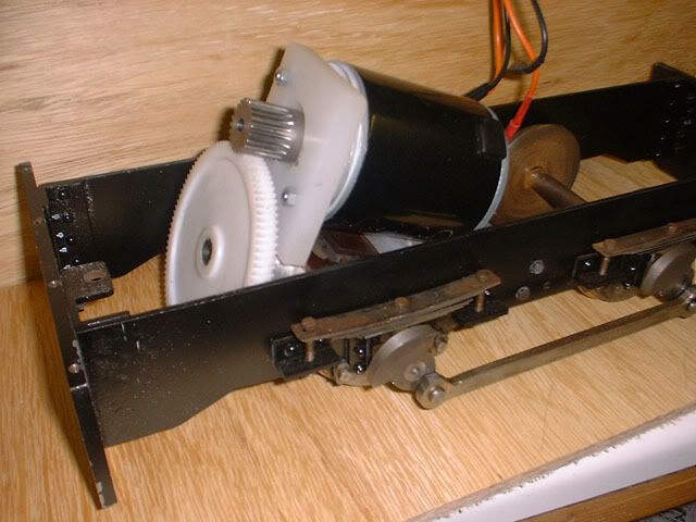
My chassis won't accomodate a motor mounted transversely so my solution was this:-  It isn't obvious but the 'gearbox' under the motor, which is a 120w 12v thing from Parkside, is a block of ally fashioned to mount the smaller bevel gears from two old hand drills, one on the axle and the other on the shaft carrying the large gear. The whole assembly is flexibly mounted so the suspension works. Andy |
|
|
|
Post by meadway on Jul 16, 2010 18:22:04 GMT
Hi Andy.
Thank you for your post and the photograph. You seemed to have solved your drive situation.
I have tried to down load a picture of the chassis to go with my post but it tells me my file is too large.
I hope to put a Y6 body on the chassis so I have a bit more room width wise.
Does your motor have any technical details please?
I am hoping to have a chain drive using the sprockets that are on the axles.
Not being an engineer I am having to learn as I go along. I think I can mount the motor across the chassis, attach a sprocket to the motor shaft and drive the 2 axles. They have 14t sprockets on them.
I have been reading about gear ratios etc and trying to make sense of wheel speeds to motor speed. Initially I have to get a motor that is the correct power, hence my question about your motor.
Regards,
Jeff
|
|
|
|
Post by AndrewP on Jul 16, 2010 23:17:00 GMT
Hi Jeff,
The body is on the loco at present so I'll tell you what I can remember - not a lot!
It's a 3 1/2" gauge loco built for my grand daughter to play on but with that single 120W motor and a 7ah motor cycle battery it runs for hours and can (just) pull my ample frame around our club track on my 4 wheel driving truck.
The gears, motor and controller all came from Parkside Railways, who dchains and sprockets as well, but their website seems to be in transition at the moment.
I'll pull the body Saturday night when it's finished running and get you some measurements.
I'll show my ignorance now - what is a Y6?
Cheers, Andy
|
|
|
|
Post by meadway on Jul 17, 2010 5:53:36 GMT
Hi Andy. Thanks for your reply to my posting. I have found the Parkside Railways site. I didn't realise it is the same as Parkside Electronics. I will seek out some assistance on my predicament. The Y6 locomotives were run on the Wisbech to Outwell light railway during the early part of the 20th Century. Take a look at www.lner.info/locos/Y/y6.shtml . It makes a prototype looking locomotive but without the connecting rods etc. as they are hidden. Cheating I suppose? Regards, Jeff |
|
|
|
Post by havoc on Jul 17, 2010 11:35:46 GMT
To get an idea of the reduction you need follow the next steps (just some numbers added to show): - check the nominal speed in rpm of the motor (spec from an electric scooter motor): 2500 rpm = 2500/60 = 42/second - select the nominal speed you want to drive the loc : 10km/h = 2.8m/s - diameter of your drive wheels: 100mm = 0.1m --> circumference of 0.1 x pi = 0.314m - revolutions/second needed to get that speed 2.8 / 0.314 = 8.9/s - reduction needed = 42 / 8.9 = 4.7 round to 5:1 This reduction will give you 10km/h speed when the motor is running its design speed (max power) with the given drive wheels. When I look at typical electric scooter parts the they use sprockets in the 10-16 tooth range and gears from 54-90 tooth, so this corresponds well. Took my numbers from this site: www.electricscooterparts.com/index.html |
|
|
|
Post by AndrewP on Jul 17, 2010 13:46:26 GMT
Jeff,
Rained off this afternoon so I've had a look, I ended up using a 22 tooth pinion and 90 tooth gear which with 64mm wheels and a motor max speed of 3000rpm gives me a top speed of 5.5mph.
I wrote a simple spreadsheet to work that out since gear sizes were also constrained by what would physically fit. You are welcome to a copy if it would help.
If you can't get a big enough sprocket on the axle then maybe a layshaft to gear it down in two stages? I assume the axles are geared together with the chain and existing sprockets.
Cheers, Andy
|
|
|
|
Post by meadway on Jul 17, 2010 19:00:43 GMT
Hi Andy.
Yes, the 2 sprockets, one on each axle, are geared together by the chain. There is also an idler sprocket which the chain runs on.
I have been able to set up an experiment using a battery powered drill and it seems the existing worm does drive the gear on the axle and consequently the wheels.
The ratio is 4:1 and taking the calculations as the post from Havoc the speed at 3000rpm would be about 9mph.
I have to say I prefer your drive arrangement, however I have to live with what I have got as I can see no way of removing the wheels to fit new sprockets or gears.
I just have to find a motor to replace the Klaxon that has been damaged.
Did you manage to read any details off your motor please?
What is a layshaft please?
Regards,
Jeff
|
|
|
|
Post by AndrewP on Jul 17, 2010 23:09:52 GMT
No details on the motor Jeff, it is the same case size as the 150w 12v ones on the Parkside site so has probably been superceded . By a layshaft I mean an extra, intermediate shaft which would have 2 gears/cogs. One a gear meshing with the motor pinion and the other,a sprocket carrying a chain to the axle sprocket. This gives you 2 pairs of gears/sprockets to get the gearing down done and removes the need to fit a BIG gear on the axle which can be a real problem depending on your wheel size. Thanks, I should have known what a Y6 was, that LNER site is an excellent resource - wasted ages on there today  Cheers, Andy |
|
|
|
Post by meadway on Aug 4, 2010 16:59:59 GMT
My chassis won't accomodate a motor mounted transversely so my solution was this:-  It isn't obvious but the 'gearbox' under the motor, which is a 120w 12v thing from Parkside, is a block of ally fashioned to mount the smaller bevel gears from two old hand drills, one on the axle and the other on the shaft carrying the large gear. The whole assembly is flexibly mounted so the suspension works. Andy Hi Andy. Does your chassis have 4 wheel drive please? Thanks Jeff |
|
steam4ian
Elder Statesman
   One good turn deserves another
Posts: 2,069
|
Post by steam4ian on Aug 4, 2010 21:27:45 GMT
G'day Jeff I think the rods connecting the granks on the axle extensions might be a give away.  ;D Regards Ian |
|
|
|
Post by AndrewP on Aug 4, 2010 22:43:27 GMT
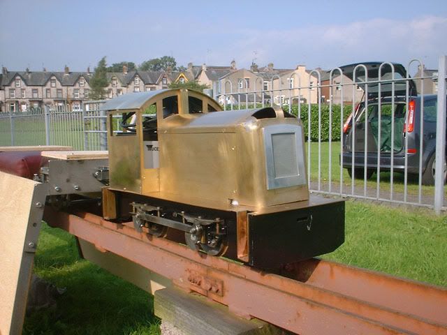
Yes Jeff, via the outside cranks and rods as Ian noted. Fully clothed on it's first test run:-  It has progressed a little but no paint yet - largely because the driver wants it pink   Andy |
|
|
|
Post by meadway on Aug 5, 2010 6:13:18 GMT
Sorry for my stupid question, I wasn't sure whether you had a drive inside the frames. I can see from your photograph that you don't.
The locomotive looks very good. Will it pull a 12 stone driver please?
Regards,
Jeff
|
|
|
|
Post by AndrewP on Aug 5, 2010 9:34:07 GMT
It will pull an 18 stone driver on that 4 wheel truck ! It doesn't much like the clubs bogie passenger trucks though.
Andy
|
|
|
|
Post by havoc on Aug 7, 2010 20:25:55 GMT
Wonderful picture of driver and engine. Keep it that way (so paint it pink if you have to).
|
|
|
|
Post by meadway on Sept 5, 2010 14:34:08 GMT
OK, thanks to all those who responded to this topic.
The present position is as follows:-
I have fitted the chassis with a good quality 12v permanent magnet brushed DC motor. This motor mounted vertically drives one axle via the wheel and gear from an old Stanley hand drill.
This axle then drives the second axle through a chain and sprockets.
I also have a 12 volt lead acid battery. I went this route initially as I want to keep costs down in case the whole project has to be aborted.
Now without going to the expense of a sophisticated motor controller has any member information please on an electrical circuit that will enable me to build a controller?
Regards,
Jeff
|
|
|
|
Post by AndrewP on Sept 5, 2010 20:15:56 GMT
Jeff,
The simplest is probably a resistive controller, I happen to have the 1989 ME detailing a simple electric loco with just such a controller in front of me at the moment.
Drop me a personal message with your email address and I'll feed the mag into the scanner.
Andy
|
|
|
|
Post by meadway on Sept 6, 2010 7:02:20 GMT
Sorry Andy.
I seem to have mislaid your email address.
If you have mine could you drop me a message to contact yo please?
Thanks,
Jeff
|
|
|
|
Post by AndrewP on Sept 6, 2010 10:46:21 GMT
Jeff,
you have a personal message.
Andy
|
|