|
|
Post by spamcanman on Apr 1, 2009 21:58:20 GMT
Hi Ace, here are some pictures. 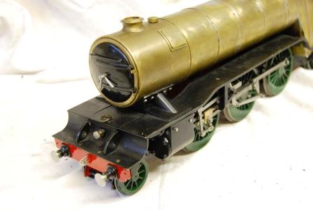 Full working forward/reverser as in the bigger loco's 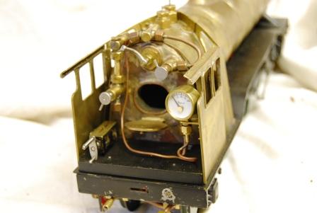 Stainless Steel fire grate as you can see she has not been steamed yet. 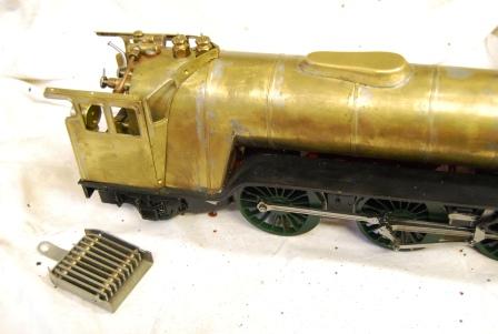 |
|
simonwass
Part of the e-furniture
 Cecil Pagets 2-6-2 of 1908. Engine number 2299. Would make a fascinating model....
Posts: 472
|
Post by simonwass on Apr 1, 2009 22:37:43 GMT
Very nice work, just like the real thing.
|
|
ace
Statesman
Posts: 528
|
Post by ace on Apr 1, 2009 22:40:48 GMT
Thats impressive. Have you managed to source all the casting, wheels and cylinders etc or have you fabricated any parts. Is that a brass outer cover over the boiler.
ace
|
|
|
|
Post by havoc on Apr 2, 2009 10:03:21 GMT
Very nice work you've done on that engine. Really good looking.
|
|
ace
Statesman
Posts: 528
|
Post by ace on Apr 3, 2009 20:22:18 GMT
I have completed my engines displacement lubricator but I'm not sure how this one works as it appears to have only one adjustable regulated feed coming in and a waste pipe exiting from the bottom (how long should this pipe be). Your pic's have shown me where it goes but I can't see how it works, can you explain this one.
ace
|
|
|
|
Post by baggo on Apr 3, 2009 21:33:14 GMT
Hi Ace,
the displacement lubricator does only have the one connection to the steam manifold. Steam enters the lubricator via the pipe and condenses. The resulting water pushes the oil out through the same pipe. Eventually the tank fills completely with water which is drained out through the bottom and then the tank is refilled with oil.
John
|
|
ace
Statesman
Posts: 528
|
Post by ace on Apr 3, 2009 21:47:58 GMT
So the oil is forced out of the cylinder down the pipe (when the valve is opened) to the steam tee at the same time that steam is forcing its way in. Don't mean to sound sarcastic just trying to visualise it.
Does the waste pipe have stopper or tap on the end of the pipe to prevent steam and oil being forced out, again this is not shown on my plans.
|
|
|
|
Post by baggo on Apr 3, 2009 22:55:28 GMT
Does seem a bit hard to swallow but yes, both travel in the same pipe  Martin is a bit brief on the lubricator but I would think the idea is to thread the end of the drain pipe say 1/8" by 40 or 5BA and screw on a little cap to seal it. John |
|
|
|
Post by steamboater on Apr 4, 2009 10:07:42 GMT
Very nice engine. What gauge of copper did you use on the boiler barrel? In the ME articles I believe it says 18 gauge (by two and a quarter diameter) and that would be the coal fired boiler,but I have not been able to find a supplier of that gauge. It is (or seems to be) easier and makes a more robust structure to use 16g. I would aprecciate any feed back?
|
|
|
|
Post by spamcanman on Apr 4, 2009 18:50:54 GMT
So the oil is forced out of the cylinder down the pipe (when the valve is opened) to the steam tee at the same time that steam is forcing its way in. Don't mean to sound sarcastic just trying to visualise it. Does the waste pipe have stopper or tap on the end of the pipe to prevent steam and oil being forced out, again this is not shown on my plans. You don't actually need a drain pipe you can remove the filling screw after steaming and suck up the condense with a syringe. |
|
|
|
Post by spamcanman on Apr 4, 2009 18:56:11 GMT
Very nice engine. What gauge of copper did you use on the boiler barrel? In the ME articles I believe it says 18 gauge (by two and a quarter diameter) and that would be the coal fired boiler,but I have not been able to find a supplier of that gauge. It is (or seems to be) easier and makes a more robust structure to use 16g. I would aprecciate any feed back? Hi, 16g is fine are you sure you cannot find 18g copper plate www.maccmodels.co.uk/home/coppersheet.htm and roll your own. |
|
|
|
Post by steamboater on Apr 5, 2009 3:15:14 GMT
Thanks for the info Spamcanman, May consider the sheet, but the link to supplier is handy in any case.
|
|
ianmac
Part of the e-furniture
Posts: 308
|
Post by ianmac on Apr 6, 2009 23:13:22 GMT
Very nice work indeed!
well done
|
|