Andrew C
Part of the e-furniture

Posts: 447
|
Post by Andrew C on Aug 20, 2011 14:47:04 GMT
I had a bit of a disastrous day in the workshop yesterday. I have made the first of the injector water valves which is now attached to the cab floor by its bracket. As I went to attach the cab floor back onto the drag beam only one or two of the holes lined up. If I lined the holes up the center line down the cab roof point at the outer edge of the chimney. On investigation the whole of the rear extension is not only 5mm lower thar it should be but also offset to the Fireman's side by 2-3mm  To days job: Lift the boiler and see whats what. The boiler came off after a bit of a struggle and removing the ash pan gave me room to work. half the bolts holding the reduced frame to the main frames were not that tight.  I slackened off all the bolts and after a smart smack with a leather hammer the whole rear Assembly was loose and waiving around. It seems to have done up again in the right place this time, after much leaning and pulling on the frame plus constant checking and rechecking. Hopefully it has corrected the problem. |
|
Andrew C
Part of the e-furniture

Posts: 447
|
Post by Andrew C on Aug 21, 2011 17:43:07 GMT
Well the boiler is back on and absolutely everything is fitting better. not only is the cab level it's pointing in the right direction also the grate and ash pan are a closer fie and the original plate on the top edge of drag beam now fits under the cab.  JJ I owe you an apology you were right the frame would move far enough. |
|
|
|
Post by Deleted on Aug 21, 2011 18:25:34 GMT
Hi Andrew
Glad to hear that you've got it all lined up - it's worth making the effort to get it right!
Hopefully the pony truck wheels will still touch the rails with the rear frames moved higher - mine do, although they don't carry any load to speak of - which is no bad thing, since it's more weight on the driving wheels and hence more traction.
Regards, John
|
|
|
|
Post by Jim on Aug 22, 2011 11:22:06 GMT
Hi Andrew,
Just dropped by to see what was happening on the Britannia front and saw your latest post. Are you assembling a Winson/Modelworks Britannia?
Good to hear that all has gone as planned and now back together again.
Best wishes,
Jim
|
|
Andrew C
Part of the e-furniture

Posts: 447
|
Post by Andrew C on Aug 23, 2011 20:34:43 GMT
Hi Jim Yes some would say I'm cheating.  There were/ are quite a few bits missing safety valves and regulator. half the clacks, the water valves for the injectors to name but a few. What with these and all the plate work to make fit it should take me some time to fix. I think it's how you finish it off that counts the most. When I start on the Caprotti Black5 that will be a challenge! I have Don Young's drawing and the front Boigie started but not much else. |
|
|
|
Post by Jim on Aug 23, 2011 23:01:26 GMT
That's not cheating at all Andrew, it's all model engineering.  Couldn't agree more on the importance of how you finish off a model. The final finish including painting can make or break a model. A Caprotti valve geared Black 5? I'm already trembling at the thought of all that work  Best get back to Boadicea to steady my nerves. Keep up the good work. Jim |
|
|
|
Post by Deleted on Aug 25, 2011 9:03:18 GMT
Hi Andrew
You asked in Jim's Boadicea thread about stiffness of the reverser gear and whether your PTFE valve rings might be too tight.
My reverser gear was very stiff to start with (I even broke one of the plastic universal joints, which are quite tough) but I discovered that the boiler was pressing down heavily on the weighshaft. I cut away the cladding and insulation around the weighshaft and that seemed to cure the problem - the reverser turns very easily now. The PTFE rings should be an easy push fit in the valve cylinders when cold. They will expand when hot. I was told it's best to make the rings with a few thou clearance between the inside of the ring and the bobbin, so that when the rings expand and can't move any further outwards they can deform inwards. The elasticity in the PTFE should then prevent the rings being forced too hard against the valve cylinder.
Regards, John
|
|
|
|
Post by Jim on Aug 25, 2011 13:35:23 GMT
As a follow on to John's comment I have an article on making the PTFE valve bobbins as described by John, if you think it would be of use I can email it to you. I will be making my valves along the lines John mentions.
Jim
|
|
|
|
Post by Jim on Aug 27, 2011 11:46:00 GMT
Hi Andrew,
Sent article and photos re PTFE valves to your personal email address.
Jim
|
|
Andrew C
Part of the e-furniture

Posts: 447
|
Post by Andrew C on Aug 28, 2011 7:15:35 GMT
Hi Jim yes I had seem them thank you. But have only just got round to replying. JJ I had wondered if those joints were strong enough. They are for the model boat fraternity. I only got one with the engine so had to find another, which I managed to get from Camden models in London. A month or so back My next door neighbor came by to admire my latest engine took one look at the universal joints and said did I want to trade them for some steel ones he had? Turns out he had bought them for a boat but decided the corrosion would be to bad so was on the lookout for plastic ones  So a trade was made and the steel ones went on the engine yesterday. I have had to replace the drive rod because I had cut it to length for the bigger plastic joins.  The only rod I had to hand was slightly bigger diameter but it still misses the boiler cladding so that should be fine. I have spent some time getting the cladding and cork insulation to fit snugly which seems to be paying dividends at the moment. |
|
Andrew C
Part of the e-furniture

Posts: 447
|
Post by Andrew C on Sept 24, 2011 6:05:11 GMT
To continue Jim's comment about the finish of the model is important here is a Model works Brit just sold by Station road steam It is amasing how you can look past the incorrect hand rails and the round head screws in the cab side. If my paint job is half as good as that I'll be happy.  There are more on Station Roads site under stock code 5156 Attachments:
|
|
Andrew C
Part of the e-furniture

Posts: 447
|
Post by Andrew C on Oct 2, 2011 6:51:52 GMT
I decided to cut the hand rail so I dont have to pull the whole thing out if I need to either remove the smokebox or get the pipe off the top feeds. When it's closed it is a tight fit and you can't see the join. Attachments:
|
|
Andrew C
Part of the e-furniture

Posts: 447
|
Post by Andrew C on Oct 2, 2011 6:54:47 GMT
here closed. The circles are for the rough position of the mud hole door and washout plug. Attachments:
|
|
|
|
Post by Jim on Oct 2, 2011 10:45:26 GMT
That's a very neat idea Andrew  I've stored it away for use on Boadicea.  Unfortunately house painting and repairs have pushed model engineering to one side for the present but the jobs are nearly done so fingers crossed... |
|
Andrew C
Part of the e-furniture

Posts: 447
|
Post by Andrew C on Oct 2, 2011 21:02:15 GMT
Hi Jim If you use this remember tha main handrail need only just go into the knob by the top feed. As the short bit only has the two knobs, the one on the smoke box and the first on the cladding I made sure the dont quite line up so as to nip the rod  Andrew |
|
Andrew C
Part of the e-furniture

Posts: 447
|
Post by Andrew C on Oct 9, 2011 19:41:40 GMT
Well have had a one of those two step back days today. Took the engine over to the track we are building at my dads. Put Robert Burns on the deck and the whole of the back end is still twisted the pony wheels touch on one side and not the other.  it is so bad that the flange is above rail height! Think I am going to have to lift the boiler and try and reset things again. I also need to put the pony back together square. It would seem who ever had the engine before left alot of stuff loose. There is no vertical movement in the back end at all Andrew |
|
Andrew C
Part of the e-furniture

Posts: 447
|
Post by Andrew C on Oct 10, 2011 21:32:44 GMT
Have ordered the mud hole doors for the boiler today plus the steam heating pipes in an attempt to chear me up a bit  . I have the wash out plugs to fit. I just think it will look too bare along the top of the firebox and between the chimney and top feeds without. |
|
Andrew C
Part of the e-furniture

Posts: 447
|
Post by Andrew C on Oct 22, 2011 8:33:34 GMT
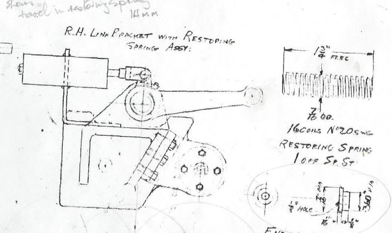
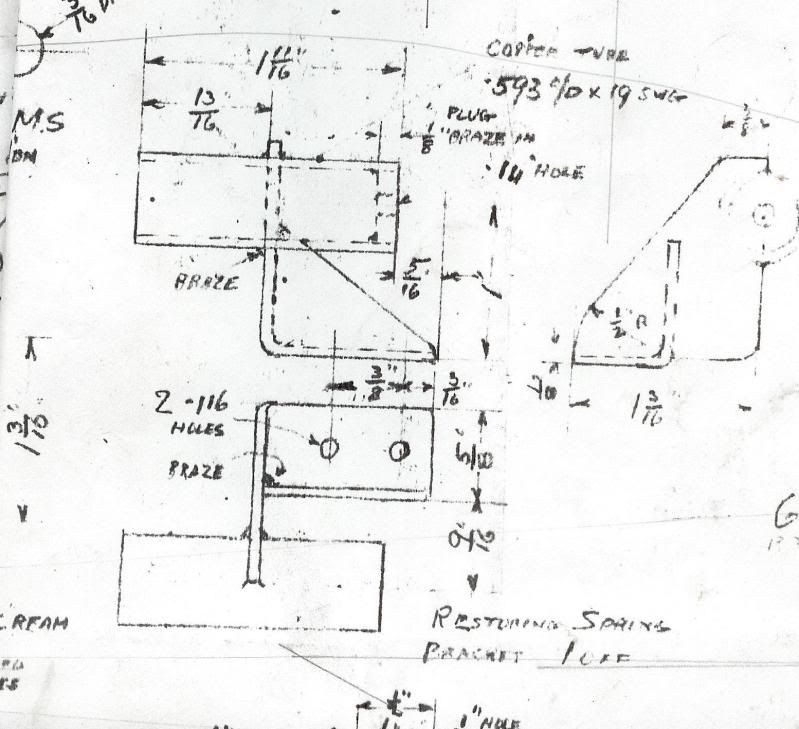
I spent part of last weekend in the workshop sorting pipework on the backhead. As I was fitting the pipe for the whistle realised there is somthing missing by the weigh shaft. Looking at some photos there is a cylindrical device on the righthand side attached to the reversing weigh shaft. I asume it is some sort of damping device? Does any one have the detail dimension and how it is fitted?
|
|
|
|
Post by Jim on Oct 22, 2011 11:09:41 GMT
I think what you're refering to Andrew is the restoring spring. I was going to PM you with the details but have posted them here instead. There's not a lot of weight in the valve gear so I used a lighter spring than specified with the option of changing it later if needs be  Hope this helps. Jim   |
|
|
|
Post by Deleted on Oct 23, 2011 8:43:32 GMT
Hi Andrew Modelworks just provided a dummy version - a solid brass cylinder 43mm long by 16mm diameter. I think that they intended it to be fixed to the underside of the running board, but I made a bracket to fix it to the weighshaft casting. There's a photo of my setup here: www.britanniabuilder.com/kit13.htm#9408It's interesting that Jim's drawings show a working version, although my reversing gear does move up and down quite easily without help from a spring. Kind regards John |
|