|
|
Post by Jim on Jul 10, 2011 23:04:10 GMT
There is good news and bad news.  The good news is that over the last week or so I've been in contact with Don Ashton who has kindly offered his expertise and valued advice on the ways to get the best out of Boadicea's Walschaert's valve gear. In the process I've started to get a better understanding how the valve gear works while Don claims the spin off for him is that it gives him another design to examine. The bad news is that for reasons unknown Perrier designed the return crank with a 1/8" gap between it and the connecting rod with a compensating 'joggled' eccentric rod to realign it with the expansion link. At the time I didn't give it much thought but I now realize that the 'joggle' will need to be quite severe and that the 1/8" gap is not required. So it's back to the drawing board to see how things can be sorted, sadly there is a real possibility of a remake of the cranks and crank pins  Jim |
|
|
|
Post by Deleted on Jul 11, 2011 9:56:09 GMT
Hi Jim Do the Perrier plans show a bend in the eccentric rod? This photo shows the eccentric rod on my Modelworks Britannia (still in need of cleaning after yesterday's run!), where the misalignment is taken up by having the fork at the front end offset behind the line of the rod. I think it looks pretty acceptable when viewed from the front. The shape of the rear end is pretty much as the prototype. I think that at least part of the problem is caused by the return crank being a lot thicker than scale. Hope this helps. 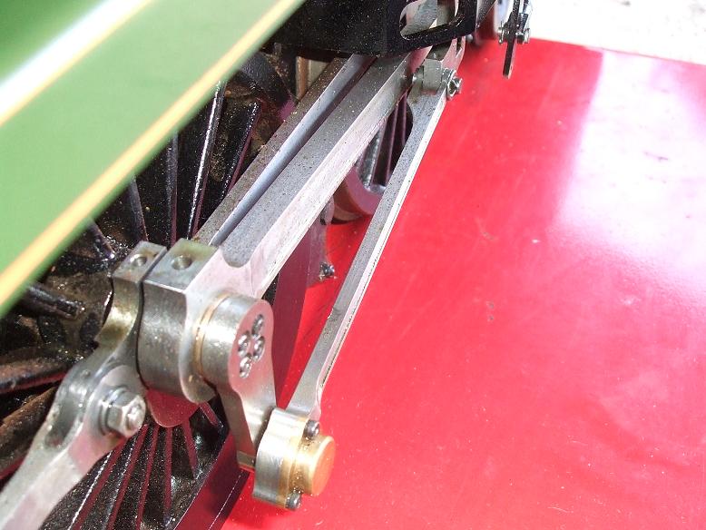 Kind regards John |
|
|
|
Post by donashton on Jul 11, 2011 10:14:44 GMT
When the return crank pin is farthest from the cylinder, that's when the clearance is the tightest, and many LMS return cranks were radiused off just beyond the four bolts to give clearance to the eccentric rod. Many eccentric rods had a shallow crank in plan in addition to the offset front end mentioned by John.
Don
|
|
|
|
Post by Jim on Jul 11, 2011 14:06:53 GMT
Thanks Don and John,
John, that is the clearance my return crank should have but currently as per Perrier, it is almost 1/4" further out due to the combination of an extension to the connecting rod's big end bush and a shoulder to the back of the return crank that yours and the prototype lacked. You can see it in the photos I posted here earlier in this thread.
Don, you're spot on with the comment on the clearance when the return crank is at BDC. The Britannia works drawings clearly show the radius you mention and of course the radius rod is straight.
Many thanks to you both for the information.
Jim
|
|
|
|
Post by Jim on Jul 12, 2011 3:53:45 GMT
I've included the attached photo to show just how much clearance there is between the return crank and the connecting rod if building to Perrier's plans as compared to that in JJ's photo of the crank on his Model Works' Britannia. My next job will be to don a white coat, administer some anesthetic in the form of a soothing ale and extract the two crank pins. All going well I'll machine the pins to size, reduce the extra length on the big end bushes then collapse into a chair with a restorative ale.  Jim 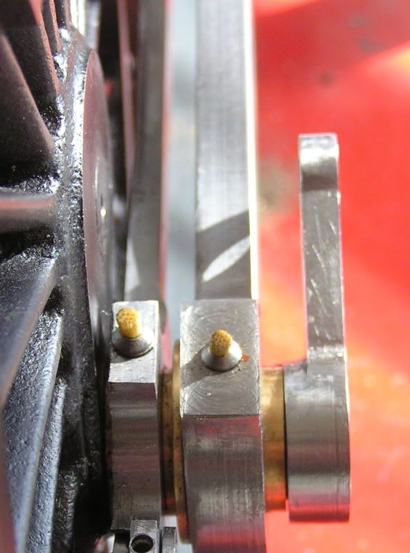 |
|
|
|
Post by Jim on Jul 20, 2011 10:33:46 GMT
With a soothing ale to calm the nerves the warrior queen was rolled over onto her back, her drivers were removed and under light sedation and much to my relief the return crank pins extracted more or less painlessly.  I decided to set the whole assembly in the 4 jaw chuck to turn down the pad on the crank to size as the reduced pad would now be just within the connecting rod big end bearing. In the photo the tail stock chuck was used to hold the bearing while the jaws were lightly tightened. With the tail stock chuck withdrawn the jaws were then tightened to run true on the DTI. 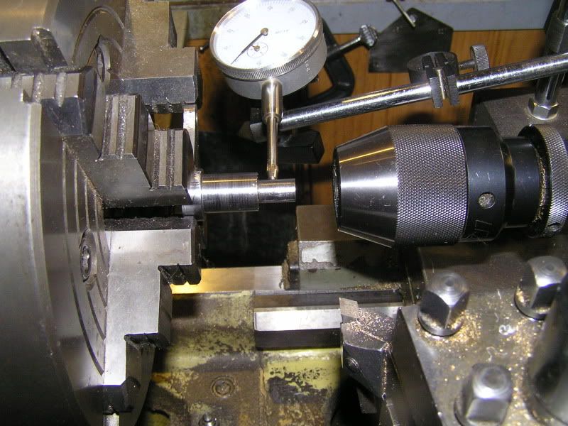 Taking very light cuts the the first crank was completed. The 'before and after' photo shows the result 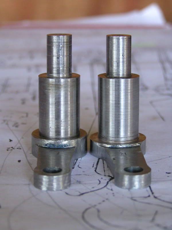 With both cranks completed the excess was turned of the big end bearings and the crank pins similarly shortened. 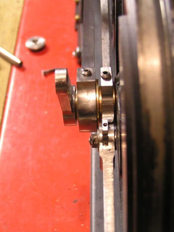 The new layout means the return crank is in line with the expansion link so there will be no need for the joggled eccentric rod shown in the Perrier plans. With Boadicea right way up and her dignity restored all that remains is to reset the throw of the return cranks, oh and find all my oiler corks that went missing.  Jim |
|
|
|
Post by keith1500 on Jul 21, 2011 16:57:26 GMT
Good to see you are making positive progress with the loco Jim,
I like the idea of using two nuts for measuring the ports and the use of Delrin for a test valve.
I am now drawing the layout of my Valve gear using CAD and its amazing how much more you start to appreciate its geometry and the relationship of each of the components.
Keith
PS What are you using as "corks" on your rods?
|
|
|
|
Post by Jim on Jul 22, 2011 1:00:32 GMT
Hi Keith, The two nuts on the threaded rod proved so useful that I have now made a permanent one with a lock screw slide in place of the top nut. I must say Don Ashton has been a great help and like you I've found drawing the valve ports as they really are from actual measurements a great help in seeing what's actually happening and how varying the bobbins changes things. I tethered the dimension from the datum at the front of the valve cylinder to the front of the valve to give me an instant 'distance in' readout which I could check against the actual valve or vice-versa. It's a lot of fun and as you say it gives you a real appreciation of the chain of events along with valuable information. I must say I'm surprised at how effective the test valve bobbins are and how easy they are to make, I've made three so far as I varied the lap on the left hand valve. As Don says, 'If you have to make 4 individual bobbin ends, so be it'. I won't have to do that but the right hand bobbin will be slightly different to the left hand. Edit: Sorry Keith forgot to say the 'oiler corks' are made from a couple of bamboo skewers I 'liberated' from the domestic supplies.  Jim |
|
Smifffy
Statesman
  Rock'n'Roll!
Posts: 943
|
Post by Smifffy on Jul 31, 2011 17:49:35 GMT
Hi Jim,
I have just been going back over this thread - as per my reply in here, I'm just a few weeks behind you.
You have done a lot of work here around your valves - checking the dimensions and making test bobbins. Can I ask why you have had to do all this (bear in mind, that despite my choice of Locomotive, I am a novice here!) ? Is it a case of ensuring that you get the best possible out of your valves - or are you drawings lacking in detail ?
For my Royal Scot, Martin has given all the various dimensions (valve ports, bobbins, etc.) with the exception of the Eccentric Rod which he states "Approximate, check from job".
Where I'm going with my question (I guess) is to try and understand whether what Martin has specified will do, or will I need to follow in your footsteps and make more 'customised' valve gear......of course, I'm hoping for the former!
Cheers
Smifffy
|
|
|
|
Post by Jim on Jul 31, 2011 21:58:04 GMT
I'm sending you a more detailed PM on this Smiffy.
Like you this is my first venture with a loco with Walschaert's valve gear. I'd read a bit about the problems that can arise and that coupled with some concerns unfounded it would seem, with the valve gear details in the plans led me to do some fairly careful checking.
Jim
|
|
|
|
Post by Jim on Aug 7, 2011 8:24:21 GMT
At last the job of milling all the links and rods for Boadicea's valve gear is coming to and end with a start being made on the eccentric rods. The exact distance between centres for each side was taken from the adjustable test rod and transfered to the respective eccentric blanks and as the photo shows a counter bore was added to the crank's big ends to house the bearing retaining plates. Buttons to indicate where the radiused ends would start along with the positions of the three retaining screws that will hold the final brass cover plate over the big end bearing were also added. The photo shows the rod on the milling fixture with the indicator buttons in place 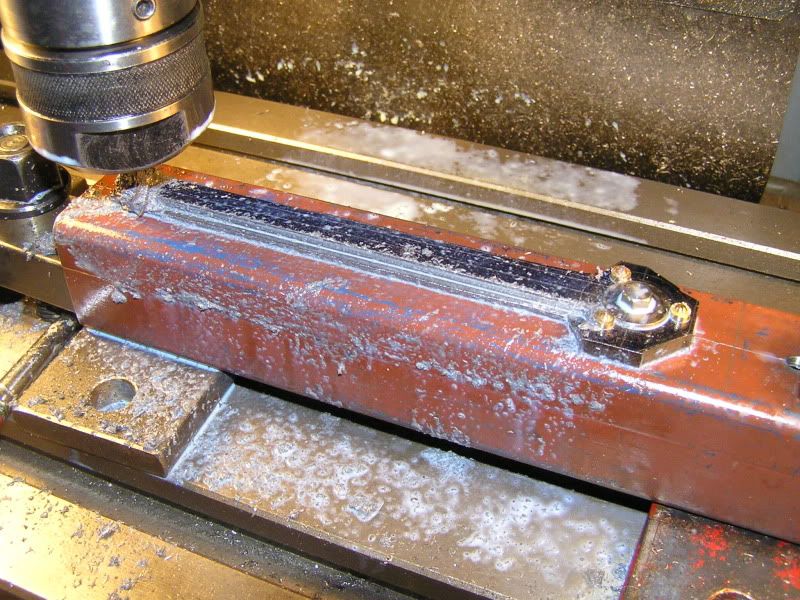 This photo shows the bearing mounted on the crank pin with retaining plate temporarily fitted behind it so I could check clearances. 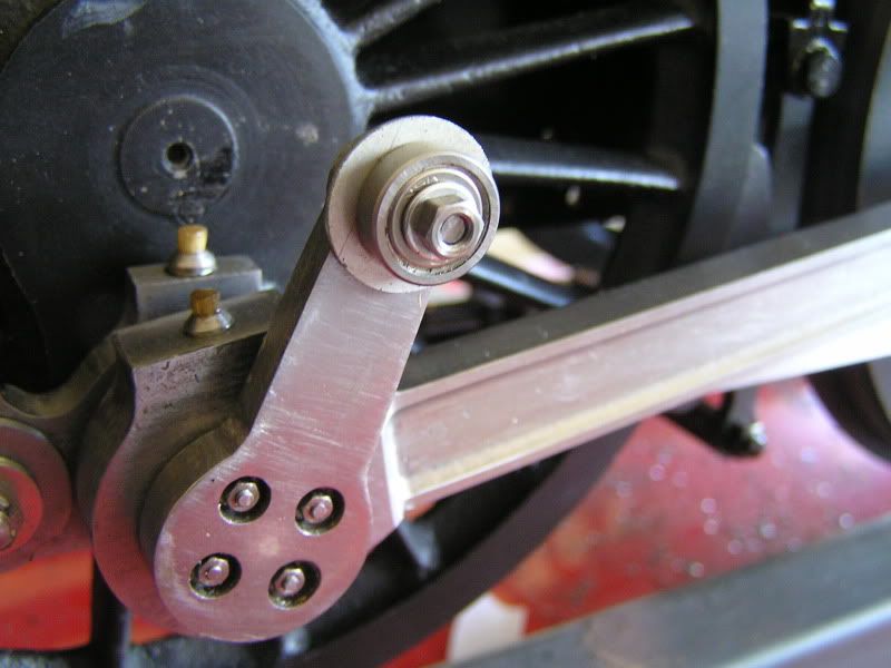 Fingers crossed this will be the last of the milling and fluting of rods for Boadicea.  Jim. |
|
|
|
Post by drjohn on Aug 7, 2011 11:50:23 GMT
Hi Jim
Apologies in advance for my ignorance, but I am confused.
The positioning of the return crank in Walshaerts valve gear is the most critical setting (Don Ashton correct me!) so two points:-
It looks like your main cranks are a turned finish (albeit with the wonderful tangential tool), but will this not generate unnecessary wear on the main bearings? and secondly, having removed the crank pins from the wheels, with the return crank fixed in position, how did you get them back in the perfect place? How are they fixed? Pressed, or loctite?
30 years ago, I did a Brit to Norman Spinks' plans and he used the standared split, pinch and pin type of attachment for the return crank - albeit you could add the scale billy-do on the outside later.
DJ (being a bit dense today!)
|
|
|
|
Post by Jim on Aug 7, 2011 12:59:30 GMT
G'day John, You're right John, the Perrier Plans use a split pinch and pin crank with an added little square plate to make it look like the original before the change to the LMS 4 stud style. The return cranks are fixed to the crank pins as in the real thing with a locking 'tongue and groove' and held in place by the 4 studs. Don Ashton has a copy of the works drawing on his site which I used as the pattern. I glued the crank pins in with Locktite in 609 and I can swear to its holding powers as I found out the hard way when I had to get the pins out again after I found that, as drawn, they were out of alignment with the expansion link. Perrier had his reasons but somewhere along the line things changed so the gap was no longer needed. To get them back on the right pitch circle I used a modification of Don Ashton's idea and used the centre pip in the end of the axle to locate a card disc drawn to the crank's pitch circle. The tangential cutter is a doddle to use and sharpen not to mention the cutters tendency to 'knock down' if I get a bit carried away on the lathe.  Jim |
|
|
|
Post by donashton on Aug 7, 2011 14:59:50 GMT
Hi DJ,
I'm in no position to correct someone who is right in the first place. The length of the return crank is not absolutely critical but the setting most certainly is, as you say. The reason is that the setting affects the timing. Any slight length discrepancy is automatically accommodated in the 'check from job' eccentric rod length to preserve the primary lead timing.
Where the return crank is a clamp type, the clamping action supposedly expected to resist the driving forces, how is accurate radial positioning any different from Jim's work? Like Stephenson's gear eccentrics there is only one correct place and it is therefore quite illogical to have them adjustable.
The method used by Jim applies equally well to the square drive return cranks, though my preference is to fit the return crank/pin assembly by jig from the wheel bore BEFORE pressing onto the axle. Then undo the return crank and store until required.
Don
|
|
|
|
Post by drjohn on Aug 8, 2011 0:00:09 GMT
Hi Don & Jim
OK, but I got the impression from your photos that the return crank was inexorably fixed to the crank pin, hence I wondered how you managed to loctite it into the wheel with the coupling rod and con rod in place - you now have explained - thanks.
I haven't seen your jig idea Don, will look later when my internet connection is usable. What I do for jigging the return cranks is, when I'm drilling the pip in the driving axle, I drill a little deeper and thread the hole, then you can screw the jig into the axle and be certain it's in the right place - if you see what I mean.
DJ
|
|
|
|
Post by donashton on Aug 8, 2011 9:26:52 GMT
Hi DJ,
We both have the same principle, which the 'words and music' never includes.
Many full size drawings state the angle to four figure decimals, which proves the draughtsman's ability to handle trigonometry and the cosine rule, but does not say how the Works actually achieved accuracy. Does anyone out there know?
Don
|
|
|
|
Post by Shawki Shlemon on Aug 10, 2011 10:20:41 GMT
YES , by eye sight , if it looks OK then it must be wright . ;D
|
|
|
|
Post by Jim on Aug 12, 2011 10:31:22 GMT
Back on task with Boadicea having spent the last couple of days milling out the bearing housings on the crank ends of the eccentric rods. The rotary table now looks like a convict relic with lots of broad arrows penciled on it to remind me which way to turn the wheel that rotates the table, it wouldn't be the first time I turned it the wrong way just a the worst possible moment  There's still a lot of milling and fluting to go not to mention brazing up the fork ends of the rods but at least the end is now in sight. The photos show the profiled crank end with the three holes tapped 10BA for the securing studs. 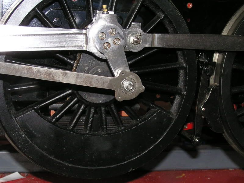 The brass cover which was turned from brass bar, spigot for turning still attached. 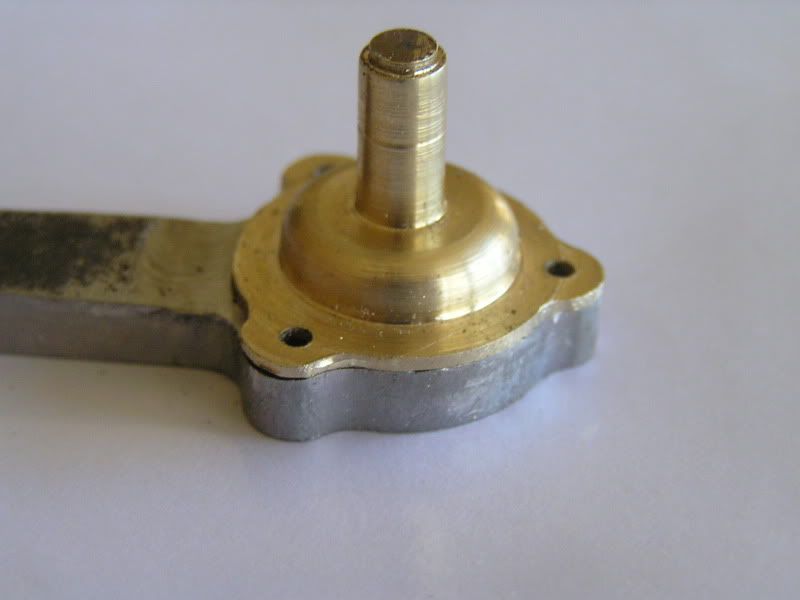 and finally the first cover fitted and held with temporary slot head screws. 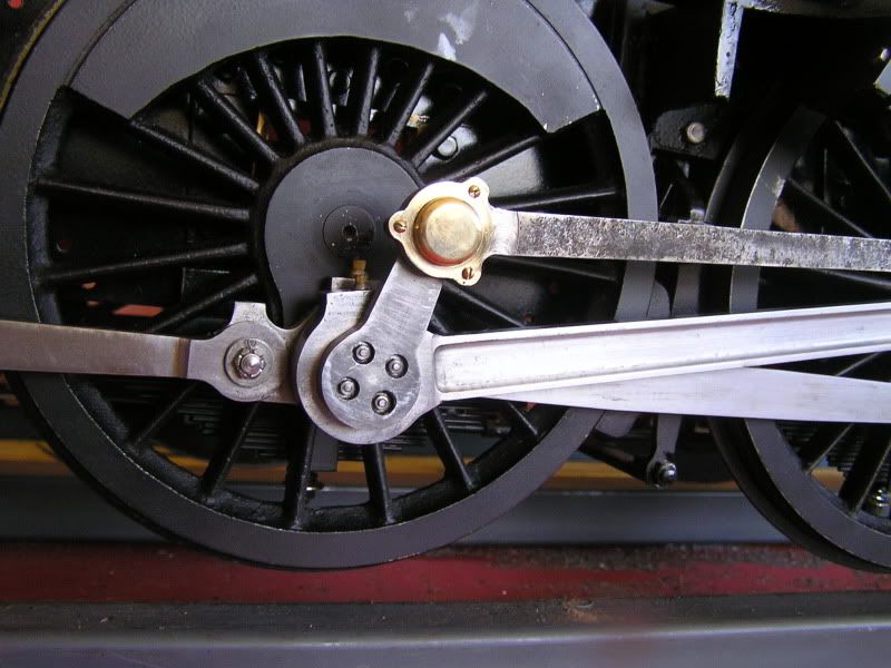 The filling and drain plugs that featured on the real things will come later. Jim |
|
|
|
Post by Jim on Aug 14, 2011 6:51:30 GMT
At last the left hand side eccentric rod is finished and with it completed there is only the right hand side to go. I don't know about others but I find doing these jobs pretty tense, as constantly in my mind is the knowledge that a loss of concentration and hours of work are ruined. I've been there before  When both sides are finished I'll fit the plugs to the brass cover plates. 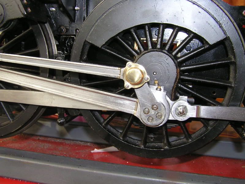 Jim |
|
|
|
Post by Deleted on Aug 14, 2011 8:52:58 GMT
Looking great Jim, top stuff as usual...  Pete |
|