|
|
Post by Jim on Nov 8, 2014 5:39:46 GMT
Today's job has been to trim the excess from the stay tails then using a flap wheel polish the rough ends down to but not into, the silver solder. I don't want to open a weep or worse  It's a tedious task and the day's effort has the crown, the fireman's side of the fire box and the throat plate done. I should complete the rest tomorrow then get serious about the cleading. After all that I feel a soothing ale might be the way forward now. Ah Bliss  Jim 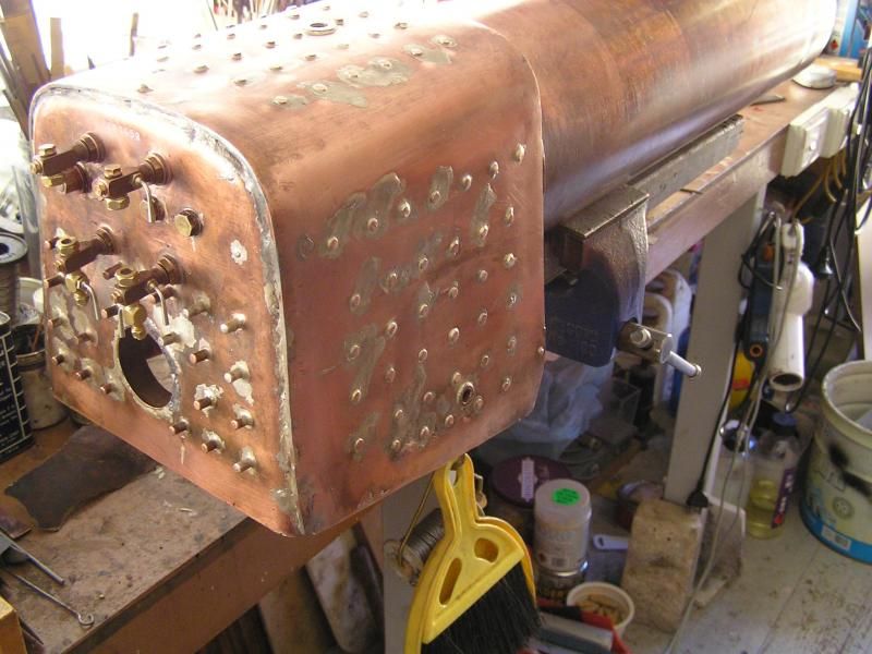 |
|
|
|
Post by runner42 on Nov 8, 2014 6:35:18 GMT
Congratulations Jim on passing the boiler test. Does the boiler inspector mark the boiler in any way to provide visibility that for future it was the boiler that was inspected, or is it done on a paperwork basis only?
Brian
|
|
|
|
Post by Jim on Nov 8, 2014 8:08:43 GMT
Thanks for the comment Brian. In answer to your question, all the boiler's details are entered into the club's official boiler register and signed off by the inspector and witness and at that point a registration number is issued which I stamped in. That way any mistakes or mishits are my fault.  The registration mark consists of 2 letters 'N' for New South Wales and in my case, 'P' which identifies the registering club as Orange Model Engineers, followed by the actual numbers identifying the boiler. You can just see the registration number above the top two water gauges. The Boiler Certificate is issued following the steam test. Jim. |
|
uuu
Elder Statesman
   your message here...
Posts: 2,864
|
Post by uuu on Nov 8, 2014 8:23:00 GMT
Interesting to see the number stamped at the top. Much easier to read when the boiler is in the loco, than having it down on the skirt.
Wilf
|
|
stan
Seasoned Member

Posts: 110 
|
Post by stan on Nov 8, 2014 22:27:07 GMT
Hi Jim
I don't know if its any help to you but Les Warnett tells you to glue strips of wood round the fire box to form a frame to support the cleading, I have used Balsa wood for my 9F, I don't know what other members think, this keeps it clear of the stay ends.
Stan
|
|
|
|
Post by Jim on Nov 8, 2014 22:52:51 GMT
Hi Stan, Thanks for that suggestion. I must admit I hadn't thought of using wood strips and that's a bit of a worry for me memory wise as it is exactly what I did with my Burrell.  I'm keeping the long stay tails on the fire hole door plate too for the time being in case they are needed as anchor points. You've probably seen it but John Johnson's Britannia Build site found here: www.britanniabuilder.com/ Kits 18 and 18B. is a great source of ideas and information for anyone building a Britannia or a Clan for that matter. Thanks again Stan for the reminder. Jim |
|
|
|
Post by ejparrott on Nov 9, 2014 9:16:31 GMT
You could always put the proper BR crinoline support frame on...
|
|
|
|
Post by Jim on Nov 9, 2014 10:47:31 GMT
Thanks for the suggestion Ed. Why is it that every time I think I have a you beaut wheeze of a short cut that no one will know about I get found out.  Jim |
|
|
|
Post by Geoff (Carlisle) on Nov 9, 2014 21:47:34 GMT
Hi Jim, when i insulated the V3 (Enterprise) loco i used 1/8" thick cork sheet and stuck on with Araldite resin and it has never moved, it's just a nice thickness below the boiler cladding.
Geoff (Carlisle).
|
|
|
|
Post by Jim on Nov 10, 2014 5:56:43 GMT
Today has been spent drawing out what will become the former for the cleading at the front of the fire box. The photo shows the progress to date with the cleading following the line of the fire box as it comes down the side. The Perrier drawings show this as a vertical section but I suspect it was drawn that way to hide the hex heads of cross stays over the top of the fire box. 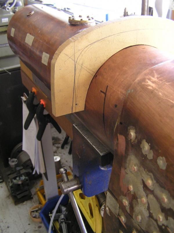 The flowing lines of the cleading in the photo kindly sent to me by Stan Pearson shows how the cleading should go. 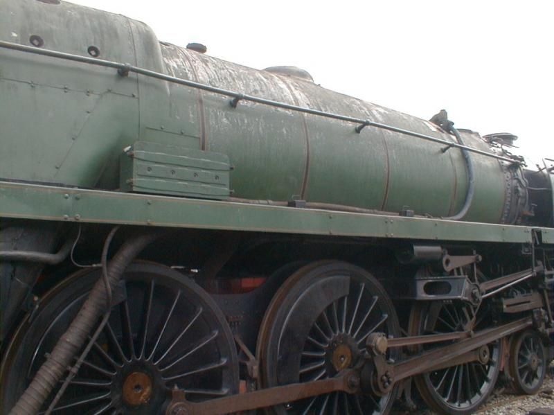 Jim |
|
|
|
Post by Jim on Nov 11, 2014 5:51:57 GMT
There's still a bit of adjusting to do but the former for where the fire box cleading joins that over the boiler barrel is beginning to become clearer. I also need to join the two halves of ring which represents the approximate diameter of the boiler barrel cleading. With the two halves in place I should be able to see how it will all sit above the frames when the boiler is in place. The string line shows the top profile of the cleading. Things are slowly starting to take shape. Jim 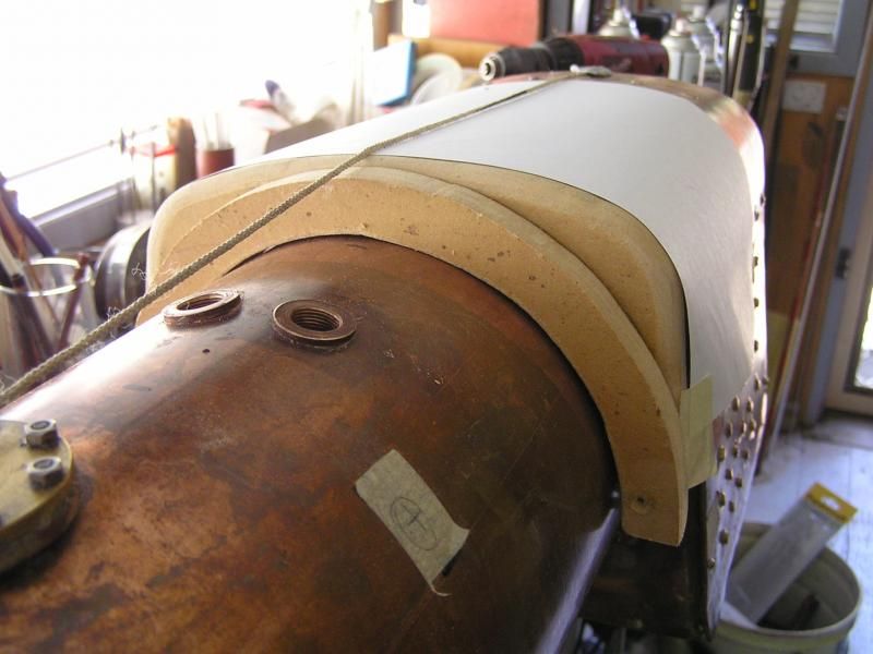 |
|
|
|
Post by Deleted on Nov 11, 2014 8:50:24 GMT
looks great Jim....not an easy part to do....your approach looks very sound and will give you the shape you seek....top stuff sir...  Pete |
|
|
|
Post by Jim on Nov 11, 2014 10:02:41 GMT
Thanks for your encouraging comment Pete. One of the things I've already found is that I will have to reduce the height of the transition piece. Although made as per the JP's drawings it. a) creates too great a slope back over the fire box toward the cab and, b) generates a diameter for the cleading that won't fit between the frames.  I'm fairly sure this can be sorted by re jigging the transition piece and in doing so the angle of slope back over the crown of the fire box will be much closer if not the same as that on the works drawings. This will also result in reducing the 'big end' diameter of the cleading over the boiler barrel with a close but workable fit between the frames. The slightly reduced cone in the cleading will also mean the safety valves will have the correct level of visibility. In all this I find it very useful to be able to compare things from the same angle as that in a photo of the prototype. It does create a few "Oh no!" moments but worth the effort. Jim |
|
|
|
Post by Jim on Nov 12, 2014 5:54:59 GMT
Well today's effort saw a return to the 'drawing board' (2D CAD) and a new drawing of the fire box front including modification to fix the problems encountered yesterday. The height of the former was reduced to 16.5mm and the bottom half of the the crinoline reduced to 12mm. The slightly elliptical bottom half of the crinoline blends nicely with the semi circular top half and it will be be difficult to actually see beneath the foot plates. 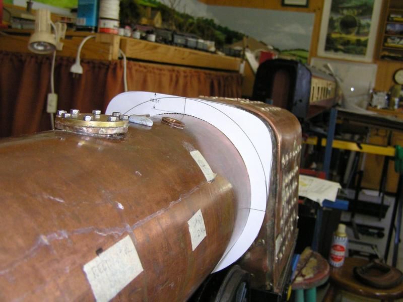 With the pattern now established it was transferred to to the MDF, cut out and had the top curves formed with a router. The MDF former will be used to create the actual metal shaped front. 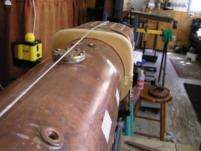 A paper version of the cleading was added along with the safety valves. The string line shows the top line of the cleading going forward to the smoke box and sloping back over the fore box. The string line will also give me a reference for determining the diameters of the remaining crinolines. 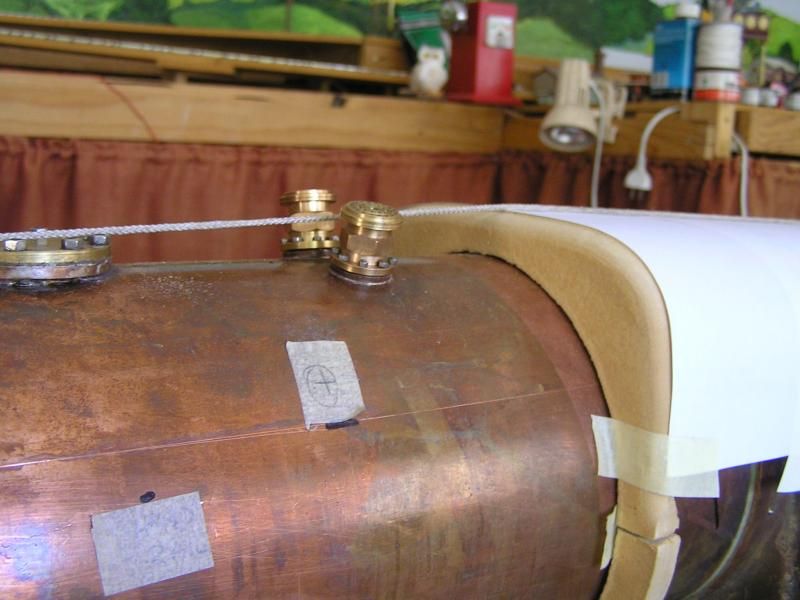 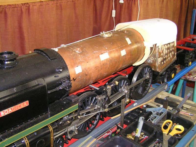 After the boiler work it's nice to get back to Boadicea and see her start to take shape. Jim |
|
|
|
Post by Roger on Nov 12, 2014 7:20:14 GMT
That looks so good Jim, you really must feel that the end is finally in sight.
|
|
|
|
Post by Jim on Nov 12, 2014 7:32:21 GMT
Thanks Roger the end is a bit closer than it was a few weeks back as I chased boiler weeps and worried if the boiler would pass the pressure test. Once the cleading is fitted things will really start to move ahead. At present though I just want to make sure I have the crinolines right as they will determine the final outline then it will be back to photos to determine just how the cleading was cut, shaped and fitted. Time for a soothing ale now while I think about it all   Jim |
|
Andrew C
Part of the e-furniture

Posts: 447
|
Post by Andrew C on Nov 12, 2014 8:17:50 GMT
Looking good Jim. Are you intending to clad the firebox in one pice made to look like lots of bits ?
Also how had you thought of mounting the centre pivot of the regulator ? When operated there is quite a bit of force put through it and you don't want it flexing. Mine has two studs silver soldered to the barrel.
Andrew
|
|
|
|
Post by Jim on Nov 12, 2014 9:42:51 GMT
Hi Andrew, good to hear from you.
At this stage I intend silver soldering the pivot bracket to the boiler barrel once I've established its correct location. As you say it carries a fair load as the regulator rod is pushed and pulled. The other thought I've had is to attach the pivot to a band round the boiler with the band's constricting screws concealed beneath the cleading. That may in fact be the easier way to go. I need to give that a lot more thought.
As for the fire box I think at this stage I'll try and make the curved sections between the sides and front of the fire box as per the prototype. For the rest I'll do it as flat sheets marked to look like sections. A few card patterns will need to be made first though.
Jim
|
|
|
|
Post by ejparrott on Nov 12, 2014 9:55:04 GMT
To me it's the one let down of the Brits, that awful long regulator rod. I used to drive the first Winsons Brit to run quite regularly, that was always it's let down. The 9F and Standard 4 I'm familiar with are much better having shorter rods to a dome mounted regulator.
|
|
|
|
Post by Roger on Nov 12, 2014 9:57:38 GMT
Maybe it's possible to design a more balanced regulator that keeps the operating forces to a minimum?
|
|