|
|
Post by fostergp6nhp on Feb 6, 2014 21:15:23 GMT
|
|
|
|
Post by Rex Hanman on Feb 7, 2014 12:00:00 GMT
Nice job on that beam. My shoulder is still useless and keeping me out of the workshop.  It's given me plenty of time to think about things and though I know I've got the ends of the beam slightly wrong I'm inclined to leave them as they are. The forces involved in the full size were probably considerable but scaled down I can't see the two pieces of 5mm steel bending, especially as they are stiffened by the bottom fulcrum bracket. Therefore I might leave out the stay bar. If there's a problem I can always add it later. It's totally invisible anyway, hidden behind the cylinders and front drivers. I'm really impressed by your radius arm...nice work forming the "T" section and getting the bends right. Any tips on how you did it? I fear distortion when brazing or silver soldering the vertical bit on.  |
|
|
|
Post by Laurie_B on Feb 7, 2014 15:27:32 GMT
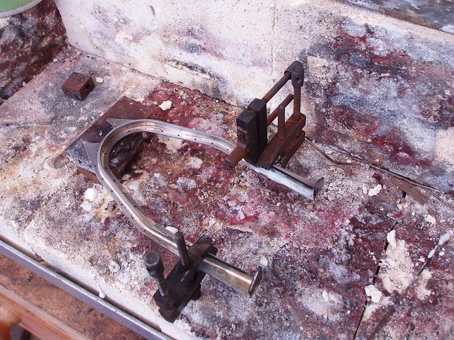
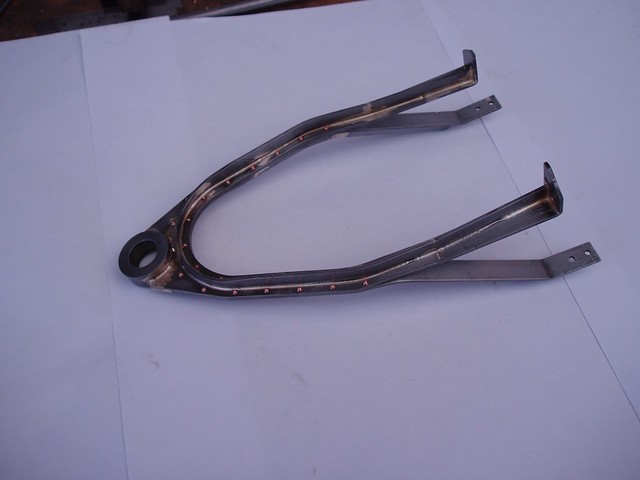
Nice job on that beam. My shoulder is still useless and keeping me out of the workshop.  It's given me plenty of time to think about things and though I know I've got the ends of the beam slightly wrong I'm inclined to leave them as they are. The forces involved in the full size were probably considerable but scaled down I can't see the two pieces of 5mm steel bending, especially as they are stiffened by the bottom fulcrum bracket. Therefore I might leave out the stay bar. If there's a problem I can always add it later. It's totally invisible anyway, hidden behind the cylinders and front drivers. I'm really impressed by your radius arm...nice work forming the "T" section and getting the bends right. Any tips on how you did it? I fear distortion when brazing or silver soldering the vertical bit on.  I think you're right about the cross stay.Having fitted it,I don't think that it has stiffened up the back end of the equalizing beams appreciably.And the stay is nigh on invisible anyway! As for the radius arm,having made up the front section of the pony truck,I drew out the two extended 'D' shapes to scale to see how they would look 'in the flat'.The parts were then cut from sheet and bent up,checking frequently against the loco frame and the truck.The 'T' section was formed from strip,and silver soldered on in sections using some cheap toolmakers clamps (the "two quid" variety!) to hold the strips in place As the sections were fairly thin it didn't take a lot of heat to reach the required temperature,so any distortion was minimal.Hope the two photos show will explain.Hope the shoulder improves soon!   |
|
|
|
Post by Rex Hanman on Feb 7, 2014 15:49:36 GMT
You have made that look easy, I bet it isn't! :)I notice that you have offset the "T" to give more clearance for the bolt head. A good idea, and one that I had considered, though in 7 1/4" I may not need to. Thanks for the pictures. Shoulder gradually improving, hope to be back in the workshop soon. The bottom fulcrum bracket would have been finished by now.  |
|
|
|
Post by Laurie_B on Feb 7, 2014 16:14:08 GMT
Hi Rex.The arm frame and the pony truck itself wasn't quite as difficult to make as I thought it would be,though it did take a lot of thought about the best order in which to make things. Ah!  So you've spotted the offset in the T section,which was to give more room to get at the fixing bolts,even so it there still wasn't a lot of room!You should be ok at 7-1/4" G. The bottom fulcrum bracket is yet another interesting piece! |
|
|
|
Post by fostergp6nhp on Apr 20, 2015 21:29:47 GMT
Shortly afterwards I joined this group and one of my first postings was to point out that there is in fact a large square(ish) cut out in the frames where the "joggle" is. This of course made bending my 5 mm thick frames much easier! Sadly, this posting disappeared a long time ago.  Rex have you still got the dimensions for the cut out size and position? |
|
|
|
Post by Rex Hanman on Apr 21, 2015 16:46:41 GMT
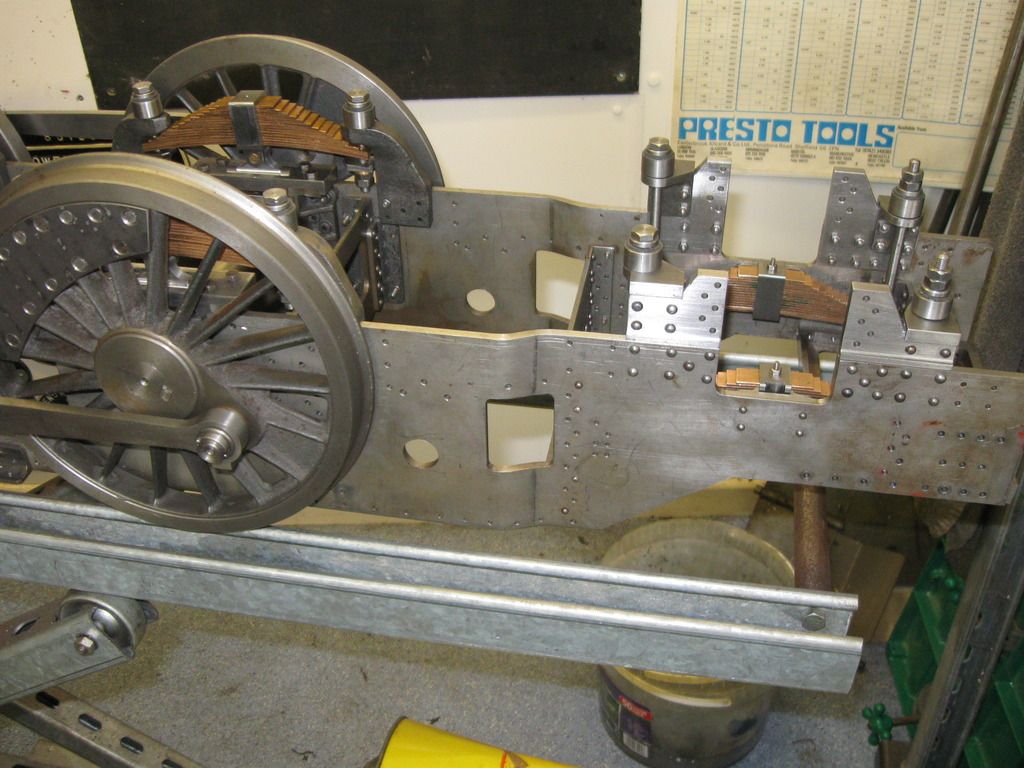
Rex have you still got the dimensions for the cut out size and position? Hi, as far as I can tell from the works drawings the cut out is 1 foot wide and 1 foot 6 inches tall. Its bottom edge is aligned with the bottom edge of the other cut outs in the frames. Its vertical centre line is 6 feet 8 inches from the rear end of the frames. Here is a picture of the cut out in my frames. I didn’t have the benefit of the works drawings when I made my frames so they may not be spot on but they are close enough for me.  Hope this helps.  |
|
|
|
Post by fostergp6nhp on Apr 21, 2015 21:12:03 GMT
Thank you very kindly sir.
|
|
|
|
Post by Rex Hanman on Apr 21, 2015 22:20:13 GMT
Most welcome!  |
|
|
|
Post by fostergp6nhp on Apr 30, 2015 12:31:32 GMT
Works have recommenced after a 25yr lay off! The buffing boxes for the rear buffer beam, cab steps and brackets, trailing hanging plates. The rear drag box thanks to Rex's help will have to be investigated regarding flipping and lowering the top tray and adding an angle iron above.
|
|
|
|
Post by fostergp6nhp on May 1, 2015 8:39:07 GMT
Front steps cut out and joggled, now to trim the rear hanging brackets to width then form the step plates from 22g tread plate.
|
|
|
|
Post by Rex Hanman on May 1, 2015 12:39:35 GMT
Well done Phil, any chance of some pics?
|
|
|
|
Post by fostergp6nhp on May 8, 2015 15:16:57 GMT
I will put up some pics when the step plates are done.
|
|
|
|
Post by fostergp6nhp on May 10, 2015 18:25:51 GMT
Well I have just found a possibly big problem. I fitted the rh cab steps to the outrigger bracket, it lines up fine with the top of the frames and the rear hanging plate also slips in. But the joggled stay bracket that goes between the steps and the frame fits but the holes are way out vertically. Somehow the holes for the bracket in my frames is 1/32" low to drawing as far as I can tell and the offset from the frames holes to the steps holes is 9/16", the overall thickness of the joggled stay bracket is only 1/2".
So which is wrong?
|
|
|
|
Post by fostergp6nhp on May 10, 2015 19:42:56 GMT
Well I have just been looking at photos borrowed from station road steam when he has had part built 51's, 2 of them have a bigger joggle in the step bracket and the other one has the as drawn joggle but the frames are not drilled and just like mine the holes would be lower than where the frame drawing would put them. I think my solution is to cut off the frame flange and bend a new flange and braze it on the top of the bracket to save making the whole lot again.
|
|
|
|
Post by Rex Hanman on May 10, 2015 21:24:23 GMT
Any chance of a picture or a link to the ones you refer to please?  |
|
|
|
Post by fostergp6nhp on May 11, 2015 6:12:54 GMT
The pics are in the archive section of station road steam, you just have to trawl down the list looking for the 51's.
|
|
|
|
Post by Rex Hanman on May 11, 2015 7:44:12 GMT
Nope! Just spent about half an hour trawling through the locomotives and projects section of the archives. There's hundreds! Can't find any pics of that bit. Must have missed them. Don't have time to go through again  |
|
|
|
Post by Deleted on May 11, 2015 8:12:48 GMT
|
|
|
|
Post by fostergp6nhp on May 11, 2015 14:26:59 GMT
That's one.
|
|