|
|
Post by havoc on Nov 5, 2006 20:09:56 GMT
This is a question that's bothering me since I learned about garratts:
How do they connect the valve gear on the engines to the reversing lever? Same would apply for a mallet I think.
I have been thinking about it, but cannot see it before me. And since there isn't any garratt around here I cannot go and have a look. The only thing I see on old pics are the control rods going to a small lever at the height of the bearing, but what happens then is what this question is about.
|
|
jones
Active Member
  Steam loco's and IC engines
Posts: 41
|
Post by jones on Nov 6, 2006 4:46:04 GMT
Havoc,
As I understand it they use a rotating square shaft with a matching square sleeve that can telescope in and out, with universal joints on each end. This transfers rotational movement that is not affected by the moving of either part of the loco. I was wondering this same thing for a long time and I thought that this was the only way they could do it. I am not 100 percent sure this is how they do it but this way would work.
Another way they could do it would be to use a power reverser, which only needs a pipe or hose to connect the parts of the loco.
Note: I don't know if any of this is correct. We'll hear from people who KNOW how they work, im sure.
Regards
Andrew
|
|
|
|
Post by Shawki Shlemon on Nov 6, 2006 9:04:48 GMT
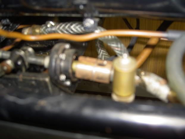
Hi As Jones says the method to transfer the movement between two non rigid parts is by using sliding male in a female control rod for axial movement and for side movement a universal will do the job .In my little Garratt (see my website) a lack of space problem which forced me to have two controls in the cab one for the front and one for the rear unit.The same principle is used on SHAY drive shafts. Tis photograph shows the front unit control connection between the boiler/cab frame and front unit on Little 5"G free lance Garratt.  |
|
|
|
Post by havoc on Nov 6, 2006 20:24:37 GMT
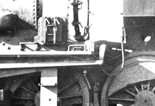
I understand the working of the parts you guys bring up, but I don't get it in this context. I added a scan (of a part of a picture from the "The NZR Garratt story")  Just below the running board, you see the end of the rod coming from the power reverser. It attaches to a small lever that can only connect to an axle perpendicular to the lenght. I agree it isn't clear if that axle is attached to the center section or to the enging section. The system you both mention works fine, but it works in the direction of the lenght, not the way this lever is actuated. This is what escapes me. Or they would have to convert from transversal motion to longitudinal and back. That at each side of the engine. Looks complicated and fragile to me for such an essential part of a loc. |
|
|
|
Post by Shawki Shlemon on Nov 7, 2006 6:52:15 GMT
Hi
I must admit that my model is free lance and it is my own design but similar mechanical arrangements are designed to transfer movement between two parts with relative movement to each other. Now to my model from the bolted housing which contains a screw shaft like a reverser going left to valve gear on front unit is conventional . From the housing to the right the sliding rods and universal allow the transfer of motion from cab to the reversing screw at all times .It works fine see it on my site .
|
|
|
|
Post by Shawki Shlemon on Nov 7, 2006 6:54:50 GMT
The last posting seasoned me . ;D What am I going to do with myself ?
|
|
|
|
Post by Phil Sutton on Nov 7, 2006 20:31:39 GMT
Add some mustard to the salt & vinegar and you'll be fine!! ;D
Phil
|
|
|
|
Post by Shawki Shlemon on Nov 8, 2006 7:59:06 GMT
I have to try that !!!! Thank you for the advice.
|
|
|
|
Post by davidimurray on Nov 8, 2006 10:25:24 GMT
Having spent lots of time working with NGG16 Garratts - I can tell you exactly how they work. The reverser is connected to a rod that runs the length of the boiler frame. At either end a shaft runs through to the centre of the engine - this is arranged directly above the engine/bogie pivot. A rod then then runs forward to a reversing shaft on the bogie - which runs the width of the engine to raise the lifting links. You can see the reversing shaft in this pic www.bangor.ac.uk/ml/whr/2002/aa-143bogie.jpgand the arm from the boiler cradle here www.bangor.ac.uk/ml/whr/2006/ar-143-291006-2.jpgOf course as it arranged about the pivot there is no need for extension of the arm. I might even have a diagram of the arrangement somewhere Cheers Dave |
|
|
|
Post by havoc on Nov 8, 2006 19:05:39 GMT
Thanks, that clears up a question that has been bothering me for a long time. Saved the pics for reference.
|
|