|
|
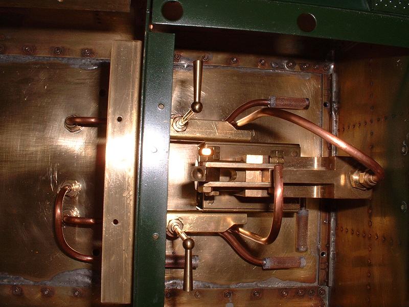
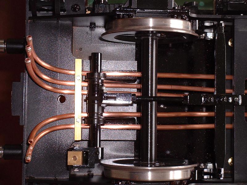
Post by peterdebeus on May 10, 2013 21:11:51 GMT
boiler just got its hydraulic certificate today! time to fire it up!
|
|
|
|
Post by peterdebeus on Jun 26, 2013 20:37:28 GMT
Fired the engine up for the first time last week.
Some small leaks and the fire grate wouldnt drop, so have to do some modifications i think.
Still problems with the motionwork, after i filled everhting with loads of oil it can turn quite smooth now but only 3/4 of a turn left and right, after that it makes a stop like hitting something, but not find anything till now, as far as i can see the motionwork runs free.....
maby its the axle pump or something...
Also i want to lock the nuts of the motionwork, what is the best way to do this? wire lock them?
|
|
|
|
Post by Deleted on Jun 26, 2013 22:15:09 GMT
Hello Chaps---------Here's an idea but not sure with the 9F if it can be done }----- remove both left and right crosshead pins, thus separating the piston rods from the connecting rods..... The 10-coupled wheelset should now rotate 360 degrees with no stopping......If it DOES rotate fully then that means either the R/H or L/H main piston is hitting an end cover......If it still DOESN'T rotate fully then the problem lies elsewhere---- as you say, perhaps the axlepump is over stroking ??-----so disconnect that next and try rotating-----
|
|
|
|
Post by RGR 60130 on Jun 26, 2013 23:43:19 GMT
Does it stop when in mid gear as well as full gear? - just trying to eliminate the valve rods hitting the ends of the valve chests.
Reg
|
|
|
|
Post by peterdebeus on Jun 27, 2013 7:05:53 GMT
Thanks a lot, Reg, i have already try to set it in mid gear, and it wouldt solve, or change anything. It still stops at exactly the same position as it did before. thanks for your help  First i will see if it stops near the and of the stroke of one of the cylinders, if they are half way when its blocks, i dont think it will be something with the cylinders?? Dous anyone know where to get a locomotive lifting table, so i can work on the underside? I was told by the one that ''part build'' the engine, that the valve timing was set roughtly and it has run on air, so i dont want to remove any parts of the motionwork when not needed. I have removed the fire grate its quite difficult to get your hands in there to remove the midle section without the other 2 parts falling down, shortened it with a few mm and re fitted it. cost me about 4 hours doing this but its working again!  |
|
leliev
Seasoned Member

Posts: 114
|
Post by leliev on Jun 28, 2013 6:22:30 GMT
If you push the engine, does it move freely? If not, check the coupling rods if they are equal.
|
|
|
|
Post by peterdebeus on Jun 28, 2013 9:23:30 GMT
I can turn the wheels 3/4 left and right, then it blocks... 3/4 of the stroke it runs ''free'' still a bit heavy but should be becouse all the motionwork is new.
Its a sudden stop, it dousnt clamp but its just hitting something.
|
|
|
|
Post by peterdebeus on Jun 28, 2013 10:11:07 GMT
I have another question, The water lines that run underneed the tender are 1 feed lines and one return. And one seperate pressure line from the tender water pump with a seperate conection and check valve fitted on the loco so that should be fine. There are also 2 conections on the loco so that should be ok  haha the first conection (feed line) splits up, one line with a valve to the injector, and one to the axle pump. the second conection (return) also splits, one line is the return from the axle pump. And the other one also a valve with a line to one of the injectors. I have never seen it like that, most models i see have one or 2 lines running directly to the injectors and one to the axle pump. Dous any one have tested the origional system like it came from modelworks or do i have to change this? The conections are quite high directly under the footplate, and the lines are underneed the tender. If i want to couple the locomotive and tender the flexible hoses have to go all the way up. And as there is almost no space between the loco and tender you have to make a lot of strange bends. Maby someone has some pictures of how they made those conections, or how they changed it? On the link below you can see the conections on my loco: www.stationroadsteam.co.uk/stock%20pages/5713/pages/5713-%20(31).htmHere you can see how low the conections on the tender are, and how much higher on the loco. www.stationroadsteam.co.uk/stock%20pages/5713/pages/5713-%20(14).htmJust let me know what you think  |
|
|
|
Post by RGR 60130 on Jun 28, 2013 13:26:51 GMT
Peter, The pipe runs look like a bit of a nightmare! I found a clip of a 9F on youtube that shows the more conventional arrangement with the connections below the level of the tender here: www.youtube.com/watch?v=JZhVxyhX-IQOn the full size locomotive the connections are all at this low level. Reg |
|
|
|
Post by RGR 60130 on Jun 28, 2013 13:32:41 GMT
This is the left hand side water connection on Evening Star.  |
|
|
|
Post by peterdebeus on Jun 28, 2013 13:49:41 GMT
Thank you Reg,
Yes it is a big mess and after looking at different loco's during some events i have never seen something like this.
Thats why i was thinking about changing this to the ''conventional'' system and fit 2 feed lines
to the injectors and one extra line to the axle pump.
Or i make just one conection line and fit it with an Y piece underneed the loco.
Not sure if i get enough water trough because both injectors will get water when opening the valve.
And i have to make that valve on the tender ofcoars.
I didnt get the injectors that came with the engine working, probably because they just dont get enough water.
|
|
jma1009
Elder Statesman
  
Posts: 5,917
|
Post by jma1009 on Jun 28, 2013 19:22:34 GMT
hi peter,
we have discussed the unsatisfactory (cheap) arrangement of pipework on modelworks locos before. you are quite correct to be suspicious of this arrangement which IMHO is far from ideal.
each injector should have its own feed pipe, and filter (unless there is a really big well tank type filter). there seems to a suggestion that on the modelworks locos the injector feed is taken from the tender handpump feed pipe and through the tender handpump which is very bad practice. the axlepump should also have a separate feed pipe and return pipe for the bypass valve.
so quite a few alterations required im afraid.
virtually all injector failures are caused by incorrect pipework and and their associated fittings.
cheers,
julian
|
|
|
|
Post by Deleted on Jun 28, 2013 19:49:42 GMT
Hi Peter These photos show how I modified my Modelworks BR1A tender to have 4 separate filtered feeds for the 2 injectors, handpump and axlepump, and a return for the axlepump bypass. Note the 90 degree valves for the injector feeds, which are very convenient.   Regards, John |
|
|
|
Post by peterdebeus on Jun 29, 2013 14:39:22 GMT
Thank you verry much, now i know what to do, and how to change this, and hopefully it will be working when i fire it next time.
Can somebody see on my pictures if this are the origional injectors that came with the kit, and are they ok?
Mister John, your pipework looks like a real piece of art!
|
|
jma1009
Elder Statesman
  
Posts: 5,917
|
Post by jma1009 on Jun 29, 2013 20:42:58 GMT
the injectors look like those made for the trade by the late john cashmore. i have no idea whether john supplied modelworks.
cheers,
julian
|
|
|
|
Post by Deleted on Jun 29, 2013 20:46:14 GMT
Hello Chaps----------- does a 5"gauge 9F really need a by-pass system ?? Can't you manage on 2 live steam injectors and a hand pump ?? (Would simplify the pipework if nothing else)
|
|
|
|
Post by peterdebeus on Jun 30, 2013 11:06:10 GMT
You mean scrap the axle pump and use 2 injectors and the hand pump only?
|
|
|
|
Post by Deleted on Jun 30, 2013 16:37:38 GMT
Hi Peter
I would be inclined to keep the axle pump if possible, at least until you have more experience of driving the engine and you are sure that both injectors are reliable. When I started driving my Britannia I left the axle pump on all the time which meant that I only had to use the injectors occasionally while stationary. I would be happy now to rely on my injectors, but the axle pump is very useful when you are learning to drive.
Regards, John
|
|
|
|
Post by Deleted on Jun 30, 2013 18:48:39 GMT
Hello Chaps ------- No, I wasn't advocating scrapping the system as such, just querying the actual need for it in the first place on the 9F...However I agree with JJ re}--- being a Learner Driver / Fireman, you'll have your work cut-out initially so it will be of help..Besides, the momentum of a 5" 9F is more than enough to keep a what, 3/4" ram ?? pump system circulating the water with no adverse effects on it's hauling power....You can always disconnect at a later date if you want to anyway...
|
|
|
|
Post by peterdebeus on Jun 30, 2013 21:50:05 GMT
Ok thanks for the advice! i will keep the axle pump and see how it will work out, disconecting the axle pump is something i can always still do. I have the advantage to have a rolling road, so i can practice the firing without actualy driving the engine. Some pictures to give you an idea how it looks at the moment. click to enlarge! Complete engine ready for the first tests on the rolling road.  back in the ´´workshop´´  some detail pictures of the motionwork, i´m sorry, im not a photographer    after a 3 hour fight i won! its back in there   i was wondering if this is the right position for the blower pipe? i see so many different systems...  |
|