|
|
Post by Roger on Jan 20, 2019 19:19:51 GMT
Hi Roger, Nice to see the M2.5 being "Floated" in there, matey !!.............I think your Avatar should now be the Mona Liza, as this latest job is surely a work of Art ?? I won't be at Ally Pally but look forwards to seeing you again up here in Shropshire this Spring /Summer ??.....Try and bring Julian this time ?? Hopefully this year will be a little less hectic than the last. We've had three funerals in the family this year which has left us reeling. We're looking forward to happier times and a few pleasant excursions. Watch this space! |
|
|
|
Post by delaplume on Jan 20, 2019 19:35:36 GMT
Hi Roger, Nice to see the M2.5 being "Floated" in there, matey !!.............I think your Avatar should now be the Mona Liza, as this latest job is surely a work of Art ?? I won't be at Ally Pally but look forwards to seeing you again up here in Shropshire this Spring /Summer ??.....Try and bring Julian this time ?? Hopefully this year will be a little less hectic than the last. We've had three funerals in the family this year which has left us reeling. We're looking forward to happier times and a few pleasant excursions. Watch this space! If you want any overnight accomodation then do let me know--------there's plenty along the SVR route.. |
|
|
|
Post by Roger on Jan 20, 2019 19:53:41 GMT
The hand brake has a slotted link on the bottom which is connected to the hand brake with a rod. This is the link part which will be Silver Soldered to the rod. The outside was machined with a 5.5mm cutter and the slot is done with a 2.4mm slot drill. 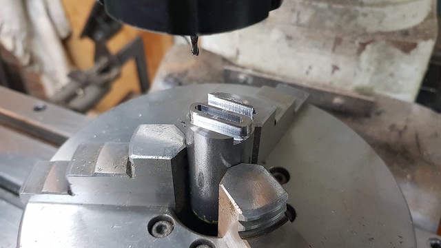 20190120_180600 20190120_180600 by Anne Froud, on Flickr This is how it looks after parting off...  20190120_183210 20190120_183210 by Anne Froud, on Flickr ... and tidied up with needle files.  20190120_194840 20190120_194840 by Anne Froud, on Flickr |
|
|
|
Post by Roger on Jan 21, 2019 22:17:34 GMT
This is going to be the top forked piece on the end of the round hand brake rod. It's being machined from 10mm Free Cutting Mild Steel bar set far enough from the chuck to allow the ER32 collet to miss the jaws. Obviously this means it's not that rigid a setup, so the order and style of machining needs to reflect that. The bar was clocked as accurately as possible to the centre of rotation of the rotary table and the angle set to zero. Here I've measured the diameter of the stock with a micrometer, locked the quill with the cutter touching and then set the Z-axis DRO to the radius. The centre of rotation is zero on the CAM model.  20190121_104024 20190121_104024 by Anne Froud, on Flickr The first two sides and square end were machined first with a 4mm 4-flute cutter... 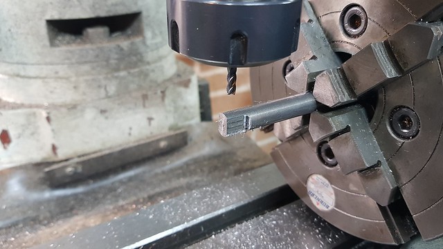 20190121_110257 20190121_110257 by Anne Froud, on Flickr ... then turned through 90 degrees and the radius end done. 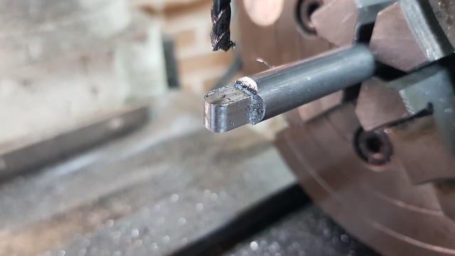 20190121_134958 20190121_134958 by Anne Froud, on Flickr Then the pivot hole was drilled and the table turned back to zero to machine the slot with a 2.5mm 2-flute. 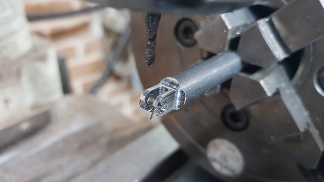 20190121_154536 20190121_154536 by Anne Froud, on Flickr Then it was back to the 4mm cutter to cut the neck on both sides. This wasn't done before because I wanted it to be as rigid as possible while machining the end and the slot.  20190121_160535 20190121_160535 by Anne Froud, on Flickr The same program was used to machine the neck at 90 degrees. 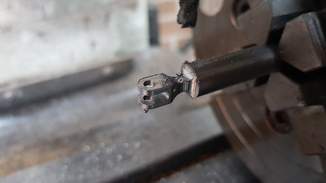 20190121_162635 20190121_162635 by Anne Froud, on Flickr It was then parted off, tidied up with a file and the 2.5mm location for the rod drilled. It was just possible to use the wobbler on the exposed curved part. 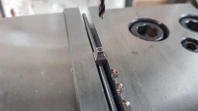 20190121_171857 20190121_171857 by Anne Froud, on Flickr The rod was machined from 3mm Silver Steel with 2.5mm diameter registration pieces turned on the ends 2mm long. The toolmaker's clamp just stops the flux from boiling and forcing the ends apart.  20190121_201128 20190121_201128 by Anne Froud, on Flickr The assembly was straightened and tidied up with needle files. It acquired a bit of a bend, but that was easily straightened out in the vice with careful application of a mallet. I took care to cool the whole thing as slowly as possible. I was mindful of the fact that Silver Steel had the potential to be glass hard if it cooled rapidly. As it happens, it feels pretty soft. You'll only be able to see the bottom of this, and 1501 does have a round rod, hence that attention to detail I don't normally bother with between the frames. 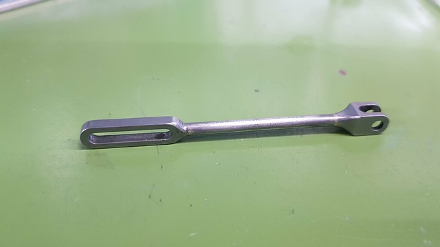 20190121_211124 20190121_211124 by Anne Froud, on Flickr |
|
|
|
Post by Roger on Jan 23, 2019 19:51:29 GMT
This is the arm connecting the hand brake to the brake shaft via the slotted link. It's been roughed out with an 8mm ripper and I've left it so you can see how it normally is before clearing away the swarf. Clearly it's been re-cutting swarf, but this doesn't matter since it's not a finishing cut. 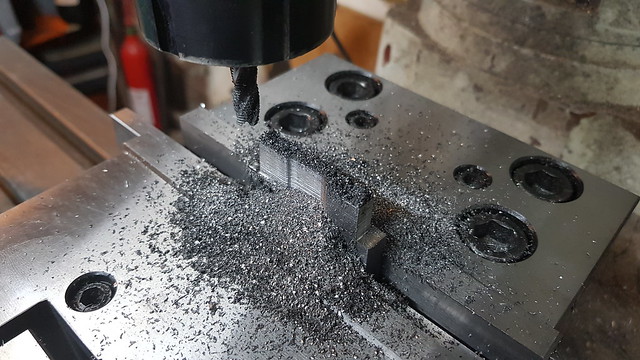 20190122_173910 20190122_173910 by Anne Froud, on Flickr The profile was finished with a 4mm cutter and the slot made with a long series 3mm 4-flute cutter. Again, the top of the slot was cleared away so the cutter could read down far enough. 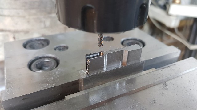 20190122_213405 20190122_213405 by Anne Froud, on Flickr It was a bit short to hold in the vice, so I decided to clamp it to a parallel instead. It's not ideal since it's not being held as tightly as I'd like and the cutter has to protrude a long way, even with the edge clamp. So it was a case of softly softly with 0.25mm cuts and 10mm/min feedrate so it didn't end in tears. 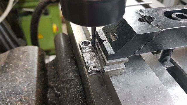 20190123_085717 20190123_085717 by Anne Froud, on Flickr Like the last one, I left 1mm of material to support it for the finishing cuts which is more than adequate.  20190123_162805 20190123_162805 by Anne Froud, on Flickr The finish isn't marvellous, but...  20190123_163743 20190123_163743 by Anne Froud, on Flickr .... a little work with needle files and it cleaned up easily enough. It's an awkward shape with a joggle so that it lines up with the brake handle which is in the correct scale position.  20190123_193838 20190123_193838 by Anne Froud, on Flickr |
|
JonL
Elder Statesman
   WWSME (Wiltshire)
Posts: 2,993
|
Post by JonL on Jan 23, 2019 20:27:43 GMT
The finish you get with your needle files is excellent.
|
|
|
|
Post by Roger on Jan 23, 2019 20:53:51 GMT
The finish you get with your needle files is excellent. I found some superb Diamond Needle files at a show a few years ago, and they are the secret. Sadly I can't find any more, most are garbage, way too coarse and the diamond particles tear off. I may find some in a professional tool catalogue such as J&L Industrial (MSC) when I need to replace them. |
|
|
|
Post by Roger on Jan 24, 2019 20:39:43 GMT
There are a pair of arms that connect the drain cock lever in the cab to the pull rod along the bottom of the frame. This is going to be the one on the outside.  20190124_084136 20190124_084136 by Anne Froud, on Flickr I've gone quite a bit deeper than the required size of the arm so that there's plenty of clearance for the other machining operations.  20190124_085045 20190124_085045 by Anne Froud, on Flickr The stock was sawn off to gain access to the part. This is the roughing operation to clean up the outside joggled face...  20190124_104253 20190124_104253 by Anne Froud, on Flickr ... which was then finished and the slot machined with a 1.5mm cutter.  20190124_121843 20190124_121843 by Anne Froud, on Flickr 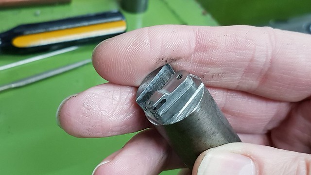 20190124_121947 20190124_121947 by Anne Froud, on Flickr This is a wobbly video of parting it off. The saddle was locked because it's on the edge of the stock and the part so it might move. I don't often lock it, but this time it looked like it might be a problem. You can see that an intermittent cut is no problem for Carbide tooling, contrary to what is often stated. The key here is to use the lowest power feed rate, go slowly and use flooded neat cutting oil.  20190124_122843 20190124_122843 by Anne Froud, on Flickr The surface isn't flat of course, it never is with an intermittent cut. I've left 0.1mm to tidy that up with needle files... 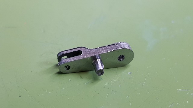 20190124_193641 20190124_193641 by Anne Froud, on Flickr ... so it looks like this.  20190124_201859 20190124_201859 by Anne Froud, on Flickr It's quite small, but it's visible so I thought I'd make it as elegant as I could. This one is going to be either Silver Soldered or Loctited to the shaft permanently. The inside one will be held on with a hex and a nut. 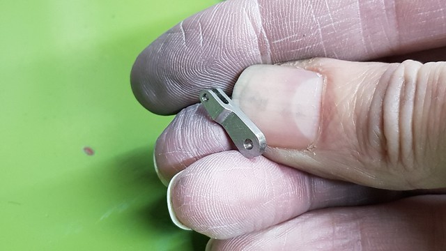 20190124_201926 20190124_201926 by Anne Froud, on Flickr |
|
|
|
Post by Roger on Jan 25, 2019 14:56:22 GMT
This is the inside arm for the drain cocks, made in the same manner as the outside one shown recently. However, this arm needs to be removable but the shaft is only 2.5mm diameter. The solution I've chosen is to machine a rounded hex on the shaft and use an M2 nut to hold it on. This is the mating hole in the arm to suit. The hex is 2mm AF so for it to be any sort of hexagonal shape, the corner radii need to be pretty small. Here I'm using a 0.5mm PCB burr rather than a milling cutter intended for Steel. The geometry it totally wrong and it's way too long and flexible really, but at just over £1 each, you can afford to break one or two. As it happens, this machined without any such problems because I took it very gently indeed. I'm working today, so it didn't matter how long it took. I don't like thrashing the large spindle or making a lot of noise, so I ran it at only 2500RPM using 50 micron (2 thou) cuts and 3mm/min feed rate. That took three hours gently turning it to dust. I drilled a 1.8mm pilot hole first. Had I swapped to the high speed spindle I could probably have done it in half an hour, but there seemed little point since I wasn't in a hurry.  20190125_140452 20190125_140452 by Anne Froud, on Flickr Anyway, this is how it came out after tidying up. 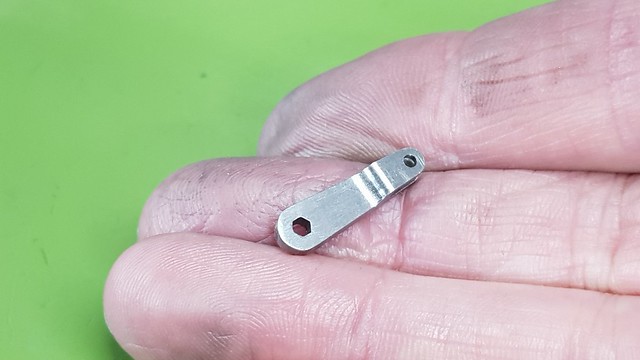 20190125_144413 20190125_144413 by Anne Froud, on Flickr |
|
|
|
Post by steamer5 on Jan 25, 2019 22:01:16 GMT
Hi Rodger,
This is starting to encroach into watch making! Very nice!
Have you thought of rotary broaching hexagonal holes like this?
Cheers Kerrin
|
|
|
|
Post by Roger on Jan 25, 2019 22:06:01 GMT
Hi Rodger, This is starting to encroach into watch making! Very nice! Have you thought of rotary broaching hexagonal holes like this? Cheers Kerrin Hi Kerrin, I think it's way too small for a rotary broach. You could make a hexagonal conventional broach I suppose, but it's probably not something I'd use again. Glad you like it, these things are fun to attempt, just to push the boundaries. |
|
JonL
Elder Statesman
   WWSME (Wiltshire)
Posts: 2,993
|
Post by JonL on Jan 25, 2019 22:10:25 GMT
I want to have a crack with a rotary broach at some point, they look fascinating.
|
|
|
|
Post by steamer5 on Jan 25, 2019 22:12:53 GMT
Hi Rodger,
There are several builds for rotary broaching tools on HMEM, a couple of the guys were making broaches down to the 2mm size which is why I asked. I guess at that size you would need to take it slow & steady.
Cheers Kerrin
|
|
|
|
Post by Roger on Jan 25, 2019 22:14:44 GMT
Another day, another rod, this time it's the hanging link that supports the long drain cock pull rod just behind the cylinders.  20190123_192442 20190123_192442 by Anne Froud, on Flickr Again I've chosen to make this from a piece of 4mm thick Gauge Plate because it's so slender. 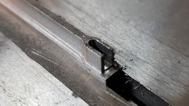 20190123_200446 20190123_200446 by Anne Froud, on Flickr The scrap or material isn't really big enough to hold so I've welded it to the end of a piece of Mild Steel strip.  20190123_214034 20190123_214034 by Anne Froud, on Flickr Yeah, it's a mess, but it's not important. I had to heat it up to a dull Red and then bury it in a sandwich between two insulating tiles and seal the edges so it would cool down slowly and lose the hardness from the rapid cooling it got when being welded.  20190123_214059 20190123_214059 by Anne Froud, on Flickr The same technique was uses to machine most of the way round, leaving enough to support it.  20190125_193600 20190125_193600 by Anne Froud, on Flickr It's machined reasonable nicely considering it's not the easiest of materials to work with.  20190125_193714 20190125_193714 by Anne Froud, on Flickr Anyway, it ended up like this after half an hour with a set of needle files. 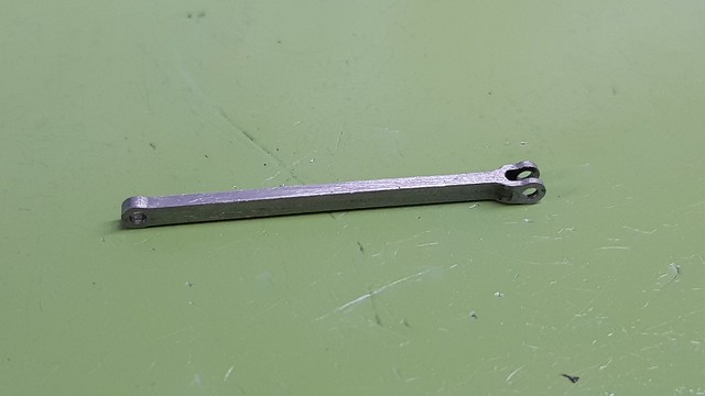 20190125_215842 20190125_215842 by Anne Froud, on Flickr And in case you were wondering how big that is... 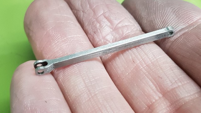 20190125_215921 20190125_215921 by Anne Froud, on Flickr |
|
|
|
Post by Roger on Jan 25, 2019 22:16:23 GMT
Hi Rodger, There are several builds for rotary broaching tools on HMEM, a couple of the guys were making broaches down to the 2mm size which is why I asked. I guess at that size you would need to take it slow & steady. Cheers Kerrin That's pretty small. For me there's little point in making a tool for something I can just program and machine. They're an interesting, if obsolete, tool though. |
|
|
|
Post by andyhigham on Jan 25, 2019 22:21:58 GMT
I suppose if you needed sharp corners in the hexagonal hole, you could mill it out then grind a section of allen key and press it through
|
|
|
|
Post by Roger on Jan 26, 2019 8:09:26 GMT
I suppose if you needed sharp corners in the hexagonal hole, you could mill it out then grind a section of allen key and press it through Hi Andy, That's one way but I'd probably machine a scrap of Silver Steel to the desired size and harden and temper it so it was the exact size. I'd want to machine the hex using the Allen key as a gauge otherwise since I think they are slightly under the nominal size. In reality, you don't need sharp corners, only a decent length of the flat part of the hex for it to provide a good location. Adding a small radius to the corner allows you to have a slightly larger AF size too if you want to maximise that. |
|
|
|
Post by yorkshireman on Jan 26, 2019 19:37:43 GMT
|
|
|
|
Post by Roger on Jan 26, 2019 22:17:42 GMT
Today I'm making another of the tiny connecting rods for the drain cock mechanism. Here I've already done the edge machining with the slots, and this arrangement is to not only hold the part flat onto the parallels, but to also clamp the parallels onto the base of the vice. The problem is that the piece I'm holding is very short, so short that it's beyond the base of the vice. That means the parallels can't provide any upwards force. 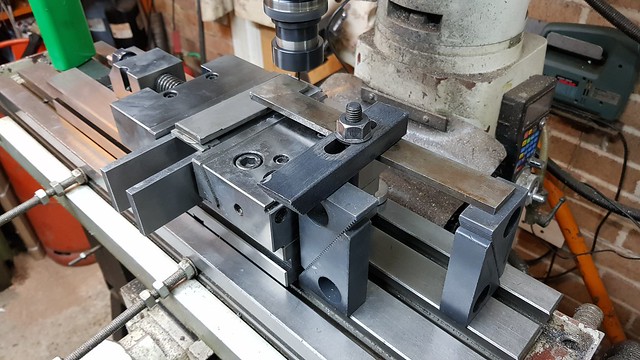 20190126_121458 20190126_121458 by Anne Froud, on Flickr So the LH end of the flat bar running parallel with the vice jaws rests on a piece that's on top of the parallels while the RH end presses on the workpiece.  20190126_121507 20190126_121507 by Anne Froud, on Flickr Again, the centre section is left to hold it in place while machining all round. That's 0.75mm thick in this case since it's Gauge Plate and pretty tough. 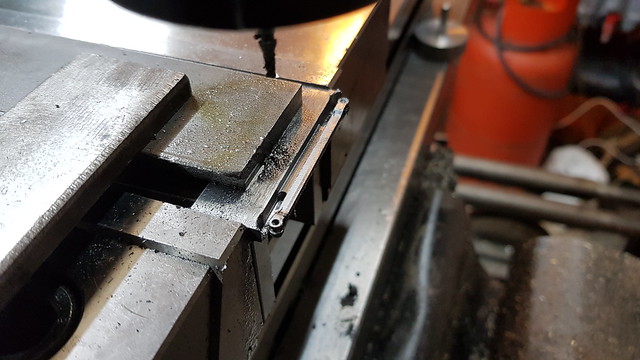 20190126_191036 20190126_191036 by Anne Froud, on Flickr I've not mentioned how I finish these in any detail, so I thought it's about time I explained that. Here I've roughly filed off the bulk of the sawn section on the right.  20190126_200725 20190126_200725 by Anne Froud, on Flickr The next step is to use a fairly fine flat needle file and draw file the highest area using a slightly bottom left to upper right stroke. The angle has been set to catch the light so I can see the file marks on each stroke.  20190126_200810 20190126_200810 by Anne Froud, on Flickr The next pass is done with a slight bottom right to top left strok, again watching it like a hawk to see where the file lines are.  20190126_200921 20190126_200921 by Anne Froud, on Flickr Then it's just a matter of rinse and repeat on the highest areas until it all cleans up across the width all the way up. Then it's time for one fine pass directly up and down to finish it off. I hold the file between the first finger and thumb of both hands.  20190126_205308 20190126_205308 by Anne Froud, on Flickr If does my back in having to bend over the vice, so I bring the vice up really high so I can squint at it over the top of my glasses. It's at a jaunty angle because I find that suits the high position to my liking. I don't claim any of this as my idea, except for the 'Vice on a stick' of coarse which I highly recommend for all fine finishing work. I use cereal packet cardboard folded in half as my soft jaws.  20190126_205323 20190126_205323 by Anne Froud, on Flickr Anyway, this is the result... 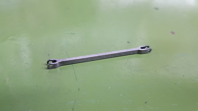 20190126_212915 20190126_212915 by Anne Froud, on Flickr ... and yes, it's pretty small.  20190126_212934 20190126_212934 by Anne Froud, on Flickr |
|
|
|
Post by 92220 on Jan 27, 2019 9:08:29 GMT
Lovely job Roger. I'm just glad my drain cocks are steam operated!!
Bob.
|
|