|
|
Post by delaplume on Jan 15, 2019 16:25:52 GMT
Hello everyone,
I can't find that video about clupet rings....can someone put a link up please ??...ta.
|
|
|
|
Post by delaplume on Jan 15, 2019 16:30:49 GMT
With regards to quality etc.....How's that song go again?---------------------
"It's not what you do but the way that you do it, that's what gets results !!"...
|
|
weary
Part of the e-furniture

Posts: 302
|
Post by weary on Jan 15, 2019 16:56:00 GMT
How to make clupet rings clcky-linky-thingy. or, search on youtube ... How to make clupet piston rings Very interesting video. Apologies for the (generally) off-topic posting but seems best to go with it! Regards, Phil |
|
|
|
Post by delaplume on Jan 15, 2019 17:00:10 GMT
OK------- found it !!
Did you notice how his Right thumb acquired a bandage about halfway through ??......Hmm.
Having now watched it a few times I'm not sure if there is any distinct advantage of this type over two or more seperate "thin"rings, fitted within the same total width that the Clupet ring occupies..?
The LMS had piston valve ring leaking problems on the Royal Scots...........I believe this was found to be caused by the ring being too long in relation to it's width and therefore couldn't "Float" adequately as wear took place on the piston rod bushes........By introducing much thinner rings over the same width the whole assembly was allowed to adjust itself to wear and still maintain sealing.....
I've seen a similar approach to Turbine shaft sealing....
|
|
|
|
Post by Roger on Jan 15, 2019 19:18:52 GMT
How to make clupet rings clcky-linky-thingy. or, search on youtube ... How to make clupet piston rings Very interesting video. Apologies for the (generally) off-topic posting but seems best to go with it! Regards, Phil Many thanks for posting this Phil, that's how I pictured it being done from the descriptions I'd read. This is the sort of openness I'd like to see throughout Model Engineering. There's no magic in any of these things, just a few basic things you need to know before you can do it yourself. It's frustrating when people try to keep these things to themselves when they ought to be owned by the community. Pressure gauges and injectors have had 'secrecy' issues in the past, and all the information about those still doesn't appear to be in the public domain. |
|
|
|
Post by Roger on Jan 15, 2019 19:22:52 GMT
OK------- found it !! Did you notice how his Right thumb acquired a bandage about halfway through ??......Hmm. Having now watched it a few times I'm not sure if there is any distinct advantage of this type over two or more seperate "thin"rings, fitted within the same total width that the Clupet ring occupies..? The LMS had piston valve ring leaking problems on the Royal Scots...........I believe this was found to be caused by the ring being too long in relation to it's width and therefore couldn't "Float" adequately as wear took place on the piston rod bushes........By introducing much thinner rings over the same width the whole assembly was allowed to adjust itself to wear and still maintain sealing..... I've seen a similar approach to Turbine shaft sealing.... Hi Alan, The advantage is surely that you don't need to pin to separate rings to prevent the gaps becoming aligned? Other than that, I don't really see another. The problem with Clupet rings is that I doubt you could make them for piston valves in ME sizes because of the issue of them breaking when you have to fold them back over each other. Having said that, you'd be able to do it with Flourosint rings. I might try that one day. |
|
|
|
Post by Cro on Jan 15, 2019 20:01:16 GMT
OK------- found it !! Did you notice how his Right thumb acquired a bandage about halfway through ??......Hmm. A Duke of Gloucester bit him!! Nothing to do with the rings. |
|
|
|
Post by David on Jan 15, 2019 21:57:09 GMT
Of course the Chinese can make precision machinery as well as anyone else - all their space and military projects must require decent engineering.
But most of us model engineers demand prices as low as possible which leads to the obvious result.
I was lucky with my lathe, it seems ok if not great. There are loose spots and tight spots and it needs some aligning done that I've never got around to. It's missing a piece of carriage rack on gap that would be useful to have. But it's capable of work smaller lathes would need absurd modifications to handle. My milling machine was a disaster - the fitting on it was atrocious and took me multiple attempts and about 50% of the purchase price again to fix due to the requirement for a complete gearbox rebuild.
Tormach is suffering quite badly from this. Their machines cost an embarrassing amount of money but their quality is pretty ordinary if you read various people's experiences. Mine arrived with the electronics cabinet almost complete sheared off which I guess was a shipping rather than manufacturing problem. But there is a YouTube Video showing how their original RapidTurn lathe spindles were all out of spec originally.
I find it hard to believe any of those live steam models are built differently depending on who puts their brand on them. And to have a complete loco built for the prices you see in the magazines doesn't make me think any of them would be masterpieces. They may no longer have a few 1/16 holes for steam ports and their cylinder liners may now be more concentric, but you're still not paying for high quality work.
However I have never seen one and perhaps the production models are wonders of moderns manufacturing.
|
|
|
|
Post by Roger on Jan 19, 2019 21:43:13 GMT
This is the lever connecting the Steam brake to the brake rod being made by the method originally described by Pault for the connecting rods. This is the process... Roughing the profile with an 8mm Ripper... 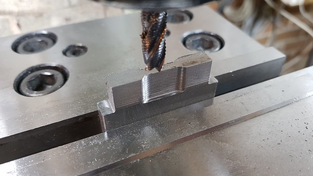 20190119_111142 20190119_111142 by Anne Froud, on Flickr ... then finished with a 5.5mm three flute. 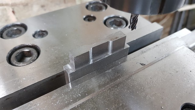 20190119_150108 20190119_150108 by Anne Froud, on Flickr The slot is too deep to reach with the 4mm cutter, so the top 1.5mm was opened out first since that part will be machined away in the next operation. 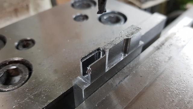 20190119_162630 20190119_162630 by Anne Froud, on Flickr Then it was set on its side, the extra clamp is to make sure it can't flip up since it's only on the edge of the vice. As it happens, I tried tapping it up and down with a mallet and it's pretty firm since the vice is a quality one. 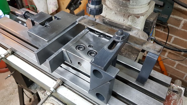 20190119_174146 20190119_174146 by Anne Froud, on Flickr The 8mm hole was roughed out using a pocketing technique so that it's lined up accurately. 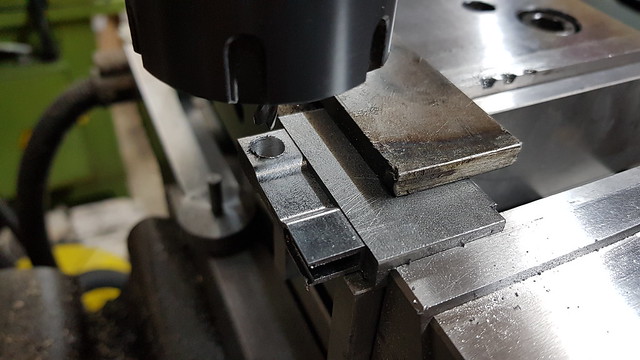 20190119_174155 20190119_174155 by Anne Froud, on Flickr The idea was to guide the reamer which was held much higher up with the table dropped. 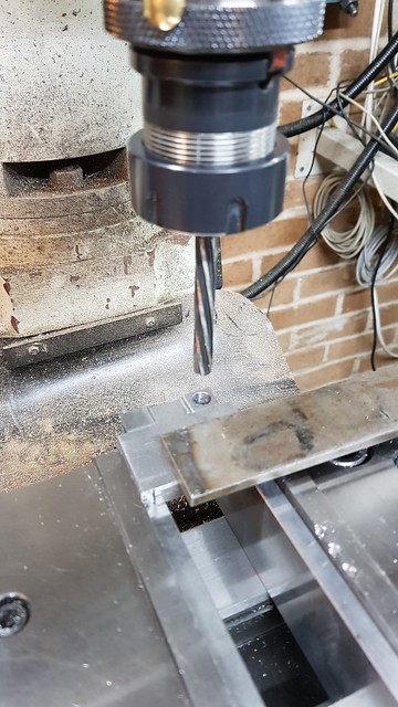 20190119_174646 20190119_174646 by Anne Froud, on Flickr The spotting drill was held in a collet and the quill lock slightly tightened so that the centre for the pin was in the right place. 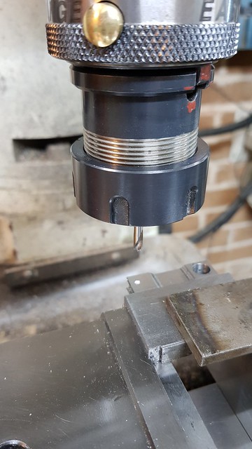 20190119_174948 20190119_174948 by Anne Froud, on Flickr The profile was cut with a 2.5mm two flute, cutting around all of the perimeter with the exception of the central section so it's held in place. 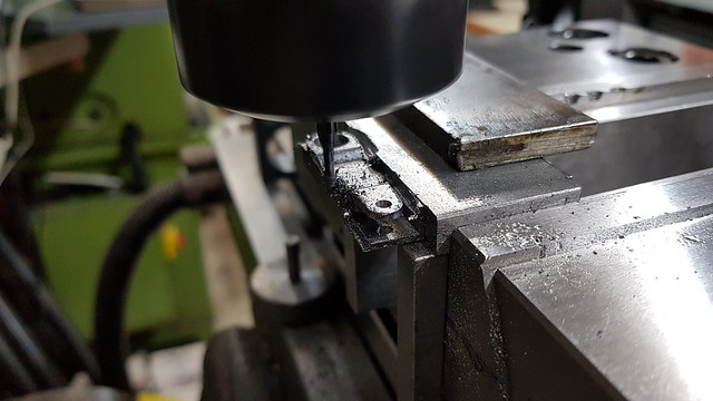 20190119_182020 20190119_182020 by Anne Froud, on Flickr Finally, the remaining part holding it on was reduced from 3mm thick to just 1mm... 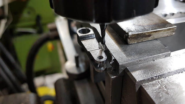 20190119_204052 20190119_204052 by Anne Froud, on Flickr ... so it looked like this. 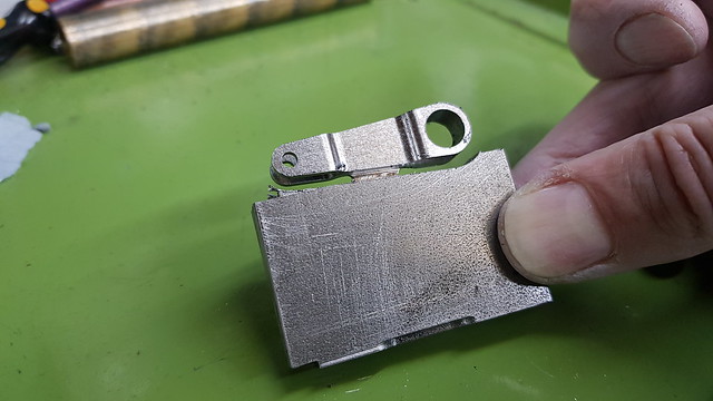 20190119_204635 20190119_204635 by Anne Froud, on Flickr That left just the small sawn portion to be tidied up with needle files... 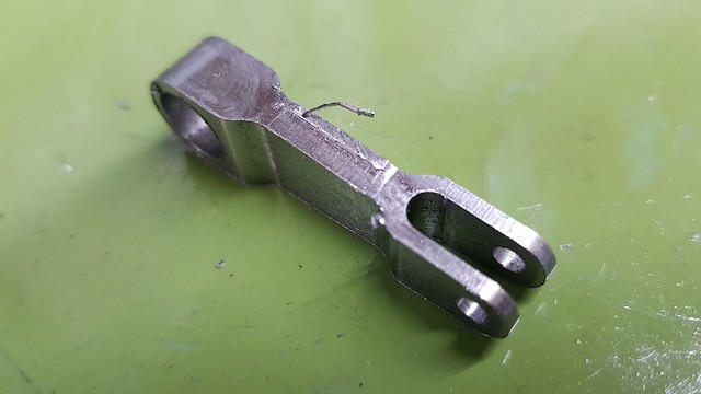 20190119_205246 20190119_205246 by Anne Froud, on Flickr ... so it looks like this.  20190119_211850 20190119_211850 by Anne Froud, on Flickr |
|
|
|
Post by andyhigham on Jan 19, 2019 23:25:23 GMT
Phew, I was getting withdrawal symptoms after this thread dropped to page 2
|
|
|
|
Post by yorkshireman on Jan 20, 2019 8:03:15 GMT
This page would be more impressive, really, if only the methods of LBSC or Martin Evans were used.
Roger should prove for once, that he can make such part purely using traditional, manual methods.
Johannes
|
|
Lisa
Statesman
 
Posts: 806 
|
Post by Lisa on Jan 20, 2019 8:31:42 GMT
This page would be more impressive, really, if only the methods of LBSC or Martin Evans were used. Roger should prove for once, that he can make such part purely using traditional, manual methods. Johannes We'll all just read your loco building thread for that Johannes... uh, where is it? Roger certainly has nothing to prove, he does things his way, as do we all. |
|
|
|
Post by Roger on Jan 20, 2019 8:49:34 GMT
This page would be more impressive, really, if only the methods of LBSC or Martin Evans were used. Roger should prove for once, that he can make such part purely using traditional, manual methods. Johannes Hi Johannes, I've been there and done that during my Engineering apprenticeship with General Motors and all the time until I converted my mill to CNC. Please don't assume that because I choose to make things using CNC that I can't and haven't made similar things the hard way. |
|
pault
Elder Statesman
  
Posts: 1,502
|
Post by pault on Jan 20, 2019 11:48:50 GMT
Interestingly it's a common misconception that CNC makes everything easy. You have all the same problems that manual machining has, but with none of the feed back you get from turning handles. Add in having to sometimes "fool" a program or bit of software to do what you want it to can make something that would be relativly simple on a manual machine quite tricky on a CNC machime. But we all love challenges so it's all part of the fun.
|
|
|
|
Post by ettingtonliam on Jan 20, 2019 15:33:29 GMT
This page would be more impressive, really, if only the methods of LBSC or Martin Evans were used. Roger should prove for once, that he can make such part purely using traditional, manual methods. Johannes I think you'll find there are only a few Luddites like me who do it the old way these days. I have the utmost admiration for Roger and his methods, and his results are far superior to mine. I have expressed doubts to him about the time his methods take, but he's answered that, if you choose to read the thread. I use the excuse that because I'm modelling 'Locomotion' which was built in 1825, by blacksmiths, and maintained by blacksmiths, that my methods are appropriate to the prototype. This isn't belittling blacksmiths either, 'Locomotion' was state of the art at the time. What are you building Johannes? |
|
|
|
Post by Rex Hanman on Jan 20, 2019 16:19:57 GMT
Roger should prove for once, that he can make such part purely using traditional, manual methods. Johannes Why?? |
|
uuu
Elder Statesman
   your message here...
Posts: 2,864
|
Post by uuu on Jan 20, 2019 16:30:57 GMT
Please can we transfer this discussion to a more appropriate medium. Pen and paper (absorbent variety preferred) is suggested.
Wilf
|
|
|
|
Post by ettingtonliam on Jan 20, 2019 16:44:34 GMT
Chisel, hammer, block of stone?
|
|
|
|
Post by Roger on Jan 20, 2019 17:02:03 GMT
I had to wait for the 2mm section Silicone 'O' ring to arrive before machining the piston. That's because I wanted to test the fit in the cylinder to assess the friction. In the end I settled on 5% compression which gives a light nip with very little force required to move the piston. Here I'm adding the cross hole for the 1mm section 'O' ring cord that's to become the spring for the ball valve. In fact it measures 1.12mm diameter as best I can measure, so the hole has ended up as 1.2mm before being able to get it in the hole. You can see I'm holding with in a two part collet which is actually the swaging tool I made for 4mm copper pipe. The piston is threaded tightly onto the piston rod. It's an M3.5 thread, readily available but not normally used. (except for those screws holding the face plates onto UK socket fascias.) 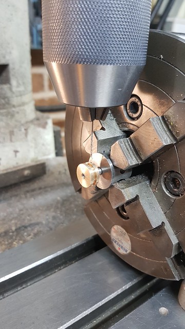 20190120_115120 20190120_115120 by Anne Froud, on Flickr This is the M2.5 thread going in for the grub screw that stops the ball from falling out. The piston is made from Leaded Bronze. 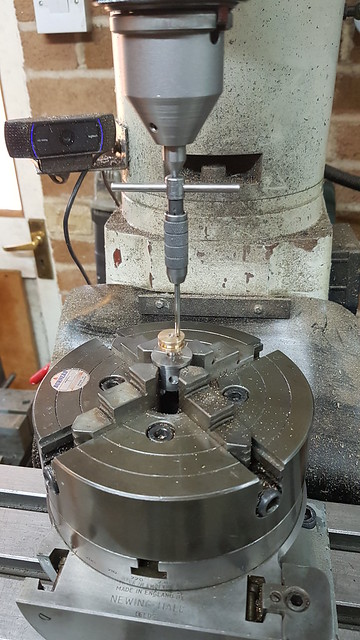 20190120_124959 20190120_124959 by Anne Froud, on Flickr The back side needs a clearance so water and steam can get past the 'O' ring and also let it flex a little. This was done after drilling the hole for the 'O' ring cord because it would be impossible to do it the other way round. 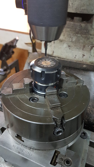 20190120_130811 20190120_130811 by Anne Froud, on Flickr The piston rod is Stainless Steel, so I decided to make the pivot pin from Phosphor Bronze. The arm is Mild Steel so it's a reasonable choice for that combination of materials. I know this will get wet, so maybe the arm should have been made from Stainless Steel too. Anyway, it's less likely to end up rusted solid with this as the pin. I'll have to grease the hole in the arm once it's painted. 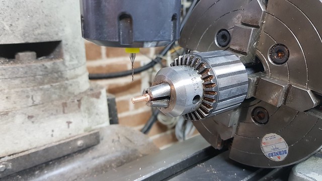 20190120_153653 20190120_153653 by Anne Froud, on Flickr So here are most of the parts of the Steam Brake arrangement. I'm probably going to have to fiddle with the 2mm ball valve to get it to seal, but that will have to wait until the next boat from China arrives with the Silicon Nitride balls. The pivot pin is retained by a Phosphor Bronze washer and a split pin. 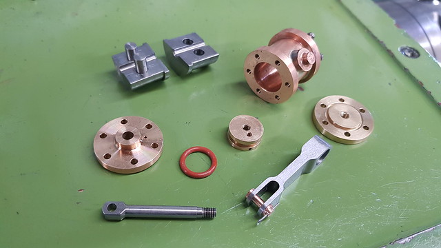 20190120_162739 20190120_162739 by Anne Froud, on Flickr |
|
|
|
Post by delaplume on Jan 20, 2019 18:59:51 GMT
Hi Roger,
Nice to see the M2.5 being "Floated" in there, matey !!.............I think your Avatar should now be the Mona Liza, as this latest job is surely a work of Art ??
I won't be at Ally Pally but look forwards to seeing you again up here in Shropshire this Spring /Summer ??.....Try and bring Julian this time ??
|
|