|
|
Post by Roger on Nov 15, 2019 9:00:51 GMT
Hi Roger, I'm not going to 'bite' at the suggestion a GWR, or GWR designed safety valve cover on a loco built under BR should have the front half polished, and the rear painted black! Never understood Whitworth spanners myself, but if the GWR had an ingrained use of them and BSW bolts, then I can go along with don9f's reasoning. I don't think those minuscule bolts and rivets are required on the safety valve cover to the check valve covers or the cleading, and have never noticed them myself on fullsize, but it is a nice detail that may only be applicable to 1501 as preserved on the SVR, and may be a result of its industrial usage and cannibalisation of 3 locos when they got to the SVR. Cheers, Julian Hi Julian, The half painted safety valve cover was just tongue in cheek of course. The drawing I'm working to is a general GWR one for eleven listed boiler types, so I think you'll find the rivets and bolts are on all of them. They're pretty small so they don't stand out. If you do a google image search of GWR locomotives and zoom in on that area, you'll see that they do indeed have the rivets at least. If you think about it, how else would they hold the shoulders onto the main body? I guess they could have countersunk them and polished over them, but that's a lot more work. Take a look at this picture, they're very clearly present on this locomotive. So I'd suggest that the reason you haven't noticed them is that they are inconspicuous rather than they are not there. |
|
|
|
Post by Roger on Nov 15, 2019 9:03:37 GMT
From my time working on GWR locos (full-size), I can't say I have found a non-standard plain bolt, they are nearly all BSW with standard hex sizes for the period. The only exception I can think of at the moment is the slide-bar bolts, they may be BSF. I do find it easy to get the correct spanner if you know the bolt size, easier than trying to remember the AF size for a particular bolt. Many fittings, and boiler stays, are 11 tpi, in particular with stays this allows you to go up a size, common practice on boilers, although some use 12 tpi. I think you will also find 11 tpi is standard size for larger pipe threads, although that is measured as the id of the pipe, where as most GWR fittings have the thread od, so not a common standard. Baldric. Hi Baldric, It's good to know what BSW is the assumed size used unless otherwise stated. The Whistle drawing I have mentions threads that are not consistent with the BSW spanner size that they're using on the outside of the casting. That's not altogether surprising, there's no need for them to be when it's a bespoke design. |
|
|
|
Post by 92220 on Nov 15, 2019 9:05:21 GMT
Hmm...well it makes no sense to me then...whereas I know that those in the mechanic trade will know a spanner size by the thread, ie a 6mm bolt has a 10 mm head, the way it's worded seems strange. It's Imperial, it doesn't have to make sense ;-) Thank goodness for Metric where common sense rules! Here's another drawing fragment which shows another hex. It was clearly obvious to the draughtsman what was meant, but it's a mystery to me.  Spanner required Spanner required by Timothy Froud, on Flickr Hi Roger. I've just drawn out that hex, in Autocad, scaled from the drawing. It scales out to 1.408" A/F, using the !.7/16" dimension as the reference dimension. However, a 7/8" Whit bolt is 1.3 to 1.288 A/F, so the hex is definitely a non standard size, and 1.480" A/F is for 1" Whit. Bob. |
|
|
|
Post by Roger on Nov 15, 2019 9:07:50 GMT
Some useful images of the mudhole doors and covers removed for possible boiler washout....Roger, do you know where and when these photos were taken ?? Hi Alan, The top one is one of mine from two years ago. The bottom one's file has a Modified property stamp of Nov 22nd 2015, but that doesn't guarantee it was taken then, only that it must be at least that old. |
|
|
|
Post by Roger on Nov 15, 2019 9:12:35 GMT
It's Imperial, it doesn't have to make sense ;-) Thank goodness for Metric where common sense rules! Here's another drawing fragment which shows another hex. It was clearly obvious to the draughtsman what was meant, but it's a mystery to me. Spanner required by Timothy Froud, on Flickr Hi Roger. I've just drawn out that hex, in Autocad, scaled from the drawing. It scales out to 1.408" A/F, using the !.7/16" dimension as the reference dimension. However, a 7/8" Whit bolt is 1.3 to 1.288 A/F, so the hex is definitely a non standard size, and 1.480" A/F is for 1" Whit. Bob. Hi Bob, I'm not sure you can deduce the AF size from the outer radii, the drawings were done by hand and I'd be very surprised of the radii were that accurate. I'm more inclined to figure out the intended spanner size and make the blends to suit. You don't have enough detail on the drawing to guarantee how the small radius at the bottom meets the hex to draw any firm conclusions from the geometry based on that in my opinion. |
|
|
|
Post by Roger on Nov 15, 2019 9:14:52 GMT
One other point to make is that the Railway Companies and BR that followed, often specified their own threads / diameters / spanner sizes that didn’t conform to any commercially available size. For example lots of steam fittings used 11tpi Whitworth form threads and whatever diameter and spanner sizes suited the job. BR did make some use of British Standard Pipe sizes, for instance in the myriad selection of nuts, cones and unions for all the different pipe diameters. Cheers Don One could go further than this. The GWR manufactured everything it could in-house. Sometimes they deliberately chose non-standard sizes for some items to make them less attractive to thieves. (They were a little obsessed with thieving which is why GWR branding was applied to virtually everything.) They made their own bricks, believe it or not, and to a special GWR size for this reason, or so I was told at Didcot. Not saying this was the case with nuts and bolts, but it isn't impossible! They made their own taps and dies and nuts and bolts at Swindon and were prohibited by law from selling them to anyone else, so they had no good reason to adhere to wider industry standards, and a certain incentive not to. I don't think this helps with your thread enquiry Roger! I think scaling from the drawing is the best advice, if you can't measure the item itself. Best regards Gary Thanks for that Gary. I've also done a google image search for GWR Whistles and there are quite a few on auction sites with really nice close up pictures. That really helps to check whether the proportions are right. |
|
|
|
Post by 92220 on Nov 15, 2019 10:10:19 GMT
Hi Roger.
I know scaling off hand drawn drawings can be dodgy, however, After scaling the drawing to get the 1.7/16" dimension to scale, I also checked the vertical 3/4" dimensions, and they were very close to scale too, at 0.740", so I am pretty sure I've got it close. I was a design draughtsman in the dim and distant past, drawing equipment that was being supplied to the Admiralty, for warships, and we did all our drawings on Melinex draughting film and, using 3H pencils, sharpened to a sharp point, or Rotring indian ink pens, (I've still got my set and the smallest produces a 0.1mm line) we always tried to end up with accurate scale drawings, so that they could be measured off, by engineering ratings on board ship. All the railway drawings I have ever had to scale, have all been pretty close to accurate size too. I think it was a 'pride' thing, that draughtsmen always tried to end up with as near true to scale drawings as possible. Also, drawings in larger companies were always checked by checkers and because they were considered inferior to draughtsmen, they used to take great delight in throwing a drawing back to the draughtsman because it 'wasn't right'!!
Bob.
|
|
|
|
Post by Deleted on Nov 15, 2019 10:21:02 GMT
Hi Bob
I would have thought that most drawings began life to scale, I don't see how anyone doing the drawing could draw it otherwise? The issue that messes things up is when said drawing is reproduced/printed. This can affect the scale, either too small or too large. When I scale from drawings I measure something that's drawn and has a dimension stated in both axis and if there is a discrepancy I calculate the ratio and multiply/subtract by that amount accordingly.
Pete
|
|
|
|
Post by delaplume on Nov 15, 2019 11:11:20 GMT
Hi Bob I would have thought that most drawings began life to scale, I don't see how anyone doing the drawing could draw it otherwise? The issue that messes things up is when said drawing is reproduced/printed. This can affect the scale, either too small or too large. When I scale from drawings I measure something that's drawn and has a dimension stated in both axis and if there is a discrepancy I calculate the ratio and multiply/subtract by that amount accordingly. Pete Hello all, As you can imagine when I was researching the Great Bear archives from GWR drawings at ( and copies supplied from----) York Museum I came across the same problem............I ended up applying a similar technique}--- I'd choose a well known dimention --- let's say the Driving wheel pitch at 7 feet -- and transfer the actual physical size from that drawing onto a piece of blank paper..Divide this line into 7 and thus each of those units now represents 1 foot back on the main drawing, but ONLY ON THAT DRAWING !!...... This process is not transferrable mainly due to different paper stretch rates when printing or photocopying...etc. Further sub-division into 12 would give an inch ( if physically possible )......... Now select another well documented size and "Reverse Engineer" to cross-check your answers......... And from a total of 10 original sheets I was able to re-create enough drawings dimentioned at 1.0625 ins. per foot for 5 ins. gauge production.. |
|
|
|
Post by delaplume on Nov 15, 2019 11:32:44 GMT
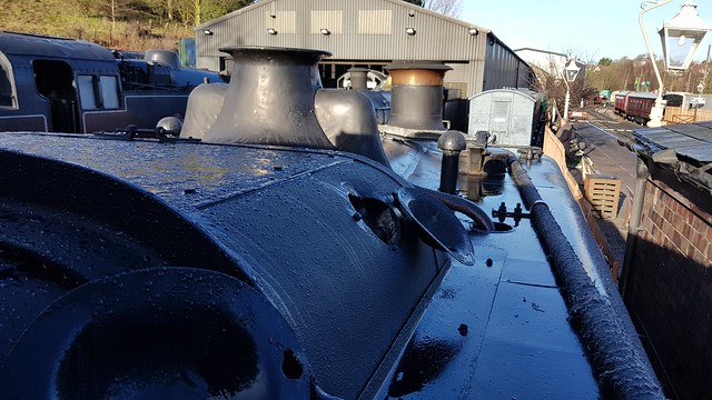
Hi Roger........ Referring to those 2 photos recently}---
Oh, that's a pity....I was hoping that the top photo was from just after 1501 arrived at B'North from NCB ownership and thus the whole of the bonnet was black.... Not so it would seem...
Have you tried writing to the current owners and asking for some livery history whilst at the SVR ??
Referring to that original GWR / BR drawing of yours ---- my initial feeling was that "7/8" spanner referred to a Whitworth form applied on a bolt of that diameter....
Those on here who have worked in Heritage Steam MPDs' will know just what an accumulation of tools that can be found in the so-called "Spanner Racks".....made all the more frustrating with the addition of donated tools down the years..... many of which are either unmarked, worn, or non-preferred within the system eg Metric, Unified etc.....
11 TPI ??....As a volunteer, then as a Self Employed contractor that gave many a headache initially.........Once tooled-up with the appropiate Taps, Dies etc and a lathe set up it wasn't so bad....
Eventually I specialised in producing the snap-valves, but that's for another thread....
|
|
|
|
Post by Roger on Nov 15, 2019 12:06:57 GMT
Hi Roger. I know scaling off hand drawn drawings can be dodgy, however, After scaling the drawing to get the 1.7/16" dimension to scale, I also checked the vertical 3/4" dimensions, and they were very close to scale too, at 0.740", so I am pretty sure I've got it close. I was a design draughtsman in the dim and distant past, drawing equipment that was being supplied to the Admiralty, for warships, and we did all our drawings on Melinex draughting film and, using 3H pencils, sharpened to a sharp point, or Rotring indian ink pens, (I've still got my set and the smallest produces a 0.1mm line) we always tried to end up with accurate scale drawings, so that they could be measured off, by engineering ratings on board ship. All the railway drawings I have ever had to scale, have all been pretty close to accurate size too. I think it was a 'pride' thing, that draughtsmen always tried to end up with as near true to scale drawings as possible. Also, drawings in larger companies were always checked by checkers and because they were considered inferior to draughtsmen, they used to take great delight in throwing a drawing back to the draughtsman because it 'wasn't right'!! Bob. Hi Bob, This is all true to some degree, but there are some pretty big assumptions in there. The radii are assumed to blend perfectly and that the big one starts at an exact tangent to the outside. then there's the biggest problem which is how that final blend to the hex ends up. If it points to being very close to the Whitworth spanner implied by the drawing size then that's confirmation that these are fair assumptions. If not, I'd be very wary of believing the calculated values from the assumptions. The Works Drawings for the Combined Steam and Vacuum brake casting are a case in point where the notional radii simply don't fit when you try to draw it. Anything without a specifically dimensioned arc centre is suspect in my opinion. |
|
|
|
Post by Roger on Nov 15, 2019 12:10:07 GMT
Hi Bob I would have thought that most drawings began life to scale, I don't see how anyone doing the drawing could draw it otherwise? The issue that messes things up is when said drawing is reproduced/printed. This can affect the scale, either too small or too large. When I scale from drawings I measure something that's drawn and has a dimension stated in both axis and if there is a discrepancy I calculate the ratio and multiply/subtract by that amount accordingly. Pete Hi Pete, This is true, but with hanging dimensions that don't specify and arc centre, or a blend that's not clearly defined such as in the bottom where it meets the hex could be that the nominal radius given is more of a guide than to be taken as gospel truth. I wouldn't scale anything from a drawing unless it was a last resort with nothing else to go on. As long as the approximated scaled value indicates it's close to the size suggested by the spanner then I don't think you can trust the radii. |
|
|
|
Post by Deleted on Nov 15, 2019 12:34:52 GMT
Ah, but Roger you are living in the modern world of CNC where such things are critical. I'm very much in the hand and eye world where everything is done by eye...I don't need a fixed point for an arc....  Pete |
|
|
|
Post by Jim on Nov 15, 2019 20:33:47 GMT
|
|
|
|
Post by Roger on Nov 15, 2019 22:05:57 GMT
Ah, but Roger you are living in the modern world of CNC where such things are critical. I'm very much in the hand and eye world where everything is done by eye...I don't need a fixed point for an arc.... Pete Well, it doesn't really matter whether it's micron perfect, but if there's a dimension you might as well use it. I'm pretty sure the drawings are using the old pre-war BSW AF spanner sizes to BS190, not the later one suggested by Baldric. That makes sense when you look at the date on the drawing which is June 1930. Although that was about the time the new smaller AF standard was formalised, it seems highly unlikely that Swindon would have been adopting it, I doubt if they even knew it existed! Anyway, I think the puzzle has been solved and the only thing to do is to massage some of the blending details where the curves meet the Hex to get something that looks right. Using the precise dimensions and the small blend at the bottom results in a very weird 'chamfer' that's clearly not what's on the finished article. |
|
|
|
Post by steamer5 on Nov 15, 2019 23:05:45 GMT
Hi Roger,
Maybe a bit of an off side but a couple of weeks ago I was in the same boat, except the part had NO DIMENSIONS!
A call to my son via Viber in Canada for some questioning on what to do. Easy, well for him any way, import the drawing, mine a re PDF, straight into CAD, you then find yourself a nice clear dimension, select the whole of the drawing this bit is important top right to bottom left, he did explain why but I’m not sure now, you then type SC, for scale & follow the instruction. Done! Then just draw a line or arc ( use the 3 point option) check the properties & see how close you are. If not the tweak the scale on the drawing properties. Worked great for me, the drawings are 1908 & when you zoom in they tend to get a bit fuzzy, so a little fluffy it about on start end of the line can help. You probably know all this but just incase.
Now for the really weird bit, as I was doing this via Viber & can do video at the same time I had my phone viewing the screen so he could watch & talk me thru it. With the drawing zoomed I happen to notice that the picture on the phone was nice & clear! No fuzzy lines. I have since tried with the magnifying app & it’s no we’re near as clear. Hope some of this rambling is of use.
Cheers Kerrin
|
|
|
|
Post by Roger on Nov 15, 2019 23:20:52 GMT
Hi Roger, Maybe a bit of an off side but a couple of weeks ago I was in the same boat, except the part had NO DIMENSIONS! A call to my son via Viber in Canada for some questioning on what to do. Easy, well for him any way, import the drawing, mine a re PDF, straight into CAD, you then find yourself a nice clear dimension, select the whole of the drawing this bit is important top right to bottom left, he did explain why but I’m not sure now, you then type SC, for scale & follow the instruction. Done! Then just draw a line or arc ( use the 3 point option) check the properties & see how close you are. If not the tweak the scale on the drawing properties. Worked great for me, the drawings are 1908 & when you zoom in they tend to get a bit fuzzy, so a little fluffy it about on start end of the line can help. You probably know all this but just incase. Now for the really weird bit, as I was doing this via Viber & can do video at the same time I had my phone viewing the screen so he could watch & talk me thru it. With the drawing zoomed I happen to notice that the picture on the phone was nice & clear! No fuzzy lines. I have since tried with the magnifying app & it’s no we’re near as clear. Hope some of this rambling is of use. Cheers Kerrin Hi Kerrin, I've heard of others doing similar things, but not from Works Drawings. What CAD system are you using for that? I've scaled drawings manually using the same method, but long hand to get the scale factor. I don't like doing it, but sometimes there's no option and it's all I've got. These phone apps are amazing. I use WhatsApp for text messaging and sending pictures these days, but I've not used Viber although it's on my phone. All interesting stuff. |
|
|
|
Post by steamer5 on Nov 15, 2019 23:46:29 GMT
Hi Roger,
Currently using Draftsite.....soon to be Fusion 360. My son is using auto cad......not sure which but he does most of his work in 3D. Given that I was following his instruction the key commands are the same.
It’s definitely a great way to check dimensions, they may not be spot on but it gets you pretty close to the ball park, after all when you look at the drawings most bits are ( well at least on the Garratt drawings) to 1/8”, it’s not until you get to critical stuff that it gets closer.....& lucky for me the drawings for these are clearer!
Cheers Kerrin
|
|
dscott
Elder Statesman

Posts: 2,438
|
Post by dscott on Nov 16, 2019 0:14:48 GMT
Now it makes perfect sense why Roger is using all metric sizes and threads as when he is finished there is no point in Borrowing a part for our own projects as they will not fit!!
Joking!!!
Yes even the smallest fist sized road cover for Gas or Water had GWR cast in so No Nicking. I have a Gas one found in a skip by a station in my misspent youth.
OOPS and a Brass bolt also stamped from inside a tank at Buckfastleigh. Look I was the only one thin enough to fit inside to do up the bolts (Possibly Metric) Naming the tanks Bulliver and ? It was a long time ago and they run far better without them!!!
David just finished a jam sandwich to keep pants up.
|
|
peteh
Statesman
 Still making mistakes!
Posts: 760
|
Post by peteh on Nov 16, 2019 7:32:54 GMT
The problem with the single distance used to scale a drawing is that a paper drawing is often stretched along its length by a different factor than its width, often caused by the copy method. If this is the case make the image a block and then insert with independant x and y scales to correct in both directions and then explode it to bring it back to a simple image. Used this many times to correct plans for town planning when I was in that field.
|
|