|
|
Post by ettingtonliam on Nov 12, 2019 18:17:50 GMT
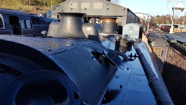
Well I thought the first bonnet looked pretty good, but I have to admit this second one is even better!
If the clack covers have that little flange under the bonnet, how does the whole thing sit down on the cladding without gaps showing? Presumably Swindon 'dressed' it to fit, i.e. hit it with a hammer?
|
|
|
|
Post by Roger on Nov 12, 2019 22:03:33 GMT
Well I thought the first bonnet looked pretty good, but I have to admit this second one is even better! If the clack covers have that little flange under the bonnet, how does the whole thing sit down on the cladding without gaps showing? Presumably Swindon 'dressed' it to fit, i.e. hit it with a hammer? I'm glad you like it, it's been worth the effort. Yes, I think you've got the measure of how it was done. It doesn't fit that closely, in fact it's a bit of a mess really, but it's good enough. There are six bolts holding it as closely as possible to the cladding, the thickness of the flange isn't that great so it doesn't look too bad. Mine will be just the same, the flange is really thin where it shows. So here's the fixture in action on the tilting rotary table. I could get close enough on the first hole with the ER32 collet chuck...  20191112_202857 20191112_202857 by Timothy Froud, on Flickr ... but not on the others. 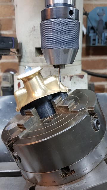 20191112_205219 20191112_205219 by Timothy Froud, on Flickr This is a 0.5mm PCB drill, so there's no need for a centre drill.  20191112_205622 20191112_205622 by Timothy Froud, on Flickr I've set these up by eye, it's not really feasible to put them in perfectly without going to a huge amount of effort. The position of the middle rivet holes isn't dimensioned on the Works Drawing. The notional position is way lower than it was done on 1501, so I guess they didn't really care exactly where they went as long as there was one supporting the middle.  20191112_211724 20191112_211724 by Timothy Froud, on Flickr I've still got the six 0.8mm bolt holes to go in around the flange, but I'm out of time tonight. |
|
|
|
Post by Roger on Nov 14, 2019 19:09:35 GMT
Could someone tell me what they mean on GWR Works Drawings when they say that a hex is to suit a 1/2" spanner? Is that Whitworth, BSF or some other Imperial standard? My guess is that it's Whitworth else the size looks too small. I've attached the dummy clack valve tops to the shoulders with Loctite 620 High Strength, High temperature retainer. The 0.5mm diameter Brass rivets arrived today. I think it's those, but it's more like Brass hairs!  20191114_113510 20191114_113510 by Timothy Froud, on Flickr |
|
|
|
Post by Deleted on Nov 14, 2019 19:18:50 GMT
Hi Roger
I know nothing of GWR drawings but to me they mean the hex is 1/2" across flats, so, without using a caculator that would be just over 1mm AF.
Pete
|
|
|
|
Post by Roger on Nov 14, 2019 19:44:28 GMT
Hi Roger I know nothing of GWR drawings but to me they mean the hex is 1/2" across flats, so, without using a caculator that would be just over 1mm AF. Pete Hi Pete, That's not possible when you look at the other dimensions. It must refer to the thread size. I found a couple of charts here and here on the internet that show the possibilities. |
|
|
|
Post by Roger on Nov 14, 2019 19:49:03 GMT
|
|
|
|
Post by Deleted on Nov 14, 2019 19:56:07 GMT
Hi Roger I know nothing of GWR drawings but to me they mean the hex is 1/2" across flats, so, without using a caculator that would be just over 1mm AF. Pete Hi Pete, That's not possible when you look at the other dimensions. It must refer to the thread size. I found a couple of charts here and here on the internet that show the possibilities. Hmm...well it makes no sense to me then...whereas I know that those in the mechanic trade will know a spanner size by the thread, ie a 6mm bolt has a 10 mm head, the way it's worded seems strange. |
|
don9f
Statesman
 Les Warnett 9F, Martin Evans “Jinty”, a part built “Austin 7” and now a part built Springbok B1.
Posts: 960 
|
Post by don9f on Nov 14, 2019 20:00:11 GMT
As you probably know, Whitworth hex sizes were reduced at some point in the early part of the 20th century to one size less. During WW2 this practice became more widely adopted (to save metal?).....so depending on the age of any drawings you refer to, 1/2” could be one size or another !!!
Nowadays 1/2” is not a preferred Whitworth spanner size and for a 1/2” BSW bolt/nut, 7/16” is the one.
Very confusing but the charts you linked to are very helpful.
Cheers Don (still use Whitworth a lot)
|
|
|
|
Post by simplyloco on Nov 14, 2019 20:17:56 GMT
Roger, I know that you've got all this knowledge and some clever machines, but why didn't you take the easy route and make the bonnet using a balsa wood dummy and some Milliput epoxy putty?  Works for me...most of the time! John |
|
|
|
Post by Roger on Nov 14, 2019 20:35:02 GMT
Hi Pete, That's not possible when you look at the other dimensions. It must refer to the thread size. I found a couple of charts here and here on the internet that show the possibilities. Hmm...well it makes no sense to me then...whereas I know that those in the mechanic trade will know a spanner size by the thread, ie a 6mm bolt has a 10 mm head, the way it's worded seems strange. It's Imperial, it doesn't have to make sense ;-) Thank goodness for Metric where common sense rules! Here's another drawing fragment which shows another hex. It was clearly obvious to the draughtsman what was meant, but it's a mystery to me.  Spanner required Spanner required by Timothy Froud, on Flickr |
|
don9f
Statesman
Les Warnett 9F, Martin Evans “Jinty”, a part built “Austin 7” and now a part built Springbok B1.
Posts: 960
|
Post by don9f on Nov 14, 2019 20:55:55 GMT
For that previous drawing referring to a “7/8” spanner I would say the A/F would be 1.480”, as per the 7/8” Whitworth size in the second chart you linked to. Note the dimension of 1 7/16” dia. just above the hexagon area.
Does that help?
Cheers Don
|
|
|
|
Post by Deleted on Nov 14, 2019 20:58:32 GMT
I can now see that Whitworth and BSF don't measure A/F...fair enough. If the drawing saying 'for 1/2" spanner' is as clear as the 7/8 spanner drawing I'd just scale off the drawing. You should be able to work out the exact head size.
Pete
|
|
|
|
Post by Roger on Nov 14, 2019 21:19:47 GMT
For that previous drawing referring to a “7/8” spanner I would say the A/F would be 1.480”, as per the 7/8” Whitworth size in the second chart you linked to. Note the dimension of 1 7/16” dia. just above the hexagon area. Does that help? Cheers Don I think that's what it is, when scaled to that is does look about right. At least that part of the drawing can be read, some of it I'm guessing because it's too blurred to be certain what it says. |
|
baldric
E-xcellent poster

Posts: 208
|
Post by baldric on Nov 14, 2019 21:28:00 GMT
en.m.wikipedia.org/wiki/British_Standard_WhitworthThe section "comparison with other standards" has a good table for the hex sizes. As the 15xx are post WW2 I would use BS1083. These sizes show why you can get some odd size hex bar. Many fittings have the hex parts marks as to fit xxx spanner. Baldric.
|
|
|
|
Post by Roger on Nov 14, 2019 21:34:47 GMT
en.m.wikipedia.org/wiki/British_Standard_WhitworthThe section "comparison with other standards" has a good table for the hex sizes. As the 15xx are post WW2 I would use BS1083. These sizes show why you can get some odd size hex bar. Many fittings have the hex parts marks as to fit xxx spanner. Baldric. Thanks Baldric, I've bookmarked that. |
|
jma1009
Elder Statesman

Posts: 5,901
|
Post by jma1009 on Nov 14, 2019 23:33:34 GMT
Hi Roger,
I'm not going to 'bite' at the suggestion a GWR, or GWR designed safety valve cover on a loco built under BR should have the front half polished, and the rear painted black!
Never understood Whitworth spanners myself, but if the GWR had an ingrained use of them and BSW bolts, then I can go along with don9f's reasoning.
I don't think those minuscule bolts and rivets are required on the safety valve cover to the check valve covers or the cleading, and have never noticed them myself on fullsize, but it is a nice detail that may only be applicable to 1501 as preserved on the SVR, and may be a result of its industrial usage and cannibalisation of 3 locos when they got to the SVR.
Cheers,
Julian
|
|
don9f
Statesman
Les Warnett 9F, Martin Evans “Jinty”, a part built “Austin 7” and now a part built Springbok B1.
Posts: 960
|
Post by don9f on Nov 14, 2019 23:39:11 GMT
One other point to make is that the Railway Companies and BR that followed, often specified their own threads / diameters / spanner sizes that didn’t conform to any commercially available size.
For example lots of steam fittings used 11tpi Whitworth form threads and whatever diameter and spanner sizes suited the job. BR did make some use of British Standard Pipe sizes, for instance in the myriad selection of nuts, cones and unions for all the different pipe diameters.
Cheers Don
|
|
|
|
Post by delaplume on Nov 15, 2019 0:20:11 GMT
Some useful images of the mudhole doors and covers removed for possible boiler washout....Roger, do you know where and when these photos were taken ?? |
|
Gary L
Elder Statesman
Posts: 1,208
|
Post by Gary L on Nov 15, 2019 0:28:42 GMT
One other point to make is that the Railway Companies and BR that followed, often specified their own threads / diameters / spanner sizes that didn’t conform to any commercially available size. For example lots of steam fittings used 11tpi Whitworth form threads and whatever diameter and spanner sizes suited the job. BR did make some use of British Standard Pipe sizes, for instance in the myriad selection of nuts, cones and unions for all the different pipe diameters. Cheers Don One could go further than this. The GWR manufactured everything it could in-house. Sometimes they deliberately chose non-standard sizes for some items to make them less attractive to thieves. (They were a little obsessed with thieving which is why GWR branding was applied to virtually everything.) They made their own bricks, believe it or not, and to a special GWR size for this reason, or so I was told at Didcot. Not saying this was the case with nuts and bolts, but it isn't impossible! They made their own taps and dies and nuts and bolts at Swindon and were prohibited by law from selling them to anyone else, so they had no good reason to adhere to wider industry standards, and a certain incentive not to. I don't think this helps with your thread enquiry Roger! I think scaling from the drawing is the best advice, if you can't measure the item itself. Best regards Gary |
|
baldric
E-xcellent poster
Posts: 208
|
Post by baldric on Nov 15, 2019 6:05:00 GMT
From my time working on GWR locos (full-size), I can't say I have found a non-standard plain bolt, they are nearly all BSW with standard hex sizes for the period. The only exception I can think of at the moment is the slide-bar bolts, they may be BSF. I do find it easy to get the correct spanner if you know the bolt size, easier than trying to remember the AF size for a particular bolt.
Many fittings, and boiler stays, are 11 tpi, in particular with stays this allows you to go up a size, common practice on boilers, although some use 12 tpi. I think you will also find 11 tpi is standard size for larger pipe threads, although that is measured as the id of the pipe, where as most GWR fittings have the thread od, so not a common standard.
Baldric.
|
|