barlowworks
Statesman
 Now finished my other projects, Britannia here I come
Posts: 874 
|
Post by barlowworks on Mar 21, 2020 22:36:05 GMT
I must admit I've never seen a shoe there before, I always thought they were on the front bogie, you live and learn Mike The BR system introduced in the 1950s is on the front bogie. What was posted was the earlier GWR system (1930s I think). Apologies to Roger for hijacking his thread but I've got to ask, Would a early W.R. Britannia (about 1955) have the shoe on the bogie or under the cab.
Mike
|
|
don9f
Statesman
Les Warnett 9F, Martin Evans “Jinty”, a part built “Austin 7” and now a part built Springbok B1.
Posts: 960
|
Post by don9f on Mar 21, 2020 23:42:12 GMT
Yes, apologies to Roger but just this one post from me....see this photo of “Shooting Star”, when a WR engine. Notice the electrical conduit running under the lower edge of the running board, from the battery box under the cab, until it disappears in front of the LH cylinder valvechest. This would carry the wiring to the ATC “shoe”, which is obviously at the front of the engine somewhere....but I don’t know exactly where!  It looks like it would have been on the bogie, but just to muddy the water, 9Fs carried it on a bracket, supported under the leading driving axle, but of course they had a pony truck, which may not have been suitable. Interesting conundrum, maybe someone has drawing info? Cheers Don |
|
|
|
Post by 92220 on Mar 22, 2020 13:06:56 GMT
I have just found a B.R. drawing that shows the Britannias with the shoe mounted below the front bogie axle. I also have another B.R. drawing that shows the ATC shoe mounted below the front coupled axle, on a Class 3 2-6-2, as do the 9Fs.
Bob.
|
|
baldric
E-xcellent poster

Posts: 208
Member is Online
|
Post by baldric on Mar 22, 2020 13:48:52 GMT
On the GWR there were 2 types of shoe, the vertical one as seen earlier fitted to the back of a Castle, these are sometimes fitted to the front of some engines like the one on 7202  DSCN0228 (2) DSCN0228 (2) by Mark Baldry, on Flickr The other type has more of a rocking arm, this can be seen on the pony-truck of 3822  DCP00452 DCP00452 by Mark Baldry, on Flickr It is attached to 2 beams that are between the axleboxes, this is how they are fitted to the leading axleboxes on the 57xx class engines, at least on the 3600 series, I assume it is this type that would have been fitted to the BR standards as well. I am not sure which type would have been fitted to the 15xx. Baldric |
|
|
|
Post by ettingtonliam on Mar 22, 2020 17:26:15 GMT
I have a vague memory of reading somewhere that the shoe was originally at the rear but was moved because 'bounce' at the rear end made the system unreliable at speed.
|
|
Andrew C
Part of the e-furniture
Posts: 447
|
Post by Andrew C on Mar 22, 2020 17:38:32 GMT
|
|
|
|
Post by Roger on Mar 22, 2020 18:24:03 GMT
Hi Andrew, Thanks, that was the one I found and mentioned before, but I couldn't see a way to link. I've got it downloaded though. 1501 has the ATC box shown in that document, but I also have a copy of ME8086 which is a pdf of the general arrangement. That doesn't have any dimensions though, but it does appear to be to scale. |
|
Gary L
Elder Statesman

Posts: 1,208
|
Post by Gary L on Mar 23, 2020 1:41:43 GMT
I have a vague memory of reading somewhere that the shoe was originally at the rear but was moved because 'bounce' at the rear end made the system unreliable at speed. The GA drawing shows the shoe fitted between two cross-beams beneath the front axle. A detail too far for me! Especially since ATC is not used in preservation AFAIK HTH Gary |
|
|
|
Post by delaplume on Mar 23, 2020 13:20:15 GMT
Hello all, What a great view of a typical Churchward Bar-Frame type of Pony truck as seen from within the inspection pit.......Notice the long neck of the axlebox oil fillers and the taper cork bungs at the top ( The L/H one appears damaged ).... .After leaving the RN I was a Diesel Fitter at 81D Reading ( Cow Lane ) MPD for a few years and recognise that lever type mounting for the cast iron slider shoe...As mentioned elsewhere it was used on the first generation DMU's and had to be changed if deeply grooved........The unofficial rule was to change them at each scheduled inspection regardless ..All work being Time and Motion rated .. Have just found this}----- www.railsigns.uk/sect12page1/sect12page1.htmlSorry Roger, I'll "toe the Party Line" from now on --LoL. |
|
|
|
Post by Roger on Mar 24, 2020 11:23:55 GMT
Next up on the sliding screens are the rails and supporting pieces. On the full sized locomotive these are threaded and the outside has a nut on them. However, these are so small that I don't think that's going to be practical. The plan is to rivet these over and attach them permanently before painting. In any case, the outside would have to be painted over, even if it used a nut. So the first operation is to machine the securing pin and the end profile...  20200323_212729 20200323_212729 by The train Man, on Flickr ... followed by the hole for the rod. I've used the tilting rotary table so that it's held at the right angle without having to take it out of the chuck.  20200323_214300 20200323_214300 by The train Man, on Flickr I've made a couple of filing buttons from Silver Steel so I can finish the end radius...  20200324_090013 20200324_090013 by The train Man, on Flickr ... like this.  20200324_092812 20200324_092812 by The train Man, on Flickr A pin chuck comes in handy for holding this while filing and finishing with Emery paper. 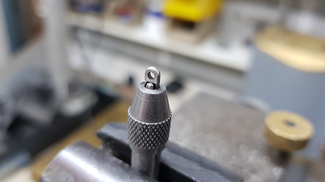 20200324_094721 20200324_094721 by The train Man, on Flickr  20200324_102925 20200324_102925 by The train Man, on Flickr They're pretty small.  20200324_103008 20200324_103008 by The train Man, on Flickr |
|
|
|
Post by Doug on Mar 24, 2020 16:11:04 GMT
Is it me or are all your parts getting smaller and smaller...... or are your hands getting bigger?
Nice work
|
|
|
|
Post by Roger on Mar 24, 2020 21:09:26 GMT
I want to rivet the location pin of the bracket over, but there's no way to support the bracket without damaging it. This is a piece of Silver Steel that will support a rod going through the eye of the bracket. The idea is to press against the bottom of the eye so it doesn't deform the hole when riveting the end over. I can easily create a 1.6mm diameter Semi-Circle on the end by drilling a hole...  20200324_151443 20200324_151443 by The train Man, on Flickr ... then machining half of it away. Then a clearance was machined to clear the width of the bracket...  20200324_154244 20200324_154244 by The train Man, on Flickr ... so it goes in this position. 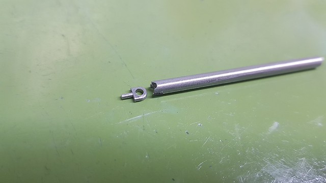 20200324_155958 20200324_155958 by The train Man, on Flickr The eye brackets are located with a piece of Silver Steel which is being held in place with Blue-tac.  20200324_164003 20200324_164003 by The train Man, on Flickr The support can be used as an anvil in the rivet press, or in the vice.  20200324_164059 20200324_164059 by The train Man, on Flickr It all ends up like this, the bottom joggled bracket resting in position on a couple of rivets. 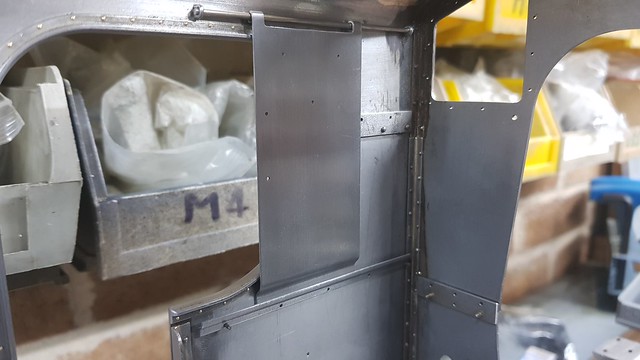 20200324_205248 20200324_205248 by The train Man, on Flickr I think I must have picked up a piece of EN8 which I used to make two of the eye brackets. As a result, I couldn't form a head on those, so I decided to flush rivet them.  20200324_205825 20200324_205825 by The train Man, on Flickr |
|
|
|
Post by Roger on Mar 27, 2020 21:27:10 GMT
The tops of the Axle driven feed pump and the mechanical lubricator eccentrics are inaccessible for oiling because the Pannier Tanks get in the way. I've got a decent sized rectangular reservoir in the top of the eccentric straps, but no way to get oil into them at present. I've decided to make an oblong oiler extension that attaches to the eccentric strap so that a fixed oiling point can feed into it in any wheel position. The extension piece is going to be a push fit in the rectangular pocket in the strap, and this will be the inside of the location piece, machined using a 2mm 4-flute Carbide End Mill. 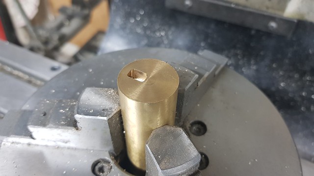 20200326_202115 20200326_202115 by The train Man, on Flickr It ends up like this when the outside is machined. I've done it this way so I can test fit the strap to it and trim the outside of the location with fine finishing passes until the fit is right.  20200326_213825 20200326_213825 by The train Man, on Flickr  20200326_213845 20200326_213845 by The train Man, on Flickr  20200327_210052 20200327_210052 by The train Man, on Flickr I've added a little Loctite 574 flange sealant so it won't leak. The intention is to squirt a measured amount through a feed tube and use the trough as a reservoir. The oil is pretty thick so I think it will stay put. I don't want to mess about with wicks and tiny tubes.  20200327_211153 20200327_211153 by The train Man, on Flickr  20200327_215442 20200327_215442 by The train Man, on Flickr |
|
|
|
Post by andyhigham on Mar 27, 2020 22:09:23 GMT
Will you fit a lid to stop the oil getting flung out?
|
|
|
|
Post by Roger on Mar 27, 2020 22:41:44 GMT
Will you fit a lid to stop the oil getting flung out? I don't think it will be necessary with the heavy oil I'm using. |
|
Gary L
Elder Statesman
Posts: 1,208
|
Post by Gary L on Mar 27, 2020 23:21:31 GMT
Will you fit a lid to stop the oil getting flung out? I don't think it will be necessary with the heavy oil I'm using. My Speedy had lidded oil boxes fixed to each frame, with pipes going to each axle box and a single extra pipe to the eccentric. Not prototypical, but then neither is the eccentric. Without it (or something similar), oiling the horns/axle boxes and the eccentric would be a nightmare, because as you say Roger, the pannier tanks hide everything from view and you are working blind. Thick oil is fine once everything warms up (and I cut mine 50/50 with chainsaw oil which helps) It's not unique to Pannier Tanks, side tanks can be equally bad if not worse, but there has to be some way of doing it, preferably without putting the loco over a pit. Gary |
|
|
|
Post by delaplume on Mar 27, 2020 23:58:18 GMT
Hi Roger,
Personally I would fit a hinged lid..........not to keep the oil in, but to keep particles of grit out...I've not done it myself but have seen a piece of coarse sponge fitted into that reservoir you've just created...It retains the oil and prevents ingress of the grit etc.
It might be a bit late in the day now but you could create a "reservoir" by machining a semi-circular groove into the eccentric's surface and then fill with steam oil when assembling the 2 strap halves....That would last all season I would have thought..
Axleboxes can be lubricated via a small hole into the end of the axle connecting to a cross-drilling equal to approx. half the depth of the box...
|
|
|
|
Post by Roger on Mar 28, 2020 7:48:22 GMT
Hi Roger, Personally I would fit a hinged lid..........not to keep the oil in, but to keep particles of grit out...I've not done it myself but have seen a piece of coarse sponge fitted into that reservoir you've just created...It retains the oil and prevents ingress of the grit etc. It might be a bit late in the day now but you could create a "reservoir" by machining a semi-circular groove into the eccentric's surface and then fill with steam oil when assembling the 2 strap halves....That would last all season I would have thought.. Axleboxes can be lubricated via a small hole into the end of the axle connecting to a cross-drilling equal to approx. half the depth of the box... Hi Alan, Unfortunately you can't have a lid because oil needs to be able to get into the reservoir in whatever position the driving wheels are in. I'll just cut a piece of mesh to sit in the bottom of the trough to keep the muck out. There is an internal cavity in the eccentric which can be filled from a small hole in the side of the eccentric, but I didn't think that would be enough on its own. It's a bit fiddly to get to, but you can see it through the gap in the spokes of the wheel and the above the axlebox. I think that's one for oiling on the bench before heading out. Oiling the axleboxes is easy because I can get a small tube in the gap between the top of the axleboxes and the horns. There's a large cavity in the top of the axleboxes. Those do have covers and a small hole in the top for oiling. Although I like the idea of oiling from cross drilled holes in the axles, there isn't much volume being stored there. I wanted to make sure there was a decent supply of oil coming from the reservoir. |
|
Gary L
Elder Statesman
Posts: 1,208
|
Post by Gary L on Mar 28, 2020 11:02:28 GMT
Hi Roger, Personally I would fit a hinged lid..........not to keep the oil in, but to keep particles of grit out...I've not done it myself but have seen a piece of coarse sponge fitted into that reservoir you've just created...It retains the oil and prevents ingress of the grit etc. It might be a bit late in the day now but you could create a "reservoir" by machining a semi-circular groove into the eccentric's surface and then fill with steam oil when assembling the 2 strap halves....That would last all season I would have thought.. Axleboxes can be lubricated via a small hole into the end of the axle connecting to a cross-drilling equal to approx. half the depth of the box... Hi Alan, Unfortunately you can't have a lid because oil needs to be able to get into the reservoir in whatever position the driving wheels are in. I'll just cut a piece of mesh to sit in the bottom of the trough to keep the muck out. There is an internal cavity in the eccentric which can be filled from a small hole in the side of the eccentric, but I didn't think that would be enough on its own. It's a bit fiddly to get to, but you can see it through the gap in the spokes of the wheel and the above the axlebox. I think that's one for oiling on the bench before heading out. Oiling the axleboxes is easy because I can get a small tube in the gap between the top of the axleboxes and the horns. There's a large cavity in the top of the axleboxes. Those do have covers and a small hole in the top for oiling. Although I like the idea of oiling from cross drilled holes in the axles, there isn't much volume being stored there. I wanted to make sure there was a decent supply of oil coming from the reservoir. What Alan describes for the axleboxes is also the arrangement on Paddington. The oil passes through the cross-drillings from some sort of pressure gun, and then fills up a reservoir in each axlebox in theory. It seems to be gravity that stops the oil leaking back out the way it came in; time will tell. On my Speedy it was impossible to get at the axleboxes from outside the frames, because of the thick webs on the wheel spokes. It was almost impossible from inside the frames as well, because you couldn’t see what you were doing, hence the central oiling via lube pipes. The tube that served the eccentric was just a drip feed of course; sometimes the drips missed the eccentric, depending on rotation, but overall it stayed oily enough. That system was simple, effective and easy to use. I’ll reserve judgement on the Paddington system till I’ve used it in anger. Gary |
|
|
|
Post by andyhigham on Mar 28, 2020 11:36:43 GMT
You could do a central oiling system, wick feeds with pipes leading to the axle boxes and eccentric. The pipes to the axle boxes could be arranged so the oil drips directly into the reservoir, the eccentric could be connected by a piece of silicone hose
|
|


