|
|
Post by Roger on Sept 4, 2020 17:36:35 GMT
Roger, How does that "flat" tooth diagram you have produced adapt itself to the curvature of the sprocket?? Mike Hi Mike, The short answer is that it doesn't. The diameter is pretty large, so I don't think it will matter. I might have a play and see how much different it would be, but it's probably not worth worrying about. The OD of the pulley is curved, so it's only the angle of the flanks that will be slightly steeper than the ideal. The bottom of the tooth is only 2.5mm long, so a curve on that isn't really noticeable. Edit:- I've just modelled it with the curve, and you can see the error. It amounts to 50microns at the edge, so not really significant. However, it's done now, so it ought to be spot on.  One tooth One tooth by Roger Froud, on Flickr |
|
baldric
E-xcellent poster

Posts: 208
|
Post by baldric on Sept 4, 2020 18:45:01 GMT
The 8x & 10x injectors I think are very slightly different in length, how do I know this? Well many engines had 2 different sizes, on 7202 it has one of each, as do the 41/51xx, and the pipework is slightly different. I do not currently have a picture to show you the difference. I believe the 8 & 10 refer to the nozzle diameter in millimetres. There is a drawing of one of the injectors on display at Didcot on the loco-shed wall, I can't remember which one it is though. There are smaller sizes, but it may only go down to 6x. There is a good image of an 8mm injector here  Hi Baldric, Thanks for that. I'll probably slightly shorten the body then by about 0.2mm to be able to get it more comfortably out of the 2" Phosphor Bronze bar. It won't show, and it might actually be closer to what's on 1501. The main thing is for it to look right, small discrepancies I can live with. Just for information the main body of a 10xx injector is 1'-4 1/16", a 8xx is 1'-1 5/8", but getting it to look right gets my vote. Baldric. |
|
|
|
Post by Roger on Sept 4, 2020 19:10:21 GMT
Hi Baldric, Thanks for that. I'll probably slightly shorten the body then by about 0.2mm to be able to get it more comfortably out of the 2" Phosphor Bronze bar. It won't show, and it might actually be closer to what's on 1501. The main thing is for it to look right, small discrepancies I can live with. Just for information the main body of a 10xx injector is 1'-4 1/16", a 8xx is 1'-1 5/8", but getting it to look right gets my vote. Baldric. Hi Baldric, Do you have a drawing of the 8X injector you could let me have? If not, can you tell me if the body diameter is the same as the 10X? |
|
|
|
Post by Cro on Sept 4, 2020 19:57:27 GMT
Baldric, Roger.
The above picture here of the 8x throws a spanner in the works as that body shape is the same as the 10x (dimensions aside) which still doesn’t explain the body style Roger has seen on 1501.
Be interesting to know where they have come from, I may ask on the 1501 Facebook page see if anyone knows.
Adam
|
|
|
|
Post by delaplume on Sept 4, 2020 20:27:15 GMT
Baldric, Roger. The above picture here of the 8x throws a spanner in the works as that body shape is the same as the 10x (dimensions aside) which still doesn’t explain the body style Roger has seen on 1501. Be interesting to know where they have come from, I may ask on the 1501 Facebook page see if anyone knows. Adam Hello all, My guess is they are either "Home brewed" from the SVR pattern shop... (even without the SVR being cast into the body).......OR}--- they were obtained by the Pannier Support group at some time OR}---- they were fitted whilst under NCB ownership.........Intriguing isn't it ?? |
|
|
|
Post by Roger on Sept 4, 2020 22:04:25 GMT
Baldric, Roger. The above picture here of the 8x throws a spanner in the works as that body shape is the same as the 10x (dimensions aside) which still doesn’t explain the body style Roger has seen on 1501. Be interesting to know where they have come from, I may ask on the 1501 Facebook page see if anyone knows. Adam Hi Adam, Actually, it's different in some subtle ways that aren't obvious until you look more closely. The overflow is definitely further towards the outlet end than the 10X. When you do those changes, the diameter looks like it might be slightly smaller on the 8X. I'm just in the process of shortening the whole assembly by a full 5mm which is the difference between the two. The smaller distance between the curved water inlet channel and the overflow explains why there's no web there. |
|
dscott
Elder Statesman

Posts: 2,438
|
Post by dscott on Sept 5, 2020 0:33:00 GMT
The 1501 Facebook Page is quite lively and I joined of course.
Lightening the mood as she broke a bit off her return Crank last month and was out of action!
I wished her a SPEEDY RECOVERY. Groan, coat got and vanishes to a darkened corner.
Just goes to show the stresses put on this part using this version of the Valve Gear.
David and Lily.
|
|
|
|
Post by Roger on Sept 5, 2020 21:17:26 GMT
More progress on the 4th Axis for the mill today... The Dividing Head is way too heavy to safely move around, so I've added an M12 thread to the top to take my standard lifting eye.  20200905_124203 20200905_124203 by Roger Froud, on Flickr I'm gradually using up this lovely piece of Plough Ground 19mm Aluminium Alloy plate that I inherited from the company when we closed the factory.  20200905_115022 20200905_115022 by Roger Froud, on Flickr  20200905_143105 20200905_143105 by Roger Froud, on Flickr These are the Servo Motor belt adjustement slots, with recessed pockets for the Cap head bolts.  20200905_143110 20200905_143110 by Roger Froud, on Flickr I've milled the profile with an 8mm cutter since it's pretty deep. I used 4mm deep cuts and 20mm/min which gently and silently went through like butter. I left 2mm high nibs so it would be strong enough to cope with the finishing cut without deflecting significantly.  20200905_195653 20200905_195653 by Roger Froud, on Flickr I already had this 150mm diameter lump of Aluminium Alloy for another commercial job that I'm probably never going to do now. I may as wall use it for the 90 tooth pulley. Here I'm facing it off with a polished razor sharp insert for Aluminium.  20200905_145442 20200905_145442 by Roger Froud, on Flickr To save time, I sometimes rough the outside and drill the end at the same time. Here I've drilled the end 7mm to 27mm deep and I'm following that up with a chunky End Mill in the 16mm tailstock chuck to open it out for the boring bar and getting the bottom flat. Large drills are all very well, but the end up having to go very deep because of the tip angle. You probably wouldn't get away with this on a lighter lathe!  20200905_152616 20200905_152616 by Roger Froud, on Flickr A tipped boring bar then opened the bore out to 50mm and finished the other diameters.  20200905_161237 20200905_161237 by Roger Froud, on Flickr This video shows the lower ratio being used to part it off. I had to go slowly to avoid chatter on the large diameter. I speeded it up as it got further in. It's surprising what you can get away with in terms of overhang if the setup is rigid enough. The advantage of a Variable Speed Drive is that even though this is in the lower ratio, the drive will fold back if it jams up without causing any damage. Imagine the amount of torque you'd have at this RPM with a geared drive!  20200905_165657 20200905_165657 by Roger Froud, on Flickr The eagle eyed of you will spot that later this gets another recess, I forgot to do it on the first setup. Doh!  20200905_180718 20200905_180718 by Roger Froud, on Flickr  20200905_184242 20200905_184242 by Roger Froud, on Flickr Here's that missing relief being added rather gingerly because it's only being held on the inside of the small diameter and I don't want to mark the work with the jaws.  20200905_203121 20200905_203121 by Roger Froud, on Flickr I'm tapping these right the way through so I can do all of the work from one side. These hold the side plates that keep the belt on the pulley.  20200905_214324 20200905_214324 by Roger Froud, on Flickr |
|
timb
Statesman

Posts: 512 
|
Post by timb on Sept 6, 2020 12:49:31 GMT
Nice to do some 'Big' turning every now and then!!
Tim
|
|
|
|
Post by Roger on Sept 6, 2020 21:02:51 GMT
More progress on the 4th Axis Servo Mount. Somehow I managed to forget to do the finishing cut on the profile! Doh! I had to set this up anyway to add the clearance pocket, so I clocked it up and found the centre in both axes so I could finish machine the profile too. Obviously, that can't be done with all the clamps round it...  20200906_130026 20200906_130026 by Roger Froud, on Flickr ... but by moving them as the cutter approached... 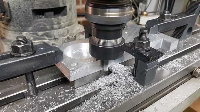 20200906_130720 20200906_130720 by Roger Froud, on Flickr ... and putting them back when it was past allowed it to be done in one pass. Not exactly ideal, but it's good enough.  20200906_163438 20200906_163438 by Roger Froud, on Flickr The two idlers will have flanges and needle roller bearings, but getting the belt just right around the whole assembly so that the adjustment slots are about right might prove to be a problem. I measured it, but these things have a habit of not being spot on when you actually fit the belt. So instead, I've machined two plain plastic bushes which fit directly over the Shoulter Bolts so I can check the fit. I've made them 1mm over size to start with, and I can turn them down on a 10mm bolt to get just the right fit with the motor at the extreme end of the slot. 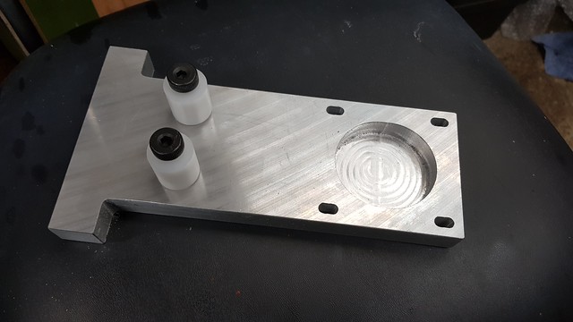 20200906_214621 20200906_214621 by Roger Froud, on Flickr Originally I was going to use round spacers for the motor mount, but I found an ideal piece of Aluminium Alloy bar to make a one piece version which I think is more elegant and will act as a guard. I will need to 3D print some dust covers to keep the swarf out of the belt too. I'm using an 18mm Carbide Milling Cutter which has just enough flute length to reach the full depth.  20200906_173423 20200906_173423 by Roger Froud, on Flickr  20200906_195220 20200906_195220 by Roger Froud, on Flickr Almost roughed out. It won't take long to finish that tomorrow.  20200906_214408 20200906_214408 by Roger Froud, on Flickr |
|
|
|
Post by springcrocus on Sept 6, 2020 22:15:53 GMT
More progress on the 4th Axis for the mill today... ... These hold the side plates that keep the belt on the pulley. 20200905_214324 by Roger Froud, on Flickr With tongue firmly in cheek, I might suggest that a slight doming on the outside of the pulley negates the need for side plates. The belt beomes self-centering.
Regards, Steve
|
|
|
|
Post by Roger on Sept 6, 2020 22:27:52 GMT
More progress on the 4th Axis for the mill today... ... These hold the side plates that keep the belt on the pulley. 20200905_214324 by Roger Froud, on Flickr With tongue firmly in cheek, I might suggest that a slight doming on the outside of the pulley negates the need for side plates. The belt beomes self-centering.
Regards, Steve
Hi Steve, I was wondering about that myself. To be honest, the ones that come on the small pulley would probably be enough on their own. You know me though, I'll probably fit them anyway, I'm a glutton for more work than is strictly necessary. |
|
|
|
Post by andyhigham on Sept 7, 2020 14:44:31 GMT
The usual arrangement for toothed belts is to have flanges on the smaller pulley only. If you have flanges on both you wouldn't be able to see if the belt was biasing to one side, without flanges the belt would be seen to be running off the pulley so could be re-aligned
|
|
|
|
Post by Roger on Sept 7, 2020 14:52:07 GMT
The usual arrangement for toothed belts is to have flanges on the smaller pulley only. If you have flanges on both you wouldn't be able to see if the belt was biasing to one side, without flanges the belt would be seen to be running off the pulley so could be re-aligned I might leave them off, it will depend on how it tracks when I try it. It's easy to add them if it looks like it might benefit from them. Looking at the HPC Gears Catalogue, they are all supplied with flanges. I imagine people mix and match them and have flanges on all of the pulleys unless you're trying to drive the cost down. |
|
|
|
Post by andyhigham on Sept 7, 2020 19:33:53 GMT
I suppose the belt in this situation will get an easy life.
I have a 30mm wide 8mm pitch belt transmitting over 85bhp with a small pulley speed up to 12000 rpm. Lasted 1 1/2 seasons of hard thrashing and dumping the clutch from a standing start with the engine screaming
|
|
|
|
Post by Roger on Sept 7, 2020 20:37:01 GMT
I finished the profile of the motor spacer and added the fixing holes, so that just needed cutting off then finishing in the lathe. 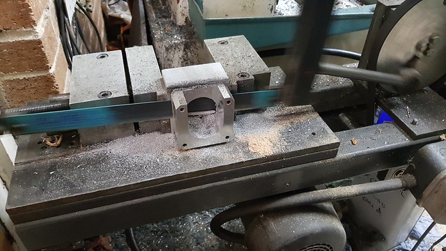 20200907_102921 20200907_102921 by Roger Froud, on Flickr  20200907_212406 20200907_212406 by Roger Froud, on Flickr It's a bit blurry, but you get the idea.  20200907_104653 20200907_104653 by Roger Froud, on Flickr I dismantled the main shaft because swarf was going to get into the bearings when I did these machining operations.  20200907_122918 20200907_122918 by Roger Froud, on Flickr I'm impressed with the build quality of this, it's very nicely made.  20200907_124259 20200907_124259 by Roger Froud, on Flickr There are mounting holes on the other side of the casting too.  20200907_144035 20200907_144035 by Roger Froud, on Flickr The tooth profile is being machined with a 1mm ball nosed cutter.  20200907_151359 20200907_151359 by Roger Froud, on Flickr I should have waited for the belt to arrive so I could check this. Hopefully it's right or I'll have to start again. Each tooth takes about five minutes to machine. I'm up to 94 degrees at this point.  20200907_212714 20200907_212714 by Roger Froud, on Flickr |
|
|
|
Post by Roger on Sept 7, 2020 22:02:01 GMT
Baldric has very kindly pointed me to the correct Works Drawing No. 126897 for the 8X injector, which can be bought from Didcot for the princely sum of £6. It's money well spent, because this injector is significantly smaller than the 10X even though the flanges appear to be the same sizes and offsets from the body diameter. When I adjusted the body length to the figure Baldric gave me yesterday, it looked too chunky. The body and end diameters are a lot smaller, which hopefully brings this back into proportion. So here's the real thing again...  DSCN5687 DSCN5687 by Roger Froud, on Flickr ... and my interpretation of the drawing. (Edit - It looks like the overflow flange is too low...)  8X injector assembly 8X injector assembly by Roger Froud, on Flickr I've taken liberties with the position of the curved inlet water pipe, it's 0.5mm further away from the end than it should be to give a little more room for the thread. You'll also notice that I've changed the three rows of holes in the cones to a single row of the size required for the necessary gap.  8X injector sectioned assembly 8X injector sectioned assembly by Roger Froud, on Flickr |
|
dscott
Elder Statesman
Posts: 2,438
|
Post by dscott on Sept 7, 2020 23:43:51 GMT
The smaller injector once perfected will look lovely on the smaller classes of 4500 and 5700 etc.
Well worth going for.
Not to mention 1366!!!
I am gearing up for another 12 mm plate-work milling session once they are all cut roughly to size.
The 1500 plates need a step of 3mm each side to make the bottoms of the horns by the ashpan.
I did one and worked out so well for the Simplex rework as a Fowler Complex.
Mass production as they are all the same width.
Again like the use of O rings above. Often a sit back and a CAN THIS BE DONE A BETTER WAY Session
often results in vast improvements.
David and Lily.
|
|
|
|
Post by Roger on Sept 8, 2020 21:24:39 GMT
Ok, that was a bit tedious, but it's done now. I hope the belt fits!  20200908_211944 20200908_211944 by Roger Froud, on Flickr Each tooth took about 5 minutes to machine because I had to use the main spindle and it's nowhere near fast enough. I could have done it in a third of the time if the rotary table didn't foul the motor drive of the high speed spindle. I might make a new adaptor and fit the other belt driven high speed spindle that I've got. Still, that's a project for another day. Anyway, I thought I'd finish this even if the belt isn't the best of fits. I'll use this one to finish the 4-th axis and then use that to machine a better one.  20200908_212013 20200908_212013 by Roger Froud, on Flickr |
|
|
|
Post by Roger on Sept 9, 2020 21:50:10 GMT
I painted this a couple of days ago, but forgot to post the picure. I think there was a partial blockage in the vent in the cap because I struggled to get enough paint on in time. I'll have to watch out for that next time. However, it's covered reasonably well but could use a second coat. At least it hasn't made a terrible mess around the small rivets. Yeah, I know they won't be seen, but I want to make a half decent job of it. Anyway, I think it's almost hard enough to lightly rub it down with wet I dry so I can finish it off. I resisted doing the buffers at the same time. I'll do them with it stood on its end like Chris Vine shows in his book. It will take longer, but being able to see what you're doing is fundamental to having a chance of getting a decent finish.  20200907_212043 20200907_212043 by Roger Froud, on Flickr |
|


