|
|
Post by Roger on Oct 14, 2020 21:59:01 GMT
This is the clack cover for the injector outlet. I need a clack on the injector that shares the same top feed as the Axle Pump. The other one doesn't need one, but it will probably get one anyway. There's very little room because the pipe diameters are larger than scale, as is the valve. I've managed to shoehorn in a 1mm section 'O' ring and there's just two turns of M6 x 0.75 (fine) thread. In anything other than Phosphor Bronze, that would be hopelessly weak, but I think it will be ok. 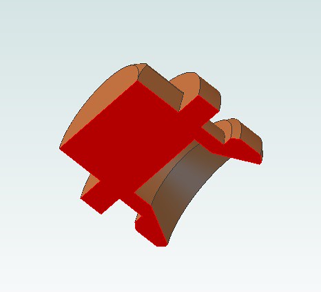 Clack cover section Clack cover section by Roger Froud, on Flickr  Clack cover Clack cover by Roger Froud, on Flickr So here I've screw cut the thread and turned the rest of the details...  20201014_223138 20201014_223138 by Roger Froud, on Flickr ... then used the tailstock to tightly screw on my standard Mild Steel Female bush I have for each size. Note that I've roughed out the hex diameter leaving about 0.2mm over the corners so there's as little material to remove as possible on the mill since I can't really tighten the thread that much.  20201014_223749 20201014_223749 by Roger Froud, on Flickr The assembly was then parted off. I'll snip off the parting knob and face it off then machine the hex. I'll do that when the second Overflow Valve has fininshed on the mill.  20201014_223953 20201014_223953 by Roger Froud, on Flickr |
|
|
|
Post by Roger on Oct 17, 2020 22:38:55 GMT
Continuing with the Clack cover, this is a wobbly video of the machining of the hex. I'm only using 0.1mm deep cuts so that the forces don't unscrew the thread.  20201017_093553 20201017_093553 by Roger Froud, on Flickr I had to slightly ease the 4.5mm socket spanner that I made some time ago since it was a bit tight. That was used to release the part from the threaded bush. 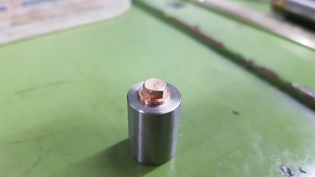 20201017_205235 20201017_205235 by Roger Froud, on Flickr And this is how it looks on the injector.  20201017_212309 20201017_212309 by Roger Froud, on Flickr It's pretty small, but the thread doesn't need to do anything other than stop the cover from being pushed out. The seal is on the diameter of the 'O' ring groove.  20201017_212350 20201017_212350 by Roger Froud, on Flickr |
|
|
|
Post by jon38r80 on Oct 18, 2020 8:59:59 GMT
I think somebody made the comment before but it's more like making fine jewellery than engineering. I don't think my hands on the controls of my mill would let me make such a thing without dents, nicks and a pile of broken cutters. There is no doubt CNC is the way to go for fine work unless you have better eyesight than me and the patience of Job
|
|
|
|
Post by Roger on Oct 18, 2020 9:13:21 GMT
I think somebody made the comment before but it's more like making fine jewellery than engineering. I don't think my hands on the controls of my mill would let me make such a thing without dents, nicks and a pile of broken cutters. There is no doubt CNC is the way to go for fine work unless you have better eyesight than me and the patience of Job Hi Jon, Tiny cutters are very difficult to use on a manual machine. Even if you could move the table slowly enough, you would be bored to tears keeping that up for hours and you'd surely make a mistake. Obviously you wouldn't be able to move two axes in synchronism either. So yes, CNC is the way to go for fine work, but the benefits extend well beyond that. Many folk seem to think that CNC is mostly useful for repeat work, but as you can see, much of what I do is one offs. It's not for everyone, but I can't imagine ever going back because it makes life so much simpler and maintaining high levels of accuracy is effortless. |
|
|
|
Post by jon38r80 on Oct 18, 2020 9:18:13 GMT
I was sold on CNC a long time ago by Hoss (in America ) whom I came across when researching the idea on the internet. sadly I don't have the budget or time to convert my Warco mill. It by coincidence is almost exactly the same as the Grizzly mill he converted. I don't think I could justify the expense on a use basis either as I have far too many other Hobbies that wouldn't use it.
|
|
|
|
Post by Roger on Oct 18, 2020 9:44:38 GMT
I was sold on CNC a long time ago by Hoss (in America ) whom I came across when researching the idea on the internet. sadly I don't have the budget or time to convert my Warco mill. It by coincidence is almost exactly the same as the Grizzly mill he converted. I don't think I could justify the expense on a use basis either as I have far too many other Hobbies that wouldn't use it. It's certainly not cheap if you want something that's reasonably chunky. Mine was done just because I really fancied doing it, having been involved in designing CNC machines for the PCB industry. However, it soon became clear that I could use it to do commercial jobs that would have been out of the question before. So although it wasn't converted for commercial use, it's more than paid for itself. I realise that I'm very fortunate to be able to have such lovely toys. |
|
|
|
Post by 92220 on Oct 18, 2020 10:03:08 GMT
Trouble with taking on CNC is that not only do you have to learn to use the CNC machine, but you also have to learn suitable 3D CAD, which, unfortunately I'm too set in my ways, using 2D to spend time at it.....unless somebody has come up with a way of using 2D with CNC!!
Bob.
|
|
millman
Part of the e-furniture

Posts: 297 
|
Post by millman on Oct 18, 2020 10:39:59 GMT
Not strictly true, 2d cad is perfectly suitable for CNC, it is only when you get to very complicated shapes that you would need 3D cad. I have been using Autocad R14 for at least the past fifteen years along with Dolphin Cad Cam and have great success, I am now learning 3D since Alibre bought out their Atom 3D package.
|
|
|
|
Post by Roger on Oct 18, 2020 10:42:45 GMT
Trouble with taking on CNC is that not only do you have to learn to use the CNC machine, but you also have to learn suitable 3D CAD, which, unfortunately I'm too set in my ways, using 2D to spend time at it.....unless somebody has come up with a way of using 2D with CNC!! Bob. Hi Bob, The difference between 2D and 3D is much smaller than you imagine. Everything I've modelled has been done using 2D sketches. The only real difference is that you decide where those sketches are placed. You can chose any existing face and then draw a 2D sketch on it. Alternatively, you can create a new plane to draw on, which is at some distance or angle from and existing feature. Once you've drawn your sketch, most of the time you're just stretching that 2D sketch to add more material of that cross section, or punching a hole through what's already there at that cross section. It really is that simple. I think what intimidates most people is the perceived complexity of what's produced in the final rendering. In reality, the cleverness and complexity is the domain of the Software Engineer who created the package. The user gets all of that for very little knowledge or input. Basically put, if you can use 2D CAD then it's a very small step to being able to use 3D. However, the benefits of 3D CAD should not be underestimated. You get your 2D drawings created for you automatically, and updated whenever you change the model. You get a permanent 3D record of whole assemblies that enables you to check and visualise the complete thing with very little effort. Even if I didn't use CNC, I'd still use 3D modelling, it's a huge help in the design and documentation process. |
|
JonL
Elder Statesman
 WWSME (Wiltshire)
Posts: 2,911
|
Post by JonL on Oct 18, 2020 14:49:12 GMT
My spirit is willing but the budget is weak! However things being brought in from china does drive costs down all the time, and over time more will appear on the second hand market so I can make the jump.
|
|
|
|
Post by Roger on Oct 18, 2020 20:52:44 GMT
This is the output end fitting for the injector. The thread is screw cut M7 x 0.75 (fine) with a 1.1mm wide 'O' ring groove.  20201017_225140 20201017_225140 by Roger Froud, on Flickr That had my standard threaded bush screwed tightly on using the tailstock chuck, and then parted off. 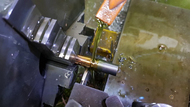 20201017_231016 20201017_231016 by Roger Froud, on Flickr That was then turned ready for the hex to be added...  20201017_232248 20201017_232248 by Roger Froud, on Flickr ... and then returned to the lathe for finishing the hex chamfer and round the corner of the body.  20201018_121229 20201018_121229 by Roger Froud, on Flickr 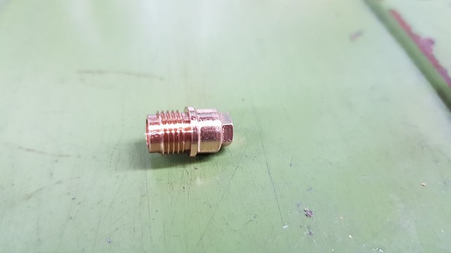 20201018_122100 20201018_122100 by Roger Froud, on Flickr So both the input and output ends are almost done, just a little adjustment to get the nip on the 'O' ring right. I also need a 5.5AF box spanner to tighten it up, so I've designed one of those for making tomorrow.  20201018_214446 20201018_214446 by Roger Froud, on Flickr |
|
|
|
Post by Deleted on Oct 19, 2020 7:24:54 GMT
That looks superb Roger...nice work sir.
Pete
|
|
|
|
Post by Roger on Oct 19, 2020 11:38:37 GMT
A quick update on the sorry tale of the painting. This looked fine when I did it...  20201018_125436 20201018_125436 by Roger Froud, on Flickr ... but even though I turned it over several times, it's sagged. Not only that, I can see that there's still some witness around the rivets where I'd sprayed the primer using the other setup. So, that's just come off back to the bare metal so I can have another go. It appears to me that you have to spray this sort of thing with the gun absolutely perpendicular to the face, else you get a ring around the rivets. That's not possible if the part is stood on its end because of the design of the spray gun. It would appear that the best strategy is to paint if on its side and then stand it on its end to flat out and dry. I'd love to have been able to spray it on the spit, but you just can't get enough access on the end. I did consider making an arrangement to let me do that, and I might still decide to go down that road. We'll see.  20201019_114021 20201019_114021 by Roger Froud, on Flickr |
|
|
|
Post by 92220 on Oct 19, 2020 13:00:05 GMT
Trouble with taking on CNC is that not only do you have to learn to use the CNC machine, but you also have to learn suitable 3D CAD, which, unfortunately I'm too set in my ways, using 2D to spend time at it.....unless somebody has come up with a way of using 2D with CNC!! Bob. Hi Bob, The difference between 2D and 3D is much smaller than you imagine. Everything I've modelled has been done using 2D sketches. The only real difference is that you decide where those sketches are placed. You can chose any existing face and then draw a 2D sketch on it. Alternatively, you can create a new plane to draw on, which is at some distance or angle from and existing feature. Once you've drawn your sketch, most of the time you're just stretching that 2D sketch to add more material of that cross section, or punching a hole through what's already there at that cross section. It really is that simple. I think what intimidates most people is the perceived complexity of what's produced in the final rendering. In reality, the cleverness and complexity is the domain of the Software Engineer who created the package. The user gets all of that for very little knowledge or input. Basically put, if you can use 2D CAD then it's a very small step to being able to use 3D. However, the benefits of 3D CAD should not be underestimated. You get your 2D drawings created for you automatically, and updated whenever you change the model. You get a permanent 3D record of whole assemblies that enables you to check and visualise the complete thing with very little effort. Even if I didn't use CNC, I'd still use 3D modelling, it's a huge help in the design and documentation process. Thanks Roger. Perhaps I'll have to try again. Back when I was last an engineering design draughtsman, I worked constantly with Autocad 2004 3D. It was great. Unfortunately my licence ran out on Acad2004 just a year ago. I tried to get it relicenced but Autodesk said they had just stopped supporting that version the PREVIOUS WEEK and so couldn't re-instate the licence!! And there was no way I was going to pay for a current licence that is payable monthly, and ends up paying them £thousands over just a couple of years, so I decided to stick with my AcadLT 2013 2D CAD. I used to work in solid modelling all the time, as a draughtsman, and found it easy. Working with Fusion 360 is no help as it is totally different to the main Acad 3D system that I learned. I've also tried a couple of the other freebies out there, but couldn't get on with them either. I will have to try again, perhaps when I have finished re-making the boiler clothing and backhead.....after finding a major c***-*p with the shaping around the firebox corners. Bob. |
|
|
|
Post by delaplume on Oct 19, 2020 13:04:33 GMT
Hi Roger,
Oh dear----yes, you can see that run quite clearly....
My friend ( The Mik Ado ) says}--- "The answer is sublime, you shall achieve in time, to make the "punishment" fit the "crime", etc.......in other words yes, having a horizontal face is ideal but you can't always have it that way so give some thought to altering the spray gun if you can OR.... maybe another type of gun would do the job ??
Here's a thought}---- make a few practice pieces out of some thin, hard cardboard ( No need to waste metal ) .... get a couple of tinned spray paint ( Matt dries quicker than gloss ) and take time-out to try those different ideas before committing actual paint to loco....
Keep at it !!
Alan
|
|
|
|
Post by Roger on Oct 19, 2020 16:14:56 GMT
Hi Bob, The difference between 2D and 3D is much smaller than you imagine. Everything I've modelled has been done using 2D sketches. The only real difference is that you decide where those sketches are placed. You can chose any existing face and then draw a 2D sketch on it. Alternatively, you can create a new plane to draw on, which is at some distance or angle from and existing feature. Once you've drawn your sketch, most of the time you're just stretching that 2D sketch to add more material of that cross section, or punching a hole through what's already there at that cross section. It really is that simple. I think what intimidates most people is the perceived complexity of what's produced in the final rendering. In reality, the cleverness and complexity is the domain of the Software Engineer who created the package. The user gets all of that for very little knowledge or input. Basically put, if you can use 2D CAD then it's a very small step to being able to use 3D. However, the benefits of 3D CAD should not be underestimated. You get your 2D drawings created for you automatically, and updated whenever you change the model. You get a permanent 3D record of whole assemblies that enables you to check and visualise the complete thing with very little effort. Even if I didn't use CNC, I'd still use 3D modelling, it's a huge help in the design and documentation process. Thanks Roger. Perhaps I'll have to try again. Back when I was last an engineering design draughtsman, I worked constantly with Autocad 2004 3D. It was great. Unfortunately my licence ran out on Acad2004 just a year ago. I tried to get it relicenced but Autodesk said they had just stopped supporting that version the PREVIOUS WEEK and so couldn't re-instate the licence!! And there was no way I was going to pay for a current licence that is payable monthly, and ends up paying them £thousands over just a couple of years, so I decided to stick with my AcadLT 2013 2D CAD. I used to work in solid modelling all the time, as a draughtsman, and found it easy. Working with Fusion 360 is no help as it is totally different to the main Acad 3D system that I learned. I've also tried a couple of the other freebies out there, but couldn't get on with them either. I will have to try again, perhaps when I have finished re-making the boiler clothing and backhead.....after finding a major c***-*p with the shaping around the firebox corners. Bob. Hi Bob, I think the answer is to embrace Fusion360 and accept that it's different to what you know. I know that doesn't sound like an attractive proposition, but it's probably the most satisfactory one. If you just slavishly follow some tutorials and accept that it's different from what you're used to, I'm sure you'll quickly get to grips with it. People who haven't used it before seem to pick it up quickly, so the issue is really your expectations about how it ought to work being misaligned with how it actually works. There's a very good reason why Autodesk abandoned AutoCad, and that was the user interface. I looked at it and SmartSketch years ago, and they were chalk and cheese. I'm sure you know it well and it all makes sense to you, but I'd suggest that it's much less user friendly to new users than Fusion360. I'm facing the same issues, in as much as I'm probably going to ditch Alibre Design at some point in the future in favour of fusion360. I too have downloaded it, and it's completely unfamiliar and hard for me to use because I know Alibre Design. However, I'll persist with it when the need arises and have no doubt that it will become equally familiar and easy to use after a little while. |
|
|
|
Post by Roger on Oct 19, 2020 16:18:54 GMT
Hi Roger, Oh dear----yes, you can see that run quite clearly.... My friend ( The Mik Ado ) says}--- "The answer is sublime, you shall achieve in time, to make the "punishment" fit the "crime", etc.......in other words yes, having a horizontal face is ideal but you can't always have it that way so give some thought to altering the spray gun if you can OR.... maybe another type of gun would do the job ?? Here's a thought}---- make a few practice pieces out of some thin, hard cardboard ( No need to waste metal ) .... get a couple of tinned spray paint ( Matt dries quicker than gloss ) and take time-out to try those different ideas before committing actual paint to loco.... Keep at it !! Alan Hi Alan, I do give the gun a couple of goes on something before spraying, but you never get exactly the same result when you spray for real. I'll crack it in the end, it will just take a little patience. |
|
|
|
Post by Roger on Oct 19, 2020 21:43:31 GMT
I made the two box spanners today which are 5mm and 5.5mm AF, made from 8mm Silver Steel. The hex pocket was drilled under size and the hex machined with a 1mm cutter, including the relief on each corner point of the hex. So here are the end caps firmly screwed into position...  20201019_214910 20201019_214910 by Roger Froud, on Flickr ... ready for spotting through so I can see where the cutouts need to be to let the water and steam through. I don't like this sort of design, but there's simply no way to get everything inside the scale body without resorting to this. The far end with the clack is easy, but this end is more tricky because the steam channel is curved away from the end of the injector. However, I drew the largest diameter circle that would go through the bend with the drill set so it touches the back of the channel. I've used the wobbler to find the middle of the fixture in X & Y and trusted that it was right.  20201019_214654 20201019_214654 by Roger Froud, on Flickr You can just make out the witness, so that's what I'll use to line them up for machining the cutout.  20201019_215052 20201019_215052 by Roger Froud, on Flickr Thoughts have returned to how I'm going to test the injectors, and if you recall, I bought this piece of 6" Seamless pipe offcut from my local Steel Stockholder. I was going to use 8mm, but he only had 10mm so that's what I've got! This is very long because I thought I was going to use an immersion heater. However, on buying one of those, it was clear that it wasn't suitable because the joints were soft soldered and the end plate was large and not that thick. 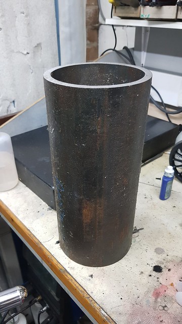 20201019_221509 20201019_221509 by Roger Froud, on Flickr Chatting to Ed about this, he suggested that a coffee machine might have a more suitable element, and he was dead right. These operate at much higher pressures, 9-15Bar, and are much more sturdily made. They come in all shapes, sizes and prices, but this one on eBay looked to be ideal. It's 1800Watts, nice and compact and a snip at £24.99. I've looked at using Cartridge Heaters in a sleeve, but the cost it prohibitive and I'd prefer the element to be in contact with the water. So this is really just a rugged version of a bog standard immersion heater, complete with a temperature probe position which I suppose I could use as a further safety device. We'll see.  20201019_215243 20201019_215243 by Roger Froud, on Flickr Anyway, the boiler can now be a lot shorter, 200mm in total length, and this is the sort of thing I have in mind. The weld preps are 7mm deep and there's bound to be some penetration beyond that. I could make them even bigger, but this is never going to fail at the sort of pressure I'm using. The good thing about these enormous wall thicknesses is that it's dead easy to attach the safety valves, pressure gauge and water level gauge. I'll have to add a blowdown valve too, and of course there will be a clack.  Test boiler section Test boiler section by Roger Froud, on Flickr So thanks to Ed, I'm moving again on this stalled part of the project and I'm looking forward to getting on with it. |
|
|
|
Post by jon38r80 on Oct 20, 2020 11:54:14 GMT
A quick update on the sorry tale of the painting. This looked fine when I did it... 20201018_125436 by Roger Froud, on Flickr ... but even though I turned it over several times, it's sagged. Not only that, I can see that there's still some witness around the rivets where I'd sprayed the primer using the other setup. So, that's just come off back to the bare metal so I can have another go. It appears to me that you have to spray this sort of thing with the gun absolutely perpendicular to the face, else you get a ring around the rivets. That's not possible if the part is stood on its end because of the design of the spray gun. It would appear that the best strategy is to paint if on its side and then stand it on its end to flat out and dry. I'd love to have been able to spray it on the spit, but you just can't get enough access on the end. I did consider making an arrangement to let me do that, and I might still decide to go down that road. We'll see. 20201019_114021 by Roger Froud, on Flickr its always tempting to spray that little bit more when an area isnt quite covered to your liking, looks fine when you do it but when you look at it later - disaster. thinner coats and a bit of drying time between has been more successful for me. First car I repainted I got curtains which is just a description for a large are of runs, It taught me a lot.
I like the dinky spanners, I have some sockets with handles I bought in HK when I lived there for working on RC cars they get brought out every once in a while.
|
|
|
|
Post by suctionhose on Oct 20, 2020 12:04:16 GMT
Interesting work going on there Roger!
On injectors and the preference for thin steam cone / annular regulation in mini injectors: I speculate minimisating metal in this area may be important to promote condensation of the steam. A body of metal or a short exposure time may retain heat that the tiny volume of water has difficulty absorbing in addition to fully condensing the steam entering the injector. Just speculation - no tests to prove either way. Your injector is revolutionary - will be exciting to see!
On your buffer beam: runs happen! You don't have to go back to bare metal; just wet and dry on a block to remove the high spots and a light spray to restore the gloss.
On painting around rivets: it is hard to get the spray to go right in to the edge - ground effect or something. Light coats, 45 deg to surface from 3 or 4 different directions around the compass seems to give the best result - no shadow or lee side remaining. If the coat looks like getting heavy, stop. let it dry. Lightly rub it back and go again. Tedious to rub around rivets - I remember doing a green engine 4 times before I was happy!
Check back on you later!
|
|


