|
|
Post by Roger on Oct 20, 2020 13:21:46 GMT
Interesting work going on there Roger! On injectors and the preference for thin steam cone / annular regulation in mini injectors: I speculate minimisating metal in this area may be important to promote condensation of the steam. A body of metal or a short exposure time may retain heat that the tiny volume of water has difficulty absorbing in addition to fully condensing the steam entering the injector. Just speculation - no tests to prove either way. Your injector is revolutionary - will be exciting to see! On your buffer beam: runs happen! You don't have to go back to bare metal; just wet and dry on a block to remove the high spots and a light spray to restore the gloss. On painting around rivets: it is hard to get the spray to go right in to the edge - ground effect or something. Light coats, 45 deg to surface from 3 or 4 different directions around the compass seems to give the best result - no shadow or lee side remaining. If the coat looks like getting heavy, stop. let it dry. Lightly rub it back and go again. Tedious to rub around rivets - I remember doing a green engine 4 times before I was happy! Check back on you later! Hi Ross, Thanks for that, I trust you're safe and well. Looking at all of Bob Bramson's designs, he uses End Regulation on all of them without any apparent issues. It would be interesting to see if what you suggest makes a difference. It would also be interesting to know who came up with Thin Steam Cones with Annular Regulation, because it doesn't appear to be prevalent in large injectors. To my way of thinking, they're nowhere near as easy to make or as long lasting as flat nosed cones. I presume that others have just followed on rather than try something different. I could see a problem with the undercoat on the buffer beam, with a witness around the rivets. That's the only reason I took it back to bare metal. The thought of rubbing down around rivets fills me with dread, you must be more patient than I am. I hope to hit it in one coat and leave it at that, like I've done elsewhere. |
|
|
|
Post by Roger on Oct 20, 2020 21:40:30 GMT
I've been looking at possible options for the light spring on the overflow valve, and found these on eBay whic are 0.2mm Stainless Steel wire, 4mm OD and 5mm high. They're on a long delivery though, but I need to build the test boiler before then so it's not a problem. Fitting that in is tricky since there's not much room. However I can gain another 1mm of length by making a spherical seat for the ball and letting the spring come up further. I've shown the spring in the uncompressed state, so it looks a bit wrong. There's room to potentially let the ball further up into the body too, but I won't do that unless absolutely necessary. I don't know if the spring is going to be too strong. I'll have to experiment with that. I'm not sure what effect it will have if the spring it too strong. I suspect it will prevent the injector from starting.  Sectioned injector with overflow valve spring Sectioned injector with overflow valve spring by Roger Froud, on Flickr Anyway, here are the cutouts being added to the end caps. This was originally going to be done from the end, but it's easier to set it up on the side and I can get hold of it more firmly.  20201020_154107 20201020_154107 by Roger Froud, on Flickr The cutter is pretty blunt, but it's strong so I thought I'd use it anyway.  20201020_192840 20201020_192840 by Roger Froud, on Flickr  20201020_211911 20201020_211911 by Roger Froud, on Flickr This is the little cover for the bottom of the overflow valve. The spring goes in the pocket and there's a 1.6mm through hole for the rod. There's no seal, just like the real thing so it will dribble if there's water coming out of the overflow. However, the bulk of the water will go down the pipe. Obviously this has the potential to end up clogged with scale, so a bit of maintenance will be necessary to keep it clean.  20201020_211811 20201020_211811 by Roger Froud, on Flickr This is how that looks on the overflow valve body.  20201020_212956 20201020_212956 by Roger Froud, on Flickr |
|
jma1009
Elder Statesman

Posts: 5,901
|
Post by jma1009 on Oct 20, 2020 21:54:47 GMT
I've used end regulation for a new steam cone on one injector as per Bob Bramson. It replaced an annular regulation Steam cone, and works extremely well.
The problem isn't that which Ross quite rightly comments on, but of extrapolating Bob's scant details to other sizes of injectors.
I am not too sure that Roger's assertion that end regulation in full size was common is correct. It is an historic topic fraught with patent rights etc that often ignore the best way of making these gadgets to avoid infringing patents!
From memory, the Penberthy injectors in fullsize use end regulation. I am struggling to recall from memory other full size examples of end regulation.
Cheers,
Julian
|
|
|
|
Post by Roger on Oct 20, 2020 22:40:24 GMT
I've used end regulation for a new steam cone on one injector as per Bob Bramson. It replaced an annular regulation Steam cone, and works extremely well. The problem isn't that which Ross quite rightly comments on, but of extrapolating Bob's scant details to other sizes of injectors. I am not too sure that Roger's assertion that end regulation in full size was common is correct. It is an historic topic fraught with patent rights etc that often ignore the best way of making these gadgets to avoid infringing patents! From memory, the Penberthy injectors in fullsize use end regulation. I am struggling to recall from memory other full size examples of end regulation. Cheers, Julian Hi Julian, That's interesting that you managed to make End Regulation work in an injector designed for Annular Regulation. When you work it all out from Bob's book, you end up with a much shorter Condensing Cone because there's a section of the cone upstream with Annular Regulation that gets in the way. There is almost enough information in the book to design any size of injector, at least those covered in the graphs and tables, but the process is far from clear. According to Bob, the setting of the regulation gap has to be done by adjusting the gap in a particular sequence to get the required performance. Unfortunately, this is omitted from the book. I'll update the Designing Injectors thread when I've finished making mine. I've used D.A.G Brown's book to calculate the regulation area for the designs he details in the centrefold of his book, and used that to calclulate what it needs to be for End Regulation. Hopefully that will end up being close for the first trial. If you look at the 10x and 8x injectors, they seem to be a half way house between End and Annular Regulation. the regulation gap is huge in full size injectors though, so comparisons of the proportions don't really help us much. However, the Steam Cone on those doesn't go down to a knife edge, there's a really large bell mouth on the entry to the Condensing Cone and the nose of the Steam Cone stops short of it. |
|
|
|
Post by Roger on Oct 21, 2020 19:13:27 GMT
Here's one of the two safety valves for the test boiler which uses the same 'soft pop' dimensions used on 1501. I could buy these, but they'll be imperial sizes which I loathe if they come from the UK and they're not cheap. I'd just as soon make my own, it won't take long. It also gives me the opportunity to use 'O' ring seals everywhere which makes it so much easier to make Steam tight.  Safety valve sectioned Safety valve sectioned by Roger Froud, on Flickr |
|
JonL
Elder Statesman
WWSME (Wiltshire)
Posts: 2,907
|
Post by JonL on Oct 21, 2020 20:05:55 GMT
I've defaulted to using copper washers but you are right about the o-rings; I really should make my 16mm locomotive boiler fittings using them. Do you use an o-ring with the same outside diameter as the root diameter of the bush thread?
Sorry to derail your post. I'll make a seperate one if this looks like a big subject!
|
|
|
|
Post by Roger on Oct 21, 2020 20:24:23 GMT
I've defaulted to using copper washers but you are right about the o-rings; I really should make my 16mm locomotive boiler fittings using them. Do you use an o-ring with the same outside diameter as the root diameter of the bush thread? Sorry to derail your post. I'll make a seperate one if this looks like a big subject! I usually go say 0.1mmm under the root diameter so I can screw cut into it without damaging the sealing diameter. |
|
|
|
Post by Roger on Oct 22, 2020 19:30:43 GMT
Not very thrilling, but here's a clack for the test boiler, complete with 'O' ring seals. 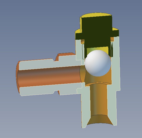 Clack assembly Clack assembly by Roger Froud, on Flickr |
|
|
|
Post by coniston on Oct 22, 2020 19:57:31 GMT
Hi Roger, Assuming this is the final design, wont the ball get stuck up in the cap? I would have less lift and either a central pin poking down or a slotted cage in the top cap so the steam can act on the ball. As it is the cavity above the ball will when full of water, hold the ball up.
Chris D
|
|
|
|
Post by Roger on Oct 22, 2020 20:15:42 GMT
Hi Roger, Assuming this is the final design, wont the ball get stuck up in the cap? I would have less lift and either a central pin poking down or a slotted cage in the top cap so the steam can act on the ball. As it is the cavity above the ball will when full of water, hold the ball up. Chris D Hi Chris, Good point, I might have to make the hole in the cap shorter so it stops the ball going up as far. |
|
|
|
Post by coniston on Oct 22, 2020 20:25:08 GMT
Hi Roger, Gordon Smith did an interesting article on check valves in EIM January 2015, not sure how I got a copy maybe just an internet search but if you want I can email the .pdf to you if you pm your email address.
Chris D
|
|
Gary L
Elder Statesman
Posts: 1,208
|
Post by Gary L on Oct 22, 2020 22:25:23 GMT
Hi Roger, Gordon Smith did an interesting article on check valves in EIM January 2015, not sure how I got a copy maybe just an internet search but if you want I can email the .pdf to you if you pm your email address. Chris D Ha! I’ve got that article too. I think it might have come from Roger!  Gary |
|
|
|
Post by Roger on Oct 23, 2020 7:07:59 GMT
Hi Roger, Gordon Smith did an interesting article on check valves in EIM January 2015, not sure how I got a copy maybe just an internet search but if you want I can email the .pdf to you if you pm your email address. Chris D Ha! I’ve got that article too. I think it might have come from Roger! Gary Hi Gary, It's possible, I've got so much I've squirreled away, I honestly don't know everything that I have! |
|
|
|
Post by Roger on Oct 24, 2020 14:36:45 GMT
Another disheartening spraying session, with slightly too little paint on the near side that makes it slightly less glossy than the rest. I can also see the witness of a spot where I had to add filler plus some places where the rings around the rivets show a little. From a step back and out of the light it looks ok, but it's not very good. I'll have to wait for it to completely dry so I can rub it back and have a go at a second coat. I really dislike not being able to turn this over while I'm spraying it, with the ever present risk of a run. It looked pretty uneven when I stood it on its end after spraying, but it did flatten out considerably when it was left for ten minutes. It makes me wonder if I need to spray it at a slightly higher pressure to atomise the paint better and put it on a bit quicker.  20201024_152418 20201024_152418 by Roger Froud, on Flickr |
|
|
|
Post by chris vine on Oct 24, 2020 21:27:26 GMT
Hi Roger,
On your buffer beam problem:
Apart from a general problem getting the gloss to flow (without running), you seem to be having trouble with rings round rivets.
I think this may be caused by the sharpish corner where rivet meets beam. Maybe there is even an undercut there?
Can you spray primer fairly thinly so that it goes into the corner and goes tacky before flowing out. I feel there is a surface tension fight going on around the rivets - so nothing to do with where you spray the paint from. If it is fluid enough to flow, then it is flowing in a way you don't like. IE (I think) being pulled by the adjacent surfaces (beam and dome of rivet) away from the internal corner around the rivet.
I feel you need to fix this problem with primer and then sparing coats of coloured coat.
Then, when you do the heavy gloss coat so that it pulls out without leaving a ripple, there is already a small radius in the bottom of the groove round the rivet. Also, if it does pull away a bit, you won't notice it so badly because there will already be a coloured layer underneath. Mostly though, I think the small radius in the bottom from the earlier coats will fix it for you.
As for runs, I think you should be fine with it flat as you show in the picture. maybe you can build up the coat with several passes. Maybe another few passes every minute (eg).
Hope this helps!
Chris.
|
|
|
|
Post by Roger on Oct 24, 2020 22:02:55 GMT
Hi Roger, On your buffer beam problem: Apart from a general problem getting the gloss to flow (without running), you seem to be having trouble with rings round rivets. I think this may be caused by the sharpish corner where rivet meets beam. Maybe there is even an undercut there? Can you spray primer fairly thinly so that it goes into the corner and goes tacky before flowing out. I feel there is a surface tension fight going on around the rivets - so nothing to do with where you spray the paint from. If it is fluid enough to flow, then it is flowing in a way you don't like. IE (I think) being pulled by the adjacent surfaces (beam and dome of rivet) away from the internal corner around the rivet. I feel you need to fix this problem with primer and then sparing coats of coloured coat. Then, when you do the heavy gloss coat so that it pulls out without leaving a ripple, there is already a small radius in the bottom of the groove round the rivet. Also, if it does pull away a bit, you won't notice it so badly because there will already be a coloured layer underneath. Mostly though, I think the small radius in the bottom from the earlier coats will fix it for you. As for runs, I think you should be fine with it flat as you show in the picture. maybe you can build up the coat with several passes. Maybe another few passes every minute (eg). Hope this helps! Chris. Hi Chris, Thanks for all that, I'll take a look when it's properly gone off. I'm not sure how bad it is until I look really closely. I don't like to go anywhere near the room when it's still tacky in case it causes dust issues. I'll probably end up stripping it off yet again! If I do that, I'll probably make an arrangement to allow me to turn it while it's all horizontal, that seems to make life so much easier. It's either that or make an adaptor to hold the paint reservoir a 90 degrees to the nose so I can spray vertically. I've managed to spray the cladding and smokebox in one coat, so I can't see why I can't do this that way too. You're probably right about the edges of some of the rivets though, that might need attention. |
|
|
|
Post by Roger on Oct 24, 2020 22:21:55 GMT
The reverse side of all of the flanges needed recesses for 4mm or 5mm copper pipe, so I machined a pocket in a piece I've used for many other fixtures.  20201024_223630 20201024_223630 by Roger Froud, on Flickr The pockets are only 0.5mm deep, but it's enough to locate them when Silver Soldering  20201024_220024 20201024_220024 by Roger Froud, on Flickr So here they all are, three Steam flanges, three Outlet flanges and two Inlet water flanges. I only need two Inlet water flanges because one of the Injectors connects directly to the 90 degree elbow which has a flange already. There are three sets, two for the Injector connections on the locomotive, and one set for the test boiler.  20201024_231138 20201024_231138 by Roger Froud, on Flickr |
|
|
|
Post by Roger on Oct 24, 2020 22:28:35 GMT
Now I don't need such a long test boiler for the injectors, having sourced a better immersion heater, I'm cutting it down to 250mm long. This is my home made power hacksaw, built from scrap metal and a couple of recirculating bearings salvaged from a Dentist's chair at the scrap yard. It could use to be a bit more rigid, but it saves a lot of hard work. 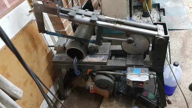 20201024_160857 20201024_160857 by Roger Froud, on Flickr That's still longer than it needs to be for the element, but I don't want to go too small and suffer from running out of Steam while testing by having too small a volume. So this is how much I've removed.  20201024_232433 20201024_232433 by Roger Froud, on Flickr |
|
|
|
Post by Roger on Oct 25, 2020 9:50:27 GMT
This is the top and bottom water gauge fitting, using the same 2mm section 'O' ring arrangement for sealing the 5mm glass as used on the locomotive. There's no adjustment, it relies on the flexibility of the large section 'O' ring which seals radially. The nut is just to contain the 'O' ring so it can't blow out. I don't plan on having blow down or shut off valves. 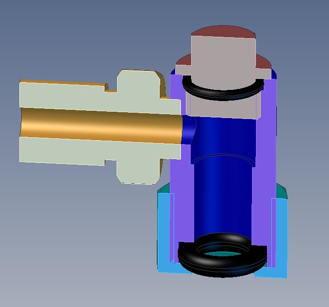 Water gauge fitting Water gauge fitting by Roger Froud, on Flickr |
|
oldnorton
Statesman
 5" gauge LMS enthusiast
Posts: 693
|
Post by oldnorton on Oct 25, 2020 10:42:52 GMT
If you mean on the bottom of the gauge, then you will need a blow down to demonstrate that you can clear the glass during the Steam Test. I cannot state whether this is a written test requirement but more than one inspector has asked me to do this. It is also a definite safety aid in checking the water level. Norm |
|


