|
|
Post by Roger on Nov 13, 2020 13:44:31 GMT
I use blunt end mills/slot drills to make little and not so little boring bars, a good source of HSS or carbide. Hi Paul, That's a very useful idea, I do this on occasion too for very small holes. I've got a little holder I made for 1/8" shanks so I can use 2-flute PCB carbide cutters as boring bars with a little grinding to lose the second cutting edge. Those aren't anywhere near as robust as these boring bars though. |
|
|
|
Post by racinjason on Nov 13, 2020 20:30:31 GMT
Roger,
I use Picco brand miniature carbide boring, grooving and threading in both the lathe and mill there not cheap but very nice.
Regards Jason.
|
|
|
|
Post by Roger on Nov 13, 2020 21:55:52 GMT
Roger, I use Picco brand miniature carbide boring, grooving and threading in both the lathe and mill there not cheap but very nice. Regards Jason. Hi Jason, Those were some of the ones I looked at. I've used MSC for my EasyChange tooling system. All great quality industrial tools, but mighty expensive. I did also find this one on eBay which is one of those. I liked what I saw, but didn't want to tie myself into a type that was so expensive. If I could have seen more on eBay of this type, I might have gone for it. Hopefully the ones from Banggood will be ok and then I'll have a ready supply at a reasonable price. |
|
|
|
Post by Roger on Nov 13, 2020 22:14:59 GMT
Here's the finished end profile on the Blowdown valve. Doug kindly gave me the 12mm carbide long series cutter for hardened materials which was ideal for this long reach and Stainless material.  20201113_120216 20201113_120216 by Roger Froud, on Flickr I drilled the Banjo bolt hole to 6mm to give the 8mm end mill an easier time and then opened it out to 10mm...  20201113_154422 20201113_154422 by Roger Froud, on Flickr ... so it could be offered up to the 4-jaw chuck on the lathe on a piece of studding. There's no significance to it being studding, it just fitted the hole nicely.  20201113_155609 20201113_155609 by Roger Froud, on Flickr That was clocked up and opened out to the clearance size for the bolt and then undercut in the middle for the Steam clearance. I turned it round and did the same for the other side so that the clearance was to 12mm on a 10mm bolt which will be plenty.  20201113_155908 20201113_155908 by Roger Froud, on Flickr Then it was back to the mill for the exit hole and register for the pipe.  20201113_174728 20201113_174728 by Roger Froud, on Flickr Since the body is Stainless, I didn't want the threaded part to be Stainless too, so that's PB102 Here's it's been made 3mm too long so that I can add a centre. I wanted to do it this way round so I could offer the thread up to the body to make sure the fit was right.  20201113_204653 20201113_204653 by Roger Froud, on Flickr Then the end chamfer was added in the right place, leaving a pip to clean up later.  20201113_205121 20201113_205121 by Roger Froud, on Flickr Click on the image below to see a wobbly video of the 4th axis being used to machine the 5mm AF hex on the shaft. I've created a little program that indexes six times back and forth in the Y-axis, indexing 60 degrees after each pass. The idea is that I can measure the AF size and then move the Z-axis to get the correct size. There's no X or Z-axis moves in the program, just the cutting pass and index. This will be a standard program used for all of this type of operation.  20201113_214502 20201113_214502 by Roger Froud, on Flickr |
|
|
|
Post by Roger on Nov 14, 2020 22:06:33 GMT
This is the gland for the Blowdown Valve being made from Brass since it doesn't have to be very strong.  20201114_121618 20201114_121618 by Roger Froud, on Flickr That's getting the usual treatment of parting off having been attached to the M10 x 1 (fine) standard Steel piece. That was faced off and the hex added on the mill.  20201114_121909 20201114_121909 by Roger Froud, on Flickr I knocked up the Delrin split sleeve to hold the shaft for finishing off the ends.  20201114_133902 20201114_133902 by Roger Froud, on Flickr  20201114_134540 20201114_134540 by Roger Froud, on Flickr  20201114_141716 20201114_141716 by Roger Froud, on Flickr  20201114_141440 20201114_141440 by Roger Froud, on Flickr The outlet was TIG welded on. It's not pretty, but it's not important.  20201114_175741 20201114_175741 by Roger Froud, on Flickr I had a piece of Copper rod to make the two Banjo washers from which were heated to Red heat and quenched to remove the scale. And finally here's all that fitted to the boiler. The gland may seem over the top, but I want to leave this on the bench and blow it down using a Silicone pipe out through the door, and I don't want it spraying out of the shaft hole while that's happening. 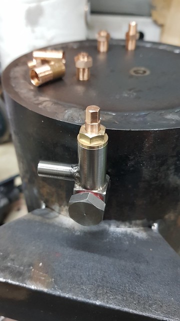 20201114_200129 20201114_200129 by Roger Froud, on Flickr This is the body of the first of the two Safety Valves, again in Stainless Steel because I've got some in a handy size.  20201114_215324 20201114_215324 by Roger Froud, on Flickr |
|
|
|
Post by Roger on Nov 15, 2020 21:38:01 GMT
This is the 3/16" reamed hole for the seat in the Safety Valve. It's an Imperial size because I'm using a GWR 'soft pop' design I bought the plans for from Polly Models. 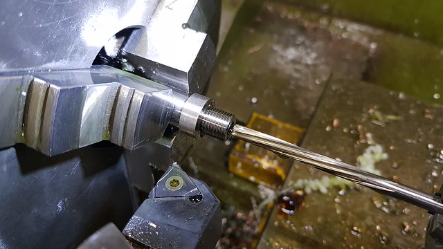 20201115_123835 20201115_123835 by Roger Froud, on Flickr The only operation required on the Mill was to add the Hex.  20201115_135708 20201115_135708 by Roger Froud, on Flickr I don't know what I was thinking of when I made these from Phosphor Bronze... actually I wasn't really thinking at all, just avoiding Stainless Steel. I should have made them from Brass, it would have been a lot easier, especially when it came to tidying up the threads after parting off and cleaning up the through holes.  20201115_202545 20201115_202545 by Roger Froud, on Flickr Anyway, they're done now. So there's just the ball holder stem piece to make and then these are done too.  20201115_213055 20201115_213055 by Roger Froud, on Flickr |
|
|
|
Post by David on Nov 15, 2020 22:00:11 GMT
Beautiful as always! Why did you have the piece of steel screwed onto the gland while parting it off?
|
|
|
|
Post by Roger on Nov 15, 2020 22:45:35 GMT
Beautiful as always! Why did you have the piece of steel screwed onto the gland while parting it off? Thanks David. The answer is that it's easier to tightly screw the Steel piece on before it's parted off than when there's only a short length to get hold of. The next operation is to face it off to length and then machine the Hex on the mill. The problem with holding it by the thread is that whichever way you machine it, ie climb or conventional milling direction, the rotation of the cutter tends to unscrew the piece. That's why I like to do it up pretty tightly. On really small parts in difficult materials, such as Phosphor Bronze, I'll often use very small cuts to make sure it never comes undone. Sometimes there's only a very short length of thread, and then I take even lighter cuts. Of course, once the hex has been machined, you can use that to unscrew it. |
|
|
|
Post by Roger on Nov 16, 2020 21:45:08 GMT
Here's the second of the two ball holders for the Soft Pop Safety Valve being made from Phosphor Bronze because the shaft is only 2.4mm diameter and not very strong. This is an ideal use for the new tool holder because it's so easy to create the sharp shoulders. I've made this 3mm longer than the drawing so that I can have a 3mm deep centre in the end. When I set this up, I touch the end with the tool and then set the Z-axis DRO to +3mm so I can still use the dimensions on the drawing as if they were from the end. Those were then parted off and turned round for finishing. I'll complete that and show it tomorrow. The extra 3mm can then be cut off, or in this case I probably won't bother.  20201116_205857 20201116_205857 by Roger Froud, on Flickr |
|
|
|
Post by Roger on Nov 17, 2020 10:44:43 GMT
The face of the ball holder needs to be drilled so that the ball stand out between 1.905 and 2.032mm (converted from imperial sizes) To check that I've zeroed the tailstock DRO with the closed chuck pressed against the face. I've then inserted the ball and read off the distance. Both of them were within the tolerance on first drilling so that's good since the balls don't want to come out! I'd have to bond something to them to pull them out.  20201117_102049 20201117_102049 by Roger Froud, on Flickr Anyway, here they are finished, so that's the Safety Valve parts complete other than to press a ball into the seat and assemble them.  20201117_103437 20201117_103437 by Roger Froud, on Flickr |
|
|
|
Post by Roger on Nov 18, 2020 16:41:30 GMT
Ok this is a commercial job, but it's relevant to ME too. This video shows a piece of HSS in the vice which I'm machining with a worn out PCB burr to make a Form tool. The tool was originally made from Gauge Plate which was hardened and tempered. However, I need it to last longer than it currently does, even though I'm going slowly and keeping it cool. HSS is a much better material for the job, but not as easy to machine. Anyway, rather than beat up a load of new cutters I thought I'd use the High Speed Spindle and see whether it's feasible to machine it with cutters that cost me nothing. I'm only taking 0.1mm cuts because the cutter has 10mm of cutting length and isn't that strong. It does appear to be a viable solution though, and I'll certainly be using this idea again for Form tools that are going to get a hard time.  20201118_163156 20201118_163156 by Roger Froud, on Flickr |
|
|
|
Post by 92220 on Nov 18, 2020 19:08:14 GMT
Hi Roger.
Thanks for that info. Well worth considering HSS if I need any more form tools! I must admit, using, and machining, HSS had not crossed my mind before reading your post above!!
Bob.
|
|
dscott
Elder Statesman

Posts: 2,438
|
Post by dscott on Nov 19, 2020 0:55:50 GMT
 During the summer I had a much resharpened endmill in the mill doing 2 bits of rusty rail for my display track. Flat bottomed out of 1/2 inch square. Now to make it rust quickly! DONE months later! While the cutter is in it is perfect for the famous I beam as fitted to 1500 Locomotives. Here is one of them sanded down to remove the cutter marks and painted to see the effect. Side 2 to do on a rainy day when not building Christmas Trees and Workshop Extensions. David and Lily. |
|
|
|
Post by Oily Rag on Nov 19, 2020 21:46:47 GMT
During the summer I had a much resharpened endmill in the mill doing 2 bits of rusty rail for my display track. Flat bottomed out of 1/2 inch square. Now to make it rust quickly! DONE months later! While the cutter is in it is perfect for the famous I beam as fitted to 1500 Locomotives. Here is one of them sanded down to remove the cutter marks and painted to see the effect. Side 2 to do on a rainy day when not building Christmas Trees and Workshop Extensions. David and Lily. |
|
dscott
Elder Statesman
Posts: 2,438
|
Post by dscott on Nov 20, 2020 0:29:09 GMT
YES?
Form tools. High speed cutters. 1500 Locomotives. I beam as fitted. 12 by 12 mm steel. 2 cut out as I was doing similar stuff.
Mass of own drawings. 200 photos of 1501 plus. Two to scale models being built.
Via the Paddington Design. 5 inch gauge.
Traveled behind 1501 many enjoyable times. She is quite bouncy. Especially on the last run of the weekend and they are late back to the RACE COURSE at Cheltenham!!!
Also seen at Didcot. Mid Hants. And Severn valley where she lives.
She also has a Facebook group which grows about 4 members a day.
David and Lily.
|
|
|
|
Post by Roger on Nov 20, 2020 23:42:18 GMT
Progress has unfortunately been at a standstill this week because commercial work has kept me and the machines tied up. All of the fittings that needed to be Silver Soldered were screwed into the boiler and rings of 1.5mm Silver Solder wire were formed to closely hug the location diameter. The registers are only 1.5mm deep, but enough to press fit the parts in the right position so they tighten up at the right point. This is the first one, with the threads, hex and body covered in Tippex and the joint fluxed. I'm doing it in this orientation so that the Silver Solder has gravity on its side, even though I can't see what's happening. I heated it pretty quickly to a noticeable Red heat so I was certain that the Silver Solder had melted.  20201120_224356 20201120_224356 by Roger Froud, on Flickr The one on the left has had 15 minutes in the ultrasonic tank. Other than that, it hasn't been touched. The others are cooling down.  20201120_225947 20201120_225947 by Roger Froud, on Flickr It looks like the Tippex inside has stopped the Silver Solder messing with the internal threads and ball seats, and there's a generous fillet of Silver Solder around the joints. It's way too much really, but I thought the small wire would be too little. Anyway, it's a good step forward, one that can go horribly wrong, so I'm pleased with the outcome.  20201120_233044 20201120_233044 by Roger Froud, on Flickr |
|
|
|
Post by Roger on Nov 21, 2020 15:15:51 GMT
I've been looking at the balanced test valves in the D.A.G Brown and Bob Bramson books and concluded that I can design something simpler and more appropriate for my use. If you haven't see this idea before, it's basically a clack valve. However, instead of Steam pressure, there's a piston that holds the valve closed. So on this model, the water delivered from the Injector on test enters on the LH side. The RH end is connected to steam at boiler pressure. The free floating piston with the O-ring is therefore being pushed left by the boiler pressure on the RH end, pressing against the ball. The key thing is that the diameter of the piston is the same as the diameter where the ball seats. This means that the Injector has to reach boiler pressure before it opens, but when it does, it opens to atmospheric pressure at the outlet. The idea is that you can test the injector without putting the delivery water into the boiler. You can also collect and measure how much water would be delivered.  Balanced test valve assembly Balanced test valve assembly by Roger Froud, on Flickr I've created three lobes in the ball chamber to keep the ball somewhere near the middle so it doesn't block the outlet hole. It's all pretty small, the ball is only 6mm diameter and the piston and entry holes are 4mm diameter. I'm not planning on using this on very large injectors, just ones typical of 5" Gauge locomotives. The designs I've seen are much larger, but that makes sense since the designers want to test a wide range of sizes.  Balanced test valve body Balanced test valve body by Roger Froud, on Flickr |
|
|
|
Post by mr swarf on Nov 21, 2020 18:48:37 GMT
Hi Roger,
Just going back to the safety valve, should there be a locking ring? Anyone know if there are any regs about this.
Paul
|
|
JonL
Elder Statesman
WWSME (Wiltshire)
Posts: 2,909
|
Post by JonL on Nov 21, 2020 19:01:26 GMT
I'm not aware of any locking ring requirement. Also this boiler isn't being steamed in public.
|
|
|
|
Post by Roger on Nov 21, 2020 19:16:52 GMT
Hi Roger, Just going back to the safety valve, should there be a locking ring? Anyone know if there are any regs about this. Paul Hi Paul, Good thought. As far as I'm aware it isn't required. I suspect that's because if it moves, it's only going to move upwards. |
|


