|
|
Post by andyhigham on Nov 28, 2020 21:39:29 GMT
Are you heat treating them before the finishing grind?
It was something I was taught as an apprentice during my rotation inn the tool room. The final grinding removes distortion caused during the heat treatment
|
|
|
|
Post by Roger on Nov 28, 2020 21:45:15 GMT
Are you heat treating them before the finishing grind? It was something I was taught as an apprentice during my rotation inn the tool room. The final grinding removes distortion caused during the heat treatment No, they're HSS so there's no need for heat treatment. I'm just splitting the roughing and finishing operations so guarantee the wheel is true. |
|
JonL
Elder Statesman
 WWSME (Wiltshire)
Posts: 2,909
|
Post by JonL on Nov 29, 2020 11:14:22 GMT
I've yet to make a d-bit of any kind. I suppose I should as it's a useful skill!
|
|
|
|
Post by Roger on Nov 29, 2020 20:43:31 GMT
This is the setup for grinding the Taper Reamers for the Injectors in half. I didn't want to use coolant because it goes everywhere, so instead I set up an air line. I know it's nowhere near as effective, but it's good enough. 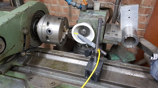 20201129_114544 20201129_114544 by Roger Froud, on Flickr It still got to about 300C, but it doesn't matter since it's HSS. I stopped when I was about 0.1mm from the finished size, trued the wheel, found the positon with a feeler gauge between the wheel and the cut, then carried on. The final size was determined by the measurement on the parallel section to the flat.  20201129_114557 20201129_114557 by Roger Froud, on Flickr I've added a 1micron resolution Digital Plunger type clock on the Tool & Cutter Grinder so I can accurately make cuts. You just have to remember that it's the Radius you're adjusting when you're grinding a diameter!  20201129_202943 20201129_202943 by Roger Froud, on Flickr Anyway, I did both ends of the reamers, so that's another job done.  20201129_161706 20201129_161706 by Roger Froud, on Flickr I needed to add a small chamfer on the lead in to the O-ring seating on the boiler barrel. I want these to be at 30 degrees, so I decided to make a simple tool to cut those. This is just a piece of Steel with an M10 x 1 (fine) thread and a parallel 8mm diameter...  20201129_164836 20201129_164836 by Roger Froud, on Flickr ... which is used as the guide for this Silver Steel cutter. This is just a tube with a tooth standing clear of the surface. I set the piece with a 0.2mm runout in the lathe to give the clearance.  20201129_163936 20201129_163936 by Roger Froud, on Flickr This is how it look on the barrel. I used my large chuck from the lathe to hold it and apply the cutting force.  20201129_163921 20201129_163921 by Roger Froud, on Flickr I'd slightly messed up on how deep the chamfer was, so I had to grind it a bit deeper.  20201129_163510 20201129_163510 by Roger Froud, on Flickr Anyway, I'd very pleased with the result.  20201129_164816 20201129_164816 by Roger Froud, on Flickr The Safety Valves hadn't had the ball pressed into the seat, so I made this Delrin sleeve to take a hardened dowell that was an appropriate size.  20201129_171829 20201129_171829 by Roger Froud, on Flickr That was put in the vice to press it firmly home. Note that I'm using Silicone O-rings for these.  20201129_171745 20201129_171745 by Roger Froud, on Flickr They fitted nicely without any further adjustment, so the seals ought to be good. I'll adjust the pressures later.  20201129_175728 20201129_175728 by Roger Froud, on Flickr The Steam Valves were then set up on the manifold and the position of the outlet was marked with a centre punch. Those were set up in the Mill and the hole and register were machined. 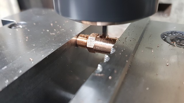 20201129_175716 20201129_175716 by Roger Froud, on Flickr I just need to finish the outlet flanges so they fit tightly into the register. It's only 1mm deep, so they may not stay put. If it's a problem, I'll use a Toolmaker's clamp to hold them while Silver Soldering. |
|
|
|
Post by Roger on Nov 30, 2020 13:00:27 GMT
Having machined the registers in the Steam Valve bodies, this is one of the outlet unions mated to the Steel holder so it can be parted off and the mating register turned.  20201130_105756 20201130_105756 by Roger Froud, on Flickr  20201130_111244 20201130_111244 by Roger Froud, on Flickr I formed two Silver Solder rings which turned out to be too thick, so they stopped the register being pushed fully home in the register. Those were crushed in the vice to make them thin enough.  20201130_112433 20201130_112433 by Roger Froud, on Flickr That allowed them to be pushed firmly home, so I smothered them with Tippex to keep the Silver Solder up close to the joint and protect the threads from the blow torch. Those were then fluxed...  20201130_114829 20201130_114829 by Roger Froud, on Flickr 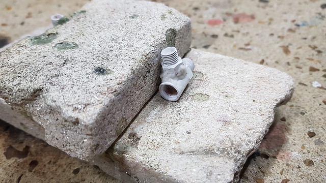 20201130_114837 20201130_114837 by Roger Froud, on Flickr ... and heated to a dull Red until I could see that the rings had melted.  20201130_115041 20201130_115041 by Roger Froud, on Flickr  20201130_115049 20201130_115049 by Roger Froud, on Flickr Again, there is more Silver Solder than necessary, but it's nice and strong.  20201130_124702 20201130_124702 by Roger Froud, on Flickr |
|
|
|
Post by Roger on Nov 30, 2020 22:34:46 GMT
I found the piece of Tufnol that I'd used to make the fake wooded handles for the Locomotive. It was miles too big for that job, but ideal for this one. Here's the trial fit for the handle on the shaft hex. 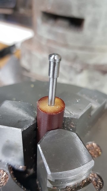 20201130_203415 20201130_203415 by Roger Froud, on Flickr The outside may as well have a grippy shape. 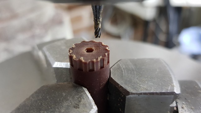 20201130_210134 20201130_210134 by Roger Froud, on Flickr Finally assembled with all the 'O' rings.  20201130_215301 20201130_215301 by Roger Froud, on Flickr This is the Balanced Test clack valve getting the seat formed by the 6mm Silicon Nitride ball.  20201130_213443 20201130_213443 by Roger Froud, on Flickr That's also finished. I trimmed a little more off the inside diameter of the 'O' ring on the plunger to reduce the friction. That might still need a shade more, but I'll try it like this first.  20201130_213819 20201130_213819 by Roger Froud, on Flickr This is the final orientation I've settled on for the manifold. The middle one will be for the Pressure Gauge. 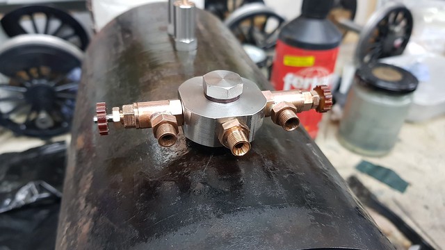 20201130_222235 20201130_222235 by Roger Froud, on Flickr |
|
|
|
Post by Cro on Dec 1, 2020 6:57:40 GMT
Looking good!
I forgot to ask. Where are you fitting a pressure gauge for your balanced valve? The DAG brown version has it fitted on the injector delivery side so you can see the delivery pressure of the injector.
Adam
|
|
|
|
Post by Roger on Dec 1, 2020 8:39:26 GMT
Looking good! I forgot to ask. Where are you fitting a pressure gauge for your balanced valve? The DAG brown version has it fitted on the injector delivery side so you can see the delivery pressure of the injector. Adam Hi Adam, I wasn't going to bother. I know it must at least be at boiler pressure, unless the valve is stuck open. I can always fit one using a Tee piece if I want to do that. For me, the main purpose of the balanced valve is to simulate boiler pressure while avoiding filling the boiler with water. Perhaps the gauge is fitted because the friction in the balanced valve piston gives a raised pressure. I can always take the 'O' ring out if that's an issue. There won't be a huge amount of steam passing the little piston, and that would guarantee it's genuinely balance. We'll see, I might fit one if it's not clear what's going on. The main thing is to be able to run the Injector to see if it works properly. |
|
|
|
Post by Roger on Dec 1, 2020 18:03:35 GMT
Following John's suggestion, I'm effectively parting off the Gauge Glass using a broken PCB Carbide drill that's been ground to a point and in half. The glass was surprisingly easy to machine. I got well over half way through the wall thickness before it broke off cleanly.  20201201_154633 20201201_154633 by Roger Froud, on Flickr The end has a nice chamfer, so I just used a Diamond needle file to remove the sharp edges.  20201201_155340 20201201_155340 by Roger Froud, on Flickr |
|
|
|
Post by Roger on Dec 1, 2020 21:55:04 GMT
I've fitted the Water Gauge for a pressure test, but the clacks still need the 5mm Silicon Nitride balls. I thought I had some of those, but apparently I haven't, so I've ordered some on a fairly short delivery.  20201201_212539 20201201_212539 by Roger Froud, on Flickr The pressure gauge has an 1/8" BSPT thread and a flat back, so I've put a parallel die down that and added a 60degree location for a pipe union. Here's the Brass nut that will attach the union to the Pressure Gauge. 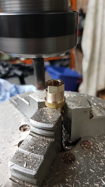 20201201_212633 20201201_212633 by Roger Froud, on Flickr  20201201_212651 20201201_212651 by Roger Froud, on Flickr I'll make a short small bore Copper pipe to connect this up shortly. 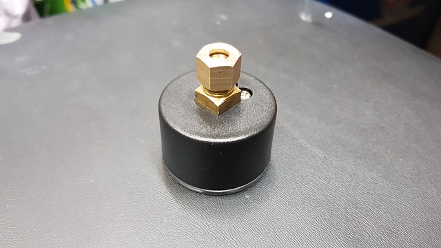 20201201_214411 20201201_214411 by Roger Froud, on Flickr |
|
jma1009
Elder Statesman
Posts: 5,901
|
Post by jma1009 on Dec 1, 2020 22:07:11 GMT
Hi Roger,
As you can imagine I've been following all this with great interest.
You seem to have rather glossed over the making of your injector, and I am sure that forum members would be interested in further details please!
It can't have been that easy, surely, even with your 'kit'?
Or was it?!
My silver steel injector reamers are a real pain to make. And they also blunt on brass after 5 or so uses.
If you have a dead smooth ( or as Arthur Grimmett used to say "smooooth"!) reamers you will get a good finish that is so important for increased range.
Cheers,
Julian
|
|
jma1009
Elder Statesman
Posts: 5,901
|
Post by jma1009 on Dec 1, 2020 22:10:00 GMT
your injector = injector reamers
(Can't seem to edit via my iPhone!)
|
|
|
|
Post by Roger on Dec 1, 2020 22:47:46 GMT
Hi Roger, As you can imagine I've been following all this with great interest. You seem to have rather glossed over the making of your injector, and I am sure that forum members would be interested in further details please! It can't have been that easy, surely, even with your 'kit'? Or was it?! My silver steel injector reamers are a real pain to make. And they also blunt on brass after 5 or so uses. If you have a dead smooth ( or as Arthur Grimmett used to say "smooooth"!) reamers you will get a good finish that is so important for increased range. Cheers, Julian Hi Julian, It's good to hear from you. I did show the reamers getting ground, but it might have been broken up by other posts. The key stages were as follows... 1) Grind a large diameter test piece and keep adjusting the table angle until that grinds parallel. 2) Set the angle DRO to zero degrees, then swing the table to the half angle required. 3) Rough grind the taper, then true the wheel and finish to length. The exact length isn't important so long as it's sufficient. 4) Lock the workhead so it won't turn and set the angle back to zero degrees 5) Use a cup wheel to rough the reamer in half, then true the wheel and grind until the parallel portion is half the diameter of the blank Obviously the fine end is really delicate, so you have to give it time to spark out and take the spring out of the cut. The modified Tool & Cutter Grinder is ideal for this sort of job. Making them using conventional machines would be much more challenging. If I was making a lot of them, I'd probably make the reamers from Carbide drill blanks. I imagine that even the HSS reamers will blunt quite quickly on the Leaded Bronze I've bought for the cones. The real issue is that there's no back clearance on the reamer, meaning that as soon at the cutting edge dulls and recedes even slightly, the land behind the cutting edge stops it from cutting. Hopefully I'll get on to those shortly when the Test Boiler is up and running. |
|
|
|
Post by Roger on Dec 2, 2020 23:03:59 GMT
I'd forgotten to sort out the seat for the clacks, so I've clocked this up while holding the body in the M8 x 0.75 Steel holder...  20201202_114923 20201202_114923 by Roger Froud, on Flickr ... so I could ream the bore to 4mm...  20201202_115029 20201202_115029 by Roger Froud, on Flickr ... which could then have the seat formed. Here's the sleeve and dowel used for that. 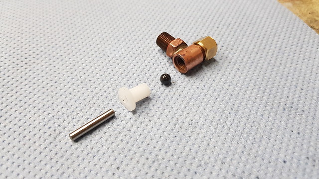 20201202_112722 20201202_112722 by Roger Froud, on Flickr This is the thick Copper tube adaptor for the Pressure Gauge. The hole is 1.6mm diameter because it doesn't need to be large and I want the Pressure Gauge to be supported by it.  20201202_123752 20201202_123752 by Roger Froud, on Flickr So here are the two unions fitted to the pipe with rings of Silver Solder, flux and Tippex to protect the threads. 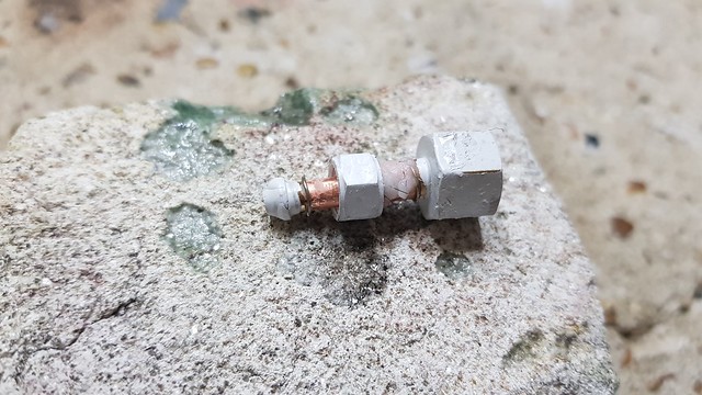 20201202_142421 20201202_142421 by Roger Froud, on Flickr That didn't quite take on the LH end...  20201202_142642 20201202_142642 by Roger Froud, on Flickr ... so I've added a bit more on that end. 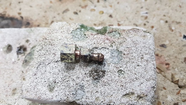 20201202_143433 20201202_143433 by Roger Froud, on Flickr The arrangement is bent up slightly so it drains back to the manifold.  20201202_145531 20201202_145531 by Roger Froud, on Flickr  20201202_145542 20201202_145542 by Roger Froud, on Flickr So it was finally time to see if it's a pressure vessel or a Colander, and the answer is the latter. The clacks weep a little, so they need a little more attention. The Safety Valves also lift too early so the threads in those need making a bit deeper.  20201202_165843 20201202_165843 by Roger Froud, on Flickr The Safety Valve thread is a bit tight, so I've made this tool to make that easy to adjust.  20201202_222150 20201202_222150 by Roger Froud, on Flickr The cross hole is a piece of 6mm Mild Steel, bonded in with Loctite. 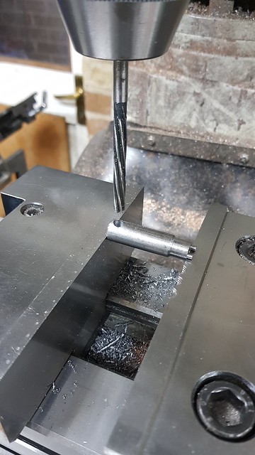 20201202_222912 20201202_222912 by Roger Froud, on Flickr  20201202_224606 20201202_224606 by Roger Froud, on Flickr |
|
dscott
Elder Statesman
Posts: 2,438
|
Post by dscott on Dec 2, 2020 23:29:28 GMT
£130 ? And what is this for, MMM Such a shame she will not be ready for this Christmas. But now we can save up for one at last. NO. I have just returned from the OO section and www.rapidotrains.co.uk where the announcement of a Model of a Little 1500 has just been REVIEALED. What some do is put one of these little ones upon the runn in g bo. I now see a snag not covered by Fredrick. W. Hawksworth with a major flaw in his design. That in the year 2021 People making 5 inch gauge versions, may at last wish to put a OO gauge model upon the running boards for a Photograph. Of course the answer is obvious. For the Photo. 3 D Print one!!! Modern Technology. David and Lily. They have done a CAD Drawing which is worth a closer look. They may have done a 3 D Scan of 1501? There are also some very nice photos and a History. |
|
|
|
Post by Roger on Dec 2, 2020 23:45:55 GMT
£130 ? And what is this for, MMM Such a shame she will not be ready for this Christmas. But now we can save up for one at last. NO. I have just returned from the OO section and www.rapidotrains.co.uk where the announcement of a Model of a Little 1500 has just been reviled. What some do is put one of these little ones upon the runn in g bo I now see a snag not covered by F. W. Hawksworth with a major flaw in his design. That in the year 2021 People making 5 inch gauge versions may at last wish to put a OO gauge model upon the running boards for a Photograph. Of course the answer is obvious. For the Photo 3 D Print one!!! Modern Technology. David and Lily. They have done a CAD Drawing which is worth a closer look. They may have done a 3 D Scan of 1501? Hi David, I presume that was a typo, and that the model was revealed, not reviled! |
|
mbrown
Elder Statesman
Posts: 1,720
|
Post by mbrown on Dec 3, 2020 9:20:16 GMT
I see you haven't used a syphon between the pressure gauge and the manifold. The purpose of the syphon is to ensure that a column of water is always in the pipe so that the gauge is not exposed directly to hot steam. Is your gauge heat-proof up to the temperature of saturated steam?
Malcolm
|
|
|
|
Post by Roger on Dec 3, 2020 9:47:15 GMT
I see you haven't used a syphon between the pressure gauge and the manifold. The purpose of the syphon is to ensure that a column of water is always in the pipe so that the gauge is not exposed directly to hot steam. Is your gauge heat-proof up to the temperature of saturated steam? Malcolm Hi Malcolm, To be honest I have no idea what the gauge will cope with. If it's a problem, I'll make a longer pipe and put a shallow 'U' bend in it. I don't think this one is long enough. The temperature will only be 166C at the maximum pressure, so I suspect it will be fine. Time will tell! |
|
|
|
Post by David on Dec 3, 2020 10:55:59 GMT
So it was finally time to see if it's a pressure vessel or a Colander, and the answer is the latter. The clacks weep a little, so they need a little more attention. The Safety Valves also lift too early so the threads in those need making a bit deeper. Colander may be a bit of a harsh judgement for that list of woes! It's hard to imagine anything would come through those welds though. |
|
pault
Elder Statesman
Posts: 1,496
|
Post by pault on Dec 3, 2020 13:25:06 GMT
I see you haven't used a syphon between the pressure gauge and the manifold. The purpose of the syphon is to ensure that a column of water is always in the pipe so that the gauge is not exposed directly to hot steam. Is your gauge heat-proof up to the temperature of saturated steam? Malcolm Hi Malcolm, To be honest I have no idea what the gauge will cope with. If it's a problem, I'll make a longer pipe and put a shallow 'U' bend in it. I don't think this one is long enough. The temperature will only be 166C at the maximum pressure, so I suspect it will be fine. Time will tell! Hi Malcolm beat me to it. There are two issues, one is that in this day and age a pressure gauge not designed for steam could have plastic parts in it which might not like the temperature. The other, which would apply to most gauges, is that thermal expansion of the bourdon tube will give you an inaccurate reading. I would use a siphon tube personally. Regards Paul |
|


