|
|
Post by Roger on Oct 4, 2021 20:43:16 GMT
A few final details needed finishing, so here I'm adding the E-Clip clearance in the back of the frame support...  20211004_111624 20211004_111624 by Georgia Montgomery, on Flickr ... and the pivot hole in the forked top mount.  20211004_113251 20211004_113251 by Georgia Montgomery, on Flickr This is the top of lug of the top cap...  20211004_145822 20211004_145822 by Georgia Montgomery, on Flickr ... the radius...  20211004_151058 20211004_151058 by Georgia Montgomery, on Flickr ... and fixing hole.  20211004_155829 20211004_155829 by Georgia Montgomery, on Flickr The bottom forked piece is held in place by a pin with a couple of E-Clips  20211004_153927 20211004_153927 by Georgia Montgomery, on Flickr So finally, here's the whole assembly, complete with O-rings but less the springs and Silicone oil. At this point I haven't I haven't drilled any holes in the piston because I want to see how it feels with just the working clearance.  20211004_204816 20211004_204816 by Georgia Montgomery, on Flickr |
|
|
|
Post by 92220 on Oct 4, 2021 22:00:23 GMT
That's really neat Roger!!
Bob.
|
|
|
|
Post by jon38r80 on Oct 4, 2021 22:32:38 GMT
If it wasnt in your hand for scale, you would think it was the real thing (full size I mean)
|
|
|
|
Post by Roger on Oct 5, 2021 7:59:52 GMT
Thanks guys, let's hope it does the job. I can't see why not. It's chunky and strong, so it ought to be able to transmit a sizeable force if needed.
It's a challenge to design it short enough to fit the limited space, so the piston is a bit shorter than I'd like. I may see if it's possible to make that 1mm thicker so that I can fit an O-ring on the piston too. I haven't made the dust cover yet, and that might have to go in preference to the piston modification. We'll see. Ideally I'd like to have both.
Anyway, it's been fun to make, and it will be interesting to see how it affects the springing. My instinct says it's going to make a big difference.
|
|
|
|
Post by Roger on Oct 5, 2021 16:17:33 GMT
The Anti-Roll bar mount needed a small adjustment to accommodate the Hydraulic Damper...  20211005_115250 20211005_115250 by Georgia Montgomery, on Flickr ... so it would fit like this.  20211005_130402 20211005_130402 by Georgia Montgomery, on Flickr This is how it looks with the axle dropped down to the bottom of travel...  20211005_163442 20211005_163442 by Georgia Montgomery, on Flickr ... and you can see just how tight that gets when it's at the other end. I realise now that I won't need a dust cover any more, because the rod comes out at the bottom  20211005_170823 20211005_170823 by Georgia Montgomery, on Flickr I just need to sort out a temporarly spring for the free piston while I wait for the slow boat from China to arrive with the Belleville Washers. |
|
jem
Elder Statesman

Posts: 1,066
|
Post by jem on Oct 5, 2021 16:59:22 GMT
Roger, please tell us what are the 3 half threads in the top of you machine vice are for, as I am sure they must have a purpose. and maybe useful for others.
best wishes
Jem
|
|
|
|
Post by Roger on Oct 5, 2021 20:57:25 GMT
Roger, please tell us what are the 3 half threads in the top of you machine vice are for, as I am sure they must have a purpose. and maybe useful for others. best wishes Jem Hi Jem, I'm afraid that's battle damage. The Mach3 CNC software I used to use had a bug in the backlash compensation feature. That resulted in an offset causing a collision with the vice. The odd pattern is from the features on the part I was machining. That was the grate. |
|
|
|
Post by Roger on Oct 5, 2021 21:50:53 GMT
Looking at the front axle, it looks like I can still use the eccentric I've made for the lubricator if I move it over to one side like this. However, it does foul the bottom fitting on the axle pump, so that will need modifying. The eccentric is the same dimensions as the one for the axle pump, it could be a lot smaller. However, this one is already made, so I might as well use it. It's not a quick job to make another one since it's split in two parts and is fiddly to do. I'll just modify the bottom fitting. I could make the bearing smaller, but I'd rather keep it as big as possible.  20211005_224350 20211005_224350 by Georgia Montgomery, on Flickr |
|
|
|
Post by runner42 on Oct 5, 2021 22:48:48 GMT
Hi Roger, I am sure you will sort the problem out. However, you could utilise the axle pump eccentric to drive both the axle pump and mechanical lubricator as I have done, but no doubt better engineered than mine. Brian  chassis complete7 chassis complete7 by Brian Leach, on Flickr |
|
|
|
Post by Roger on Oct 6, 2021 8:46:10 GMT
Hi Roger, I am sure you will sort the problem out. However, you could utilise the axle pump eccentric to drive both the axle pump and mechanical lubricator as I have done, but no doubt better engineered than mine. Brian chassis complete7 by Brian Leach, on Flickr Hi Brian, That's a really neat solution, something I hadn't considered. There's very little force required, so it's only whether it's convenient to lay it out that way that matters. I'll have a look at that option before making a final decision. It's pretty busy around the pump area with pipes and valves, so it might not be the best solution. Anyway, thanks for that suggestion, it's a good idea. |
|
jem
Elder Statesman
Posts: 1,066
|
Post by jem on Oct 6, 2021 16:13:43 GMT
Roger, so sorry to bring your battle damage to the notice of every one, still it is nice to know that we are not the only ones, I will keep my mouth shut in the future.
very best wishes
Jem
|
|
|
|
Post by Roger on Oct 6, 2021 18:04:07 GMT
Roger, so sorry to bring your battle damage to the notice of every one, still it is nice to know that we are not the only ones, I will keep my mouth shut in the future. very best wishes Jem No problem. It's annoying, because it really wasn't my fault. Such is life! |
|
JonL
Elder Statesman
WWSME (Wiltshire)
Posts: 2,909
|
Post by JonL on Oct 6, 2021 20:26:41 GMT
Roger, so sorry to bring your battle damage to the notice of every one, still it is nice to know that we are not the only ones, I will keep my mouth shut in the future. very best wishes Jem I don't think you should apologise, finally Roger has passed the Turing test! He eats his tea with a CNC fork you know... |
|
|
|
Post by Roger on Oct 6, 2021 20:49:35 GMT
For those who haven't seen this simple idea before, here's my solution to sticking inlet valves on water pumps. This is just a piece of 1mm section O-ring cord in a 1.1mm cross hole just below the seat. It's positioned to just lift the ball so it only touches the seat when water flows in the direction that's trying to close the valve.  20211006_114022 20211006_114022 by Georgia Montgomery, on Flickr You can see the cross hole in this picture more clearly. Anyway, a bit of pruning is required to remove the unwanted union. This was originally added when I thought I'd use a connection from either Side Tank directly to the pump so that it would act as a balance pipe too. Here the fitting is being parted off as close to the body as possible without hitting anything.  20211006_114615 20211006_114615 by Georgia Montgomery, on Flickr A little Brass plug was then turned up and a 'C' shaped piece of 0.5mm Silver Solder wire added. I've covered all of the threads with Tippex...  20211006_120128 20211006_120128 by Georgia Montgomery, on Flickr ... and I'm protecting one of the threads by hiding it behind a brick.  20211006_120449 20211006_120449 by Georgia Montgomery, on Flickr 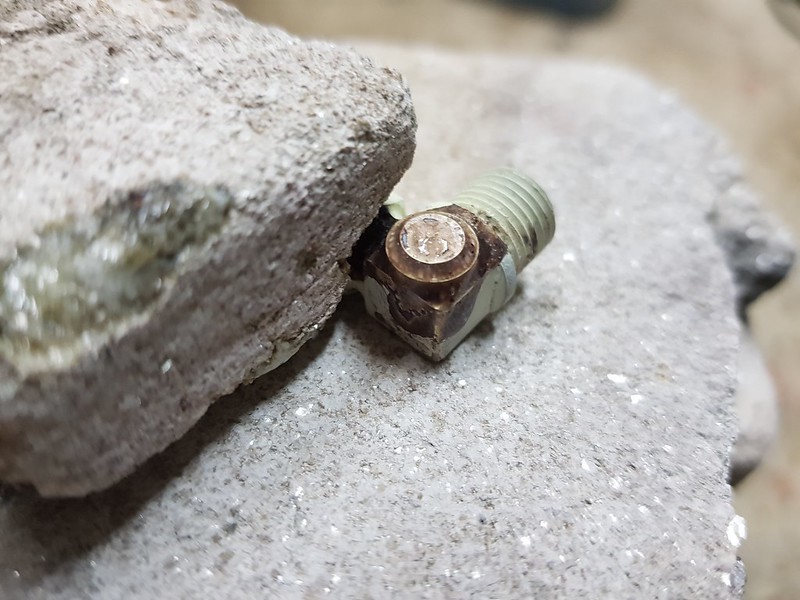 20211006_121024 20211006_121024 by Georgia Montgomery, on Flickr This is how it looks after 20 minutes in the Ultrasonic tank.  20211006_140840 20211006_140840 by Georgia Montgomery, on Flickr There's plenty of clearance now. I just need to fill in the dowel hole I made to locate the eccentric. I don't know why I bothered with it on this one really.  20211006_145802 20211006_145802 by Georgia Montgomery, on Flickr |
|
JonL
Elder Statesman
WWSME (Wiltshire)
Posts: 2,909
|
Post by JonL on Oct 6, 2021 20:58:08 GMT
Your tippex seems to cover better than mine. Is it the new stuff or old stock? Sorry to ask about trivialities
|
|
|
|
Post by Roger on Oct 6, 2021 21:00:11 GMT
Your tippex seems to cover better than mine. Is it the new stuff or old stock? Sorry to ask about trivialities It's not that old, but I do give the bottle a really good thumping shake onto my hand to stir it up when I use it. I need to get some more really, I think this is my last bottle. |
|
dscott
Elder Statesman
Posts: 2,438
|
Post by dscott on Oct 6, 2021 21:54:45 GMT
You can imagine a Huddle of Model Engineers searching for tippex in a stationary Shop.
Only to be told "Its cash only and are you over the age of 18."
Just checked The Range but they don't have tippex...
But type in Correcting Fluid and a pack containing Tipp-ex arrives for £i.99 click and collect or they can send.
David and Lily.
Worthing have a Range.
|
|
|
|
Post by Roger on Oct 6, 2021 22:13:03 GMT
You can imagine a Huddle of Model Engineers searching for tippex in a stationary Shop. Only to be told "Its cash only and are you over the age of 18." Just checked The Range but they don't have tippex... But type in Correcting Fluid and a pack containing Tipp-ex arrives for £i.99 click and collect or they can send. David and Lily. Worthing have a Range. I just bought some from eBay, my one stop shop, £3.89 for two bottles including delivery. |
|
|
|
Post by Roger on Oct 7, 2021 19:57:59 GMT
Having fitted one of the Hydraulic Dampers, I'm confident that this layout is going to work. So this is the second adaptor for the middle axle being finished off...  20211007_085944 20211007_085944 by Georgia Montgomery, on Flickr ... and here's one of the four frame attachment points.  20211007_102738 20211007_102738 by Georgia Montgomery, on Flickr I've now tidied those up, and made all of the pins too.  20211007_204607 20211007_204607 by Georgia Montgomery, on Flickr I think it's a waste of time trying to mess about with springs just to try it out, I'll wait until the correct ones arrive. I'm better off spending the time making the other parts. The Hydraulic Damper for the leading axle can be 5.7mm longer overall than the one on the middle axle. I've modified the body to be that much longer, adding the extra length to the piston thickness and the length of the rod bearing. The front damper will likely experience a little side loading as the shaft tries to rotate the bearing while it's under load. I'm hoping that this won't lead to excessive wear. I could potentially attach the bearing to the axlebox, or have an arrangement to locate the two with a couple of pins. I'll reserve judgement on whether that's sensible or not. The wear on the two parts will likely be different, and that means the location would probably need to accommodate some vertical movement. It can all be done, it's just whether it's really necessary or not. |
|
JonL
Elder Statesman
WWSME (Wiltshire)
Posts: 2,909
|
Post by JonL on Oct 8, 2021 18:10:24 GMT
Define excessive wear? How much do you plan to use it?
|
|


