|
|
Post by Roger on Aug 6, 2022 20:56:30 GMT
The Lamp Irons and spacers on the front have well and truly dried, so here's the LH one fitted to the buffer gusset top...  PXL_20220806_163646489 PXL_20220806_163646489 by Timothy Froud, on Flickr ... and to the RH side too. I've carefully hand painted over the Red bolts that hold the Buffer Stocks in place. They've been machined to make it look like they are bolted from the back with nuts.  PXL_20220806_164017917 PXL_20220806_164017917 by Timothy Froud, on Flickr I also riveted the Lamp Irons onto the Cylinder Wrappers and bolted on the Chequer foot plates. 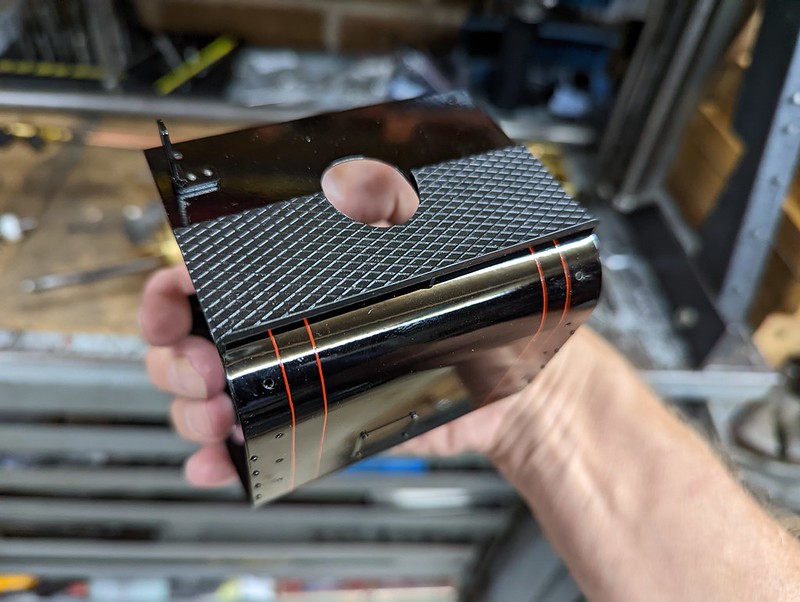 PXL_20220806_203953495 PXL_20220806_203953495 by Timothy Froud, on Flickr Each plate is held on with M1 x 1.8mm long Brass Bolts, shortened from 4mm ones. 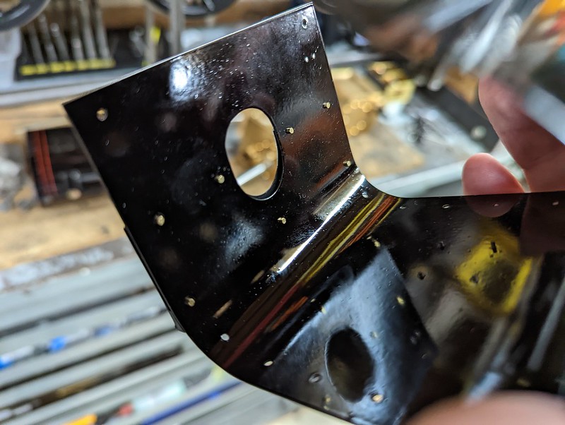 PXL_20220806_204037077 PXL_20220806_204037077 by Timothy Froud, on Flickr I've also attached the bottom bulge which covers the piping from the piston valve chest. These were made from a solid piece of Mild Steel Bar, Silver Soldered to a curved base. There's a location pin and a single M1.6 cap screw from the back.  PXL_20220806_204058798 PXL_20220806_204058798 by Timothy Froud, on Flickr Time consuming, but well worth the effort in my opinion. |
|
|
|
Post by doubletop on Aug 7, 2022 8:05:35 GMT
The ideal temperature for most painting, is 60F (15.5C). Move away from that temp, either way, will cause different problems, but problems that get worse, the further you get, from the ideal temp. Bob. That is encouraging because that was about the temperature I had been getting the workshop to. Although, I don't think the cans got to that temperature and when I used them, I also did notice the temperature of the cans dropped as the gas evaporated. One of my club members said he had been advised to put the spray can in warm water. He then found that the domed end of the can inverted. His adviser then reminded him that he had said warm water, not boiling water. (you try this at your own risk) Meanwhile back to Roger…….. . . Pete |
|
|
|
Post by Roger on Aug 7, 2022 22:38:44 GMT
I'd forgotten that I hadn't spot faced the area where the two M4 Grub Screws bit down on the Piston Valve Liners, so I had to take these apart again. The puller engages with three holes around the outside of the Liners and the Nylon part presses against the face of the cylinder. They're a snug fit, but they come out easily enough like this. It would be a real struggle without a puller.  PXL_20220807_085231807 PXL_20220807_085231807 by Timothy Froud, on Flickr I used the 4th axis because it's convenient when setting up to an angle. I screwed a long M4 cap screw into one of the holes and lined it up with a stack of parallels on the bed. That's plenty good enough for this job.  PXL_20220807_104719783 PXL_20220807_104719783 by Timothy Froud, on Flickr |
|
dscott
Elder Statesman

Posts: 2,438
|
Post by dscott on Aug 8, 2022 1:46:21 GMT
Far too hot to paint today so we avoided anything trains and went on a walk.
Then got to have lunch on the nearest Station to Roger at Christs Hospital.
Lovely work Roger and the red lines superb.
David and Lily.
|
|
|
|
Post by doubletop on Aug 9, 2022 9:51:05 GMT
Roger
It occurred to me that the Midland Show is a couple of months away and you must be pretty close to finishing your Speedy. Do you have any plans to let everybody see it in person and marvel at your efforts?
I ask this because in the 14 months between now and the 2023 show you will have no doubt steamed it. After that it will never look as good as it did prior to the first steaming.
Sadly, I wouldn’t get to see it myself as I’m unlikely to make it, despite having managed something like 4 of the last 6 shows.
Pete
|
|
|
|
Post by Roger on Aug 9, 2022 10:35:09 GMT
Roger It occurred to me that the Midland Show is a couple of months away and you must be pretty close to finishing your Speedy. Do you have any plans to let everybody see it in person and marvel at your efforts? I ask this because in the 14 months between now and the 2023 show you will have no doubt steamed it. After that it will never look as good as it did prior to the first steaming. Sadly, I wouldn’t get to see it myself as I’m unlikely to make it, despite having managed something like 4 of the last 6 shows. Pete Hi Pete, I certainly will show it at some point. I'm really bad at estimating how long jobs take though. I've still got the Pressure Gauges to make and some more Cab Fittings and details around the Pannier Tanks before those things can be painted. There's more to do on the whistle valves and some other bits and pieces on the backhead. I'm starting to get back into it now though after being too busy to get anything done. Hopefully one of our Foster Dogs finds his Forever Home tomorrow, and that will reduce the amount of dog walking I need to do. So whether it will be this next year or the following one is anyone's guess. It does finally feel like I'm approaching the home straight. I'm not going to be too precious about how it looks, nothing stays new for long. |
|
|
|
Post by Roger on Aug 10, 2022 6:03:46 GMT
When I machined the Cylinders, I hadn't realised that the centre drain cock wasn't in the middle, but offset to one side. It's the same casting for both, so it's forward on one side and to the rear on the other. There was a third threaded boss on the casting to take the drain cock, but that had to be machined away so that it could be move to the right place. Fortunately, there's a plate that bridges between the cocks, so I can just make a special nut that makes it look the same as the others. It's getting a hex to help me tighten it, because it's a trivial thing to add when you have CNC.  PXL_20220809_194613147 PXL_20220809_194613147 by Timothy Froud, on Flickr  PXL_20220809_210158100 PXL_20220809_210158100 by Timothy Froud, on Flickr It fits like this, the hex being hidden by the Cylinder Wrapper. 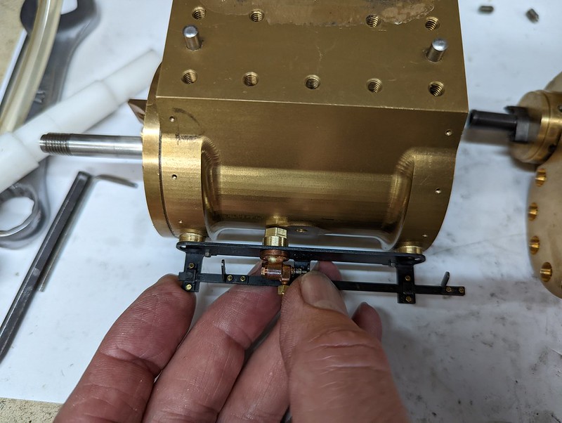 PXL_20220809_210234920 PXL_20220809_210234920 by Timothy Froud, on Flickr I forgot that I hadn't made the dummy M1.4 studs and bolts on the Drain Cock flange faces, so I need to address that. It's going to be fiddly. |
|
|
|
Post by doubletop on Aug 10, 2022 7:55:35 GMT
Roger It occurred to me that the Midland Show is a couple of months away and you must be pretty close to finishing your Speedy. Do you have any plans to let everybody see it in person and marvel at your efforts? I ask this because in the 14 months between now and the 2023 show you will have no doubt steamed it. After that it will never look as good as it did prior to the first steaming. Sadly, I wouldn’t get to see it myself as I’m unlikely to make it, despite having managed something like 4 of the last 6 shows. Pete Hi Pete, I certainly will show it at some point. I'm really bad at estimating how long jobs take though. I've still got the Pressure Gauges to make and some more Cab Fittings and details around the Pannier Tanks before those things can be painted. There's more to do on the whistle valves and some other bits and pieces on the backhead. I'm starting to get back into it now though after being too busy to get anything done. Hopefully one of our Foster Dogs finds his Forever Home tomorrow, and that will reduce the amount of dog walking I need to do. So whether it will be this next year or the following one is anyone's guess. It does finally feel like I'm approaching the home straight. I'm not going to be too precious about how it looks, nothing stays new for long. Roger You could still show it in its current state, I've seen Bob's Evening Star on more than one occasion as he progresses with his build. Pete |
|
|
|
Post by Roger on Aug 10, 2022 8:37:06 GMT
Hi Pete, I certainly will show it at some point. I'm really bad at estimating how long jobs take though. I've still got the Pressure Gauges to make and some more Cab Fittings and details around the Pannier Tanks before those things can be painted. There's more to do on the whistle valves and some other bits and pieces on the backhead. I'm starting to get back into it now though after being too busy to get anything done. Hopefully one of our Foster Dogs finds his Forever Home tomorrow, and that will reduce the amount of dog walking I need to do. So whether it will be this next year or the following one is anyone's guess. It does finally feel like I'm approaching the home straight. I'm not going to be too precious about how it looks, nothing stays new for long. Roger You could still show it in its current state, I've seen Bob's Evening Star on more than one occasion as he progresses with his build. Pete True, but it takes time out that would be better spent finishing it off. |
|
|
|
Post by Roger on Aug 12, 2022 21:48:43 GMT
I don't know if anyone bothers putting insulation under the Cladding, but there's room for it, and it may as well have some. 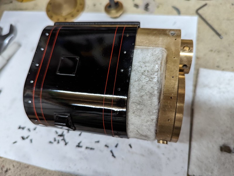 PXL_20220812_161535723 PXL_20220812_161535723 by Timothy Froud, on Flickr I found that I couldn't assemble the Cladding because the wrapper wouldn't spring enough to let the heads of the M1 bolts ride up over the lips and drop into the pockets machined for them. Rather than force it over, I used the Dremel and a small grinding wheel to remove the lip of the pocket and provide a route for the heads to slide into them.  PXL_20220812_163735399 PXL_20220812_163735399 by Timothy Froud, on Flickr  PXL_20220812_163759281 PXL_20220812_163759281 by Timothy Froud, on Flickr Anyway, other than that, they fit like a glove, so I'm happy. The bolts are barely finger tight, they don't have to do much and I don't want to damage the paint. I've rounded off the back of the hex on each of the 40 bolts, but there's no need to do them up tight. Putting the cylinder on does expose an issue with setting up the valves. Basically, you can't do that with the front Cladding in place, and you can't get it on or off with the cylinders in place. It's unfortunate, but that's the price you pay for a near Scale appearance. In reality, it's not so terrible. It just means that the valves will have to be set with the covers off, and the Cylinders will have to be removed so that the covers can be fitted. Since the adjustment isn't affected by removing any pins or parts of the valve gear, this can be done without any issues. Once it's been set accurately, it shouldn't need doing again. I'm going to need to add all of this to the assembly/disassembly procedure.  PXL_20220812_210339005 PXL_20220812_210339005 by Timothy Froud, on Flickr I couldn't resist seeing how this looks with the Steam Pipe cover and dummy Snifting Valve. I'm really pleased with that. 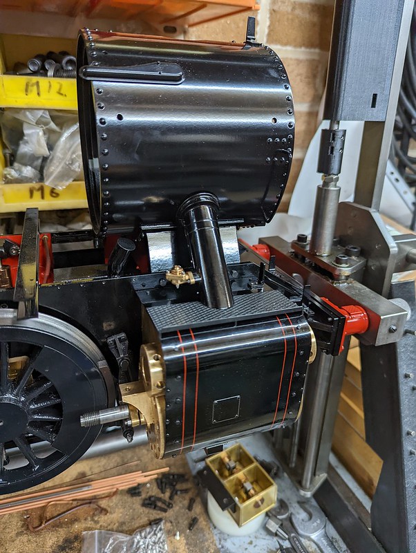 PXL_20220812_210543160 PXL_20220812_210543160 by Timothy Froud, on Flickr Next up is to assemble the Piston Valve Guide arrangement, complete with oil boxes. Again, the cladding can't go on after this is assembled on the chassis, so that needs to go on first. I'm really enjoying this phase of the project. It's so nice to have all of the pieces pretty much finished and ready to go on. |
|
|
|
Post by ettingtonliam on Aug 13, 2022 5:34:10 GMT
I don't know if anyone bothers putting insulation under the Cladding, but there's room for it, and it may as well have some. N Yes, in the far off prehistoric days of the 1960s, I lagged the cylinders of my first locomotive, a 3 1/2" Juliet. We had some pieces of asbestos cement sheet which I attacked with a large coarse file to produce a heap of asbestos cement dust, which I then wetted to form a paste, and duly lagged the cylinders. All I can say is that back then, I didn't know any better. No protective masks or gloves of course. I have no idea if the insulation made for a better running locomotive or not. |
|
|
|
Post by Roger on Aug 13, 2022 6:56:28 GMT
I don't know if anyone bothers putting insulation under the Cladding, but there's room for it, and it may as well have some. N Yes, in the far off prehistoric days of the 1960s, I lagged the cylinders of my first locomotive, a 3 1/2" Juliet. We had some pieces of asbestos cement sheet which I attacked with a large coarse file to produce a heap of asbestos cement dust, which I then wetted to form a paste, and duly lagged the cylinders. All I can say is that back then, I didn't know any better. No protective masks or gloves of course. I have no idea if the insulation made for a better running locomotive or not. It's frightening all of the things that were done in all innocence, later to discover there were appalling health risks. My Dad build his garage using a frame covered with corrogated Asbestos sheeting, all cut and drilled without masks. You can imagine how cold that was in the Winter, with zero insulation and draught proofing! To be honest, I don't think the insulation will make a noticeable difference, but it can't do any harm either. For the sake of 5 minutes work, it seemed worth doing. |
|
|
|
Post by simplyloco on Aug 13, 2022 7:56:47 GMT
SNIP We had some pieces of asbestos cement sheet which I attacked with a large coarse file to produce a heap of asbestos cement dust, which I then wetted to form a paste, and duly lagged the cylinders. All I can say is that back then, I didn't know any better. No protective masks or gloves of course. SNIP It's frightening all of the things that were done in all innocence, later to discover there were appalling health risks. SNIP Asbestos removal has been a gravy train for many years. My neighbour is having new windows fitted. Just like ours, the house has some white asbestos sheets under the eaves. She has been conned into paying for a specialist removal company to remove it before installation of the windows! We had new windows last year: not a mention of asbestos removal... |
|
|
|
Post by ettingtonliam on Aug 13, 2022 11:55:19 GMT
Doubtless I was releasing fibres into the air when I was vigouressly filing away in Dads garage. Anybody know which type of asbestos was used to make asbestos cement sheets?
|
|
|
|
Post by simplyloco on Aug 13, 2022 12:05:59 GMT
Doubtless I was releasing fibres into the air when I was vigouressly filing away in Dads garage. Anybody know which type of asbestos was used to make asbestos cement sheets? AFAIK ‘white asbestos’ (chrysotile) is normally in the sheets. From the H&SE website Some ACMs are more vulnerable to damage and more likely to give off fibres than others. In general, materials that contain a high percentage of asbestos are more easily damaged. The table above is roughly in order of ease of fibre release (with the highest potential fibre release first). Sprayed coatings, lagging and insulating board are more likely to contain blue or brown asbestos. Asbestos insulation and lagging can contain up to 85% asbestos and are most likely to give off fibres. Work with AIB can result in equally high fibre release if power tools are used. On the other hand, asbestos cement contains only 10–15%
asbestos. The asbestos is tightly bound into the cement and the material will only give off
fibres if it is badly damaged or broken, or is worked on (eg drilled, cut etc). |
|
|
|
Post by ettingtonliam on Aug 13, 2022 14:29:20 GMT
Asbestos cement was a popular material for water main pipes back in the day, too. I've seen that cut dry with a Stihl saw, big clouds of dust.
|
|
|
|
Post by Roger on Aug 13, 2022 21:38:42 GMT
It's been too hot to do much today, but I did manage to assemble most of the Valve Crosshead parts. This one is missing the far pipe which needs to go to the Expansion Link bearing on the Gear Frame. I'll make that when this is fitted. The oilers are all functional. There's no wick, just thick oil to control the flow.  PXL_20220813_212529406 PXL_20220813_212529406 by Timothy Froud, on Flickr You can see the oil pipe to the top of the Gland boss behind the Valve rod. I can't lock the forked piece in place yet because the Combination Lever has to be fitted first with its floating pin. The body of the Crosshead is made from Silicon Bronze because it has a much higher Youngs Modulus than Leaded Bronze that I tried first. That was way too springy. The wavy part is made from Gauge Plate, while the Fork is made from hardened Silver Steel. The gland cover is actually just a retainer for the Viton 'O' ring.  PXL_20220813_212609310 PXL_20220813_212609310 by Timothy Froud, on Flickr |
|
|
|
Post by chris vine on Aug 14, 2022 8:16:47 GMT
Hi Roger,
From experience with oil pipes going into piston/valve rod glands, I have a tiny modification for you:
On Bongo, I found that the pipe taking oil to the piston rod gland would regularly block up solid, so no oil could flow.
Taking it apart, I discovered that gunk from the graphite packing had been forced up the pipe. I don't know how this could happen, but it just does!
If you are using graphite packing (maybe you are using a split O ring?), then I would suggest that if you can arrange the pipe to just drop the oil into the hole in the gland, then that will be a better, working, solution than the neat version where the pipe sits in the hole.
On Bongo's pipe, it was so firmly blocked that even 100 psi on the air line would not budge the stuff!!
Chris.
|
|
|
|
Post by Roger on Aug 14, 2022 8:47:41 GMT
Hi Roger, From experience with oil pipes going into piston/valve rod glands, I have a tiny modification for you: On Bongo, I found that the pipe taking oil to the piston rod gland would regularly block up solid, so no oil could flow. Taking it apart, I discovered that gunk from the graphite packing had been forced up the pipe. I don't know how this could happen, but it just does! If you are using graphite packing (maybe you are using a split O ring?), then I would suggest that if you can arrange the pipe to just drop the oil into the hole in the gland, then that will be a better, working, solution than the neat version where the pipe sits in the hole. On Bongo's pipe, it was so firmly blocked that even 100 psi on the air line would not budge the stuff!! Chris. Hi Chris, Thanks for the heads up on that, it's not something I'd given any thought to. I'm using a Viton 'O' ring there, so I'm not sure how much material will come off that. Since they do eventually wear out, there must be something. There's no need to split the 'O' ring, it goes on over the end of the rod. |
|
JonL
Elder Statesman
WWSME (Wiltshire)
Posts: 2,911
|
Post by JonL on Aug 14, 2022 10:59:53 GMT
I'm amazed at how little wear there is on my Piston rings since installation (Silicone I think). They still seal beautifully after easily 100 miles.
|
|


