|
|
Post by Roger on Aug 15, 2022 7:02:34 GMT
I had to make four new longer studs for the Piston Rod Gland because they now have to retain the oiler box as well. I'm making these from 2.5mm Stainless Steel rod. Threading one end is easy, but holding the short cut off piece tightly enough to be able to run a die down it needs a lot of grip on a very short parallel length. Using a 3-jaw can leave marks, or it can slip. An ER collet will compress at the back, damage the thread and still not grip enough at the front.  PXL_20220814_105217453 PXL_20220814_105217453 by Timothy Froud, on Flickr Excuse the awful photo, I don't know what happened there. Anyway, can see the solution is to make a bung that goes in the back of the collet to support the rear so that the front can bite down on the part. The 'O' ring on the reduced diameter is just to stop it falling out. There's a short section just after the shoulder that is the only part that touches the collet. Simple but effective. I make these to suit each collet as necessary.  PXL_20220814_105511709 PXL_20220814_105511709 by Timothy Froud, on Flickr There's no positive angular registration for the Valve Crosshead, so I'm setting this on the surface table. You can see the black Oil Box on the piston shaft in this view.  PXL_20220814_145013676 PXL_20220814_145013676 by Timothy Froud, on Flickr The Piston Rod Gland uses a simple idea to allow me to use PTFE as the sealing material. An O-ring is going to have a hard time in this position, and I really didn't want to resort to ancient tech for this. The seal is just a scrap of PTFE that's a snug fit on the shaft. The two O-rings seal between the sleeve and the pocket in the Cylinder Cover, and also provide the spring force that keeps the PTFE in contact with the shaft. The whole thing is retained by the dummy gland which is designed to tighten to a mechanical stop, leaving just enough room for the seal with a little end clearance. It only took a few minutes to make, and ought to last a long time. We'll see.  Simplified piston rod gland Simplified piston rod gland by Timothy Froud, on Flickr  Piston rod gland assembly Piston rod gland assembly by Timothy Froud, on Flickr |
|
|
|
Post by Roger on Aug 15, 2022 20:26:18 GMT
Herre's how the Cylinders look on 1501, and you can see that the glands are black, as are the cast features of the Cylinder covers that you can see. I'd forgotten that these needed to be painted, so I'll have to do them before I can go any further.  20140204_112524 20140204_112524 by Timothy Froud, on Flickr So here's another forest of Spraying Mounts to hold the Cylinder rear covers, Piston rod glands and Piston Valve glands ready from spraying. 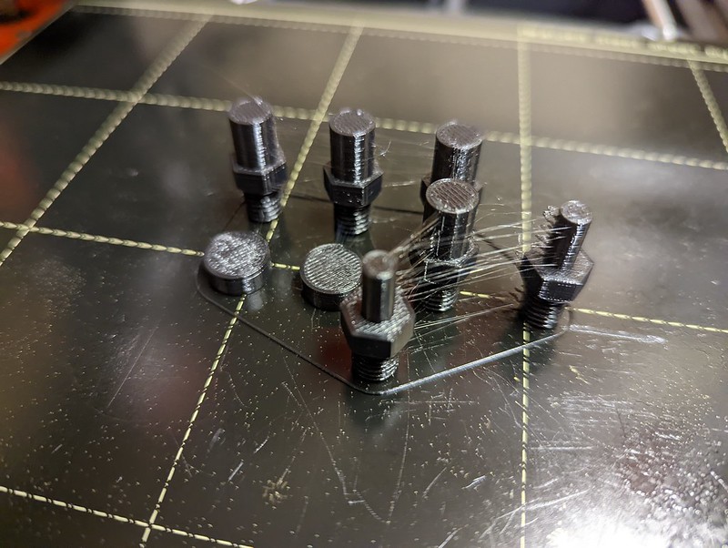 PXL_20220815_200337394 PXL_20220815_200337394 by Timothy Froud, on Flickr You can see that parts that are still Bronze colour and in need of painting. I was standing these on various pieces of packing, and decided that it would be worthwhile 3D printing a stand for them for when they're being assembled or serviced. The LH cylinder is sitting on one of them. It still has the Oil feed fitting attached, hence the need for the stand to be 15mm thick. I've extended the foot to include the overhang of the cylinder bottom so that it's more stable. The modelling took about 15 minutes while I figured out what features I wanted it to have, and the two of them took 5 hours to print in PETG, my goto filament. The two dowels are a close fit in the stand, making it really stable. I've also cut the M1.4 cover screws for the rear cylinder cover to length and Blacked them. There are two below the piston rod, and one above.  PXL_20220815_200653104 PXL_20220815_200653104 by Timothy Froud, on Flickr |
|
|
|
Post by Roger on Aug 23, 2022 21:27:55 GMT
I'm sure many of you will be thinking that you could just slap on a coat with a paint brush, and that would be plenty good enough, and you'd be right. However, it's dead easy to go the extra mile and treat these like all of the other parts. Shot blasting gives a really good key, and a combination of little 3D printed parts, heatshrink tubing and masking tape bung up all of the holes I need to keep clear. Of course, it also makes it dead easy to get a nice even thin coat by turning it around while spraying. So here they are after shot blasting...  PXL_20220823_100246742 PXL_20220823_100246742 by Timothy Froud, on Flickr ... after blowing off with an Air Gun and using Masking tape to pull off any dust or remaining grit.  PXL_20220823_104959233 PXL_20220823_104959233 by Timothy Froud, on Flickr Then it's the usual drill of spraying, waiting a couple of minutes...  PXL_20220823_130437001 PXL_20220823_130437001 by Timothy Froud, on Flickr ... putting the part on the block to dry and mounting the next one.  PXL_20220823_130609042 PXL_20220823_130609042 by Timothy Froud, on Flickr As usual, the preparation takes much more time than the spraying, but it's a very satisfying process. |
|
|
|
Post by chris vine on Aug 23, 2022 23:31:41 GMT
Hi Roger, for nuts bolts and other silly bits I made a stupidly simple tool.
It was a small tin with a large hole in the lid which fitted the nose of the blast gun. The base of the tin had hundreds of 1mm holes.
To use; fill tin with assorted nuts washers screws etc, fit lid and place in blast cabinet, hold gun firmly in top and shake hard while pulling trigger. Hundreds of silly bits surface treated in seconds!
Chris 🚂🚂
|
|
Gary L
Elder Statesman

Posts: 1,208
|
Post by Gary L on Aug 23, 2022 23:54:41 GMT
[Snip] The Piston Rod Gland uses a simple idea to allow me to use PTFE as the sealing material. An O-ring is going to have a hard time in this position, and I really didn't want to resort to ancient tech for this. The seal is just a scrap of PTFE that's a snug fit on the shaft. The two O-rings seal between the sleeve and the pocket in the Cylinder Cover, and also provide the spring force that keeps the PTFE in contact with the shaft. The whole thing is retained by the dummy gland which is designed to tighten to a mechanical stop, leaving just enough room for the seal with a little end clearance. It only took a few minutes to make, and ought to last a long time. We'll see. Simplified piston rod gland by Timothy Froud, on Flickr Piston rod gland assembly by Timothy Froud, on Flickr A bit late maybe, but other members might like to know that PTFE is available in the form of spun cord or braid. Thus you can get the benefit of old and new technology at the same time! The 'old' shouldn't be dismissed out of hand- the big benefit of using corded packings rather than O-rings for piston rods is that they can be replaced without removing the crosshead. PTFE makes it easy to make 'rings' by the correct method. I think users of graphited string tend to just wind it around the shaft until they have enough turns; the nature of the string means it is very hard to do it 'properly' whereas PTFE cord is much more amenable. The 'correct' way, for those that don't know, is to wind a length of cord or braid several times around a rod of the same dia as the shaft to be sealed. Secure both ends, then take a razor blade and make a single cut along the length of the shaft. Result: lots of accurate rings, which you feed into the stuffing box one by one, overlapping the joints, until you have nearly filled the box, then tighten the gland to taste. With PTFE take care not to overtighten; it has no 'spring', so it won't relax if you need to slacken it. (Apologies if teaching granny to suck eggs) I do recommend this as a perfect synthesis of the best of the old and the new. As an aside, I have done this with the glands on (full-size) gate valves for years. The default packing is a graphite collar, but graphite is electrolytic and corrodes the brass or bronze valve stem eventually. Replacing with PTFE braid has proved the perfect cure. Gary |
|
|
|
Post by Roger on Aug 24, 2022 6:21:40 GMT
Hi Roger, for nuts bolts and other silly bits I made a stupidly simple tool. It was a small tin with a large hole in the lid which fitted the nose of the blast gun. The base of the tin had hundreds of 1mm holes. To use; fill tin with assorted nuts washers screws etc, fit lid and place in blast cabinet, hold gun firmly in top and shake hard while pulling trigger. Hundreds of silly bits surface treated in seconds! Chris 🚂🚂 Hi Chris, What a brilliant idea! I've always thought that small parts would be a pain because they could fall through the grid in the cabinet and be really hard to retrieve. That's a fantastic solution. |
|
|
|
Post by Roger on Aug 24, 2022 6:32:53 GMT
[Snip] The Piston Rod Gland uses a simple idea to allow me to use PTFE as the sealing material. An O-ring is going to have a hard time in this position, and I really didn't want to resort to ancient tech for this. The seal is just a scrap of PTFE that's a snug fit on the shaft. The two O-rings seal between the sleeve and the pocket in the Cylinder Cover, and also provide the spring force that keeps the PTFE in contact with the shaft. The whole thing is retained by the dummy gland which is designed to tighten to a mechanical stop, leaving just enough room for the seal with a little end clearance. It only took a few minutes to make, and ought to last a long time. We'll see. Simplified piston rod gland by Timothy Froud, on Flickr Piston rod gland assembly by Timothy Froud, on Flickr A bit late maybe, but other members might like to know that PTFE is available in the form of spun cord or braid. Thus you can get the benefit of old and new technology at the same time! The 'old' shouldn't be dismissed out of hand- the big benefit of using corded packings rather than O-rings for piston rods is that they can be replaced without removing the crosshead. PTFE makes it easy to make 'rings' by the correct method. I think users of graphited string tend to just wind it around the shaft until they have enough turns; the nature of the string means it is very hard to do it 'properly' whereas PTFE cord is much more amenable. The 'correct' way, for those that don't know, is to wind a length of cord or braid several times around a rod of the same dia as the shaft to be sealed. Secure both ends, then take a razor blade and make a single cut along the length of the shaft. Result: lots of accurate rings, which you feed into the stuffing box one by one, overlapping the joints, until you have nearly filled the box, then tighten the gland to taste. With PTFE take care not to overtighten; it has no 'spring', so it won't relax if you need to slacken it. (Apologies if teaching granny to suck eggs) I do recommend this as a perfect synthesis of the best of the old and the new. As an aside, I have done this with the glands on (full-size) gate valves for years. The default packing is a graphite collar, but graphite is electrolytic and corrodes the brass or bronze valve stem eventually. Replacing with PTFE braid has proved the perfect cure. Gary Hi Gary, Those are good points. My objection to the traditional gland is about needing to adjust it over time to keep it sealed. I prefer a solution that adjusts itself. I've used 'O' rings on all of my valves for the same reason. I'll be able to remove the piston complete with rod while it's on the locomotive, so replacing the seal should be easy enough. I don't dismiss anything out of hand, it's about getting the best fit for the purpose, whether that's an old or a new idea. |
|
|
|
Post by Roger on Aug 24, 2022 17:34:19 GMT
Here are those parts sprayed today. I'm getting adept at mixing up tiny amounts of paint, this barely covered the bottom of the Spray Gun reservoir.  PXL_20220824_145318426 PXL_20220824_145318426 by Timothy Froud, on Flickr There was enough left to spray the underside of the cover plate that's between the frames at the front and gives access to the Lubricator.  PXL_20220824_145304202 PXL_20220824_145304202 by Timothy Froud, on Flickr |
|
|
|
Post by Roger on Aug 29, 2022 22:19:11 GMT
Here's the Cylinder back on with the Cylinder Cover painted Black. That looks much better.  PXL_20220829_220438389 PXL_20220829_220438389 by Timothy Froud, on Flickr However, getting the Front Cylinder Cover off wasn't easy, so I've decided to add a couple of jacking screws to that as shown below. 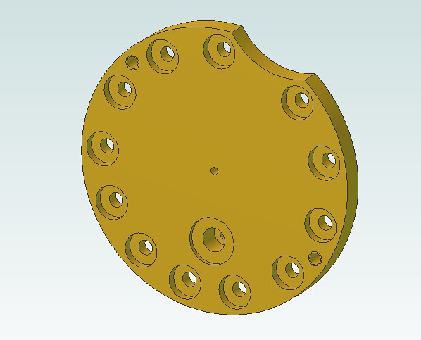 Cylinder front cover with jacking screws Cylinder front cover with jacking screws by Timothy Froud, on Flickr The same thing goes for this front cover, and I'm also going to have to add a clearance of some sort to get the Cladding on.  Front cover with clearance and jacking screws Front cover with clearance and jacking screws by Timothy Froud, on Flickr Here you can see what the issue is. If I could slide it straight on, it wouldn't be a problem. However, the hand rail gets in the way. It looks like removing some meat from the Piston Valve Sleeve, and the inside of the Cladding, might be sufficient to get this on without removing the Cylinder. i'd like to avoid that if at all possible so that I can set the valves with the Cylinder in place. Currently, the front cladding is designed in one piece, and I suppose I could make it differently. I'll try this first, I think I'll get away with it.  PXL_20220829_220507756 PXL_20220829_220507756 by Timothy Froud, on Flickr |
|
|
|
Post by Roger on Aug 31, 2022 19:27:30 GMT
Not being able to fit or remove the front Cylinder Cladding without removing the Cylinder from the frame would be a pain, so I put together a 3D model of the offending parts and it appeared that with a bit of work they could be made to fit. Here's the first side getting a generous clearance added to the corners of the Piston Valve Sleeve with the Dremel and a grinding point. Not ideal, but it gets the job done. 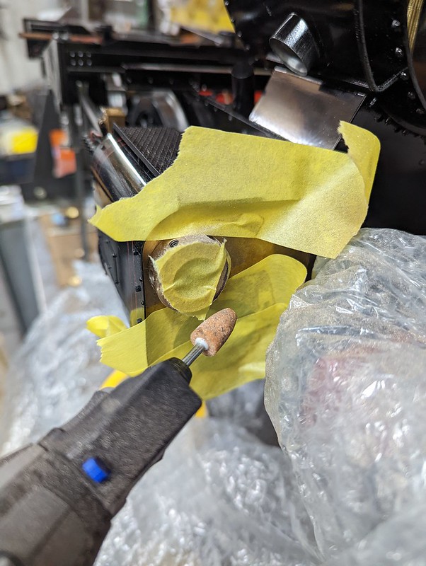 PXL_20220830_191935198 PXL_20220830_191935198 by Timothy Froud, on Flickr The inside of the Cladding needed similar treatment. Between the two there's enough play to just get it on.  PXL_20220831_191641793 PXL_20220831_191641793 by Timothy Froud, on Flickr There's still a clearance needed on the Piston Valve cover which I'll do shortly.  PXL_20220831_191507208 PXL_20220831_191507208 by Timothy Froud, on Flickr Mush as I don't like doing things like this, it's the least worse option. I need the Locomotive to be serviceable. This way I can release the dummy front oiler and Piston Valve Cosmetic sleeve and pull that out. Then it's just one bolt in the middle of the Cylinder Cover and all of this comes off. |
|
JonL
Elder Statesman
WWSME (Wiltshire)
Posts: 2,907
|
Post by JonL on Aug 31, 2022 20:27:35 GMT
I've had to relieve things in a similar way for the same reasons. It's cosmetically hidden and will improve your ability to service it; to me thats a win.
|
|
|
|
Post by Roger on Sept 3, 2022 21:56:27 GMT
Having had to strip the Cylinders and Valve gear from the Chassis a couple of times, it became clear that life would be a lot easier if there were jacking screws on the Cylinder Covers. So here some M3 tapped holes going into them as far out as practical. Sure, I could have just done them by hand, but I'd much rather put them in exactly as on the drawing. Here I've wedged a small piece of HSS with a tapered parting blade against two 3.1mm drill shanks to give something to clock to. I'm using the 4th axis because I can jog that through tiny angles quickly and easily to get it true.  PXL_20220903_085806004 PXL_20220903_085806004 by Timothy Froud, on Flickr I didn't clock the part centrally to the chuck, but just clocked the spindle to the flange.  PXL_20220903_091001673 PXL_20220903_091001673 by Timothy Froud, on Flickr Here's a similar thing being done for the Front Piston Valve Covers, as well as a generous clearance so I can get the Cladding on and off.  PXL_20220903_124651397 PXL_20220903_124651397 by Timothy Froud, on Flickr This is how that looks.  PXL_20220903_125411072 PXL_20220903_125411072 by Timothy Froud, on Flickr Here are the jacking screw points on the Rear Piston Covers. These aren't so difficult to get off because you've got something to grab hold of. However, it's even easier with jacking screws. 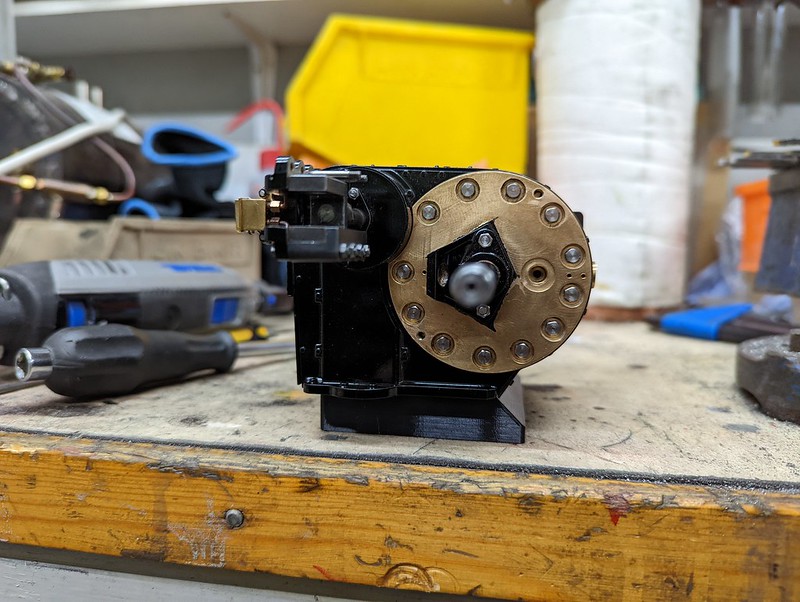 PXL_20220903_203113274 PXL_20220903_203113274 by Timothy Froud, on Flickr Disconnecting the Valve Gear from the Piston Valve Crosshead was a pain too. The easiest way to do this is to drop the outside bottom Crosshead Guide piece to gain access to the pins. However, getting them out was also a pain. The solution was to drill and tap the pins M3 so they can be pulled out with a screw being attached to them.  PXL_20220903_213351413 PXL_20220903_213351413 by Timothy Froud, on Flickr All of these things take time, but I'm determined not to make something that's a nightmare to work on. I'm gradually writing a procedure for the assembly and disassembly both for my convenience and for any future victim of my decisions. |
|
|
|
Post by Roger on Sept 6, 2022 21:26:03 GMT
There are quite a few Castle Nuts on the Valve Gear that need split pins, so here's one of the pins being drilled for that. I'm using a 0.85mm Carbide PCB drill which is very gingerly touched onto the thread, giving it time to cut and centre before drilling through.  PXL_20220906_194406793 PXL_20220906_194406793 by Timothy Froud, on Flickr I've done two of these tonight, with another eight still to do. There's no point in rushing this sort of thing, it can all go horribly wrong rather quickly.  PXL_20220906_211640968 PXL_20220906_211640968 by Timothy Froud, on Flickr |
|
|
|
Post by Roger on Sept 8, 2022 8:42:43 GMT
I ended up making three Aluminium split collets to hold the various pins that needed holes cross drilled for Split Pins. The drill chuck privided a handy way to hold these parts, providing enough clearance for the cutter to miss the body. I clocked the Spindle to be on the centre of rotation of the 4th Axis so that all I needed to do was to get the parts to run true and probe the end to get them centralised. Each one needed a small adjustment of the 4-jaw to get it right, but that didn't take long. It's better to take a bit of time and get it dead right rather than have to make it all again.  PXL_20220907_143537621 PXL_20220907_143537621 by Timothy Froud, on Flickr  PXL_20220907_144638229 PXL_20220907_144638229 by Timothy Froud, on Flickr I also noticed that I'd forgotten to drill the oil hole through the hardened bush in the Eccentric Rods, so that's being done here. I've left enough of the boss showing to be able to use the Edge Finder on all four sides to find the middle. The bush is so hard that it was really hard to drill, even with a Carbide PCB drill. The amount of force required was quite remarkable, and it was a wonder that I only broke one drill on the second rod. I used a diamond needle file on the inside to break the edge so it wouldn't shave the bearing shaft.  PXL_20220907_213321621 PXL_20220907_213321621 by Timothy Froud, on Flickr Anyway, this side is almost finished. I just need to fit the top of the Crosshead and see if the shim I've used to get the Crosshed bar to the correct height is right. It's all very close fitting, but it still turns nicely, albeit a little stiff overall. I'll give it a good run on air when it's all together to loosen it up a bit. 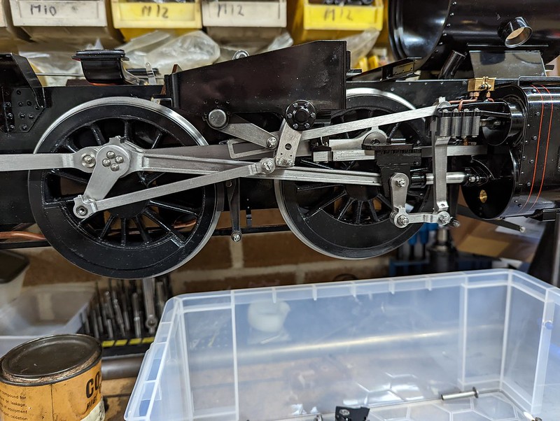 PXL_20220907_220355385 PXL_20220907_220355385 by Timothy Froud, on Flickr |
|
|
|
Post by Roger on Sept 9, 2022 21:06:01 GMT
Tightening up the Crosshead bolts made everything solid, so that had to come off again. It turns out that I'd swapped the LH and RH Crosshed Guide Bars and they are very slightly different thicknesses. The clearances are very small, so it was enough to be a problem. Anyway, here it is back together, and I'm using Slip Gauges to measure the distance between the Piston Rod and the bottom of the Crosshead Guide Bar. I'd put the shim back at the front that came off from the original assembly, but that's not right. Taking it out makes it just about right, so this side isn't geting a shim. It wasn't designed to have one, so this looks right now. I don't think I used Slip Gauges last time I put this together as a running chassis, so maybe it was wrong then too. Who knows. It's all pretty tight, so it's going to take a fair bit of running in.  PXL_20220909_203219218 PXL_20220909_203219218 by Timothy Froud, on Flickr  PXL_20220909_203408132 PXL_20220909_203408132 by Timothy Froud, on Flickr At least I can now move on to the other side. |
|
|
|
Post by Roger on Sept 14, 2022 21:40:18 GMT
The Relief Valves on the Cylinders need finishing now I've decided to make them functional. I'd got as far as getting some Stainless Steel Spring wire for them, but hadn't got round to experimenting with the spring sizes and weight. This is what I finally ended up with, 1mm wire with 1.5mm pitch and 4.8mm OD. Sorry about the blurry picture, but you get the idea. The adjuster is M2 and that needs a 0.5mm slot across the end. I'll do those when they are all working.  PXL_20220914_205714431 PXL_20220914_205714431 by Timothy Froud, on Flickr Anyway, this is the setup for winding the springs. The wire is pretty tough, so a stout setup is needed. I'm using my wire guide with the hole through it in the toolpost. The screw cutting pitch was set to 1.5mm and bottom RPM  PXL_20220913_194836558 PXL_20220913_194836558 by Timothy Froud, on Flickr About 20mm of the wire was fitted between the chuck jaws, and by chance that nipped nicely as the chuck was tightened onto the 2.5mm Silver Steel mandrel.  PXL_20220913_194826256 PXL_20220913_194826256 by Timothy Froud, on Flickr The end was supported by a short piece of Brass in the Tailstock which had a 2.5mm hole drilled through it.  PXL_20220913_194936921 PXL_20220913_194936921 by Timothy Froud, on Flickr A cutting disk in the Dremel was used to cut the springs to length. The spring was supported on the 2.5mm Silver Steel. I made a short mandrel which was the length of the Spring (5mm) and each was placed both was round to bring it to the finished size. I've got a plunger type 1micron resolution DTI on the table, so I set that to zero when touching the end of the mandrel. The Springs have such a short pitch and large wire that I could get away without any special bending of the end coils. They just needed a touch with a Diamond needle file round off the sharp edges. 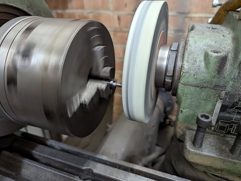 PXL_20220914_201818614 PXL_20220914_201818614 by Timothy Froud, on Flickr I did a trial run yesterday using the Hand Pump that was used for the boiler hydraulic test. The opening pressure seemed to be satisfactory, but the spring was slightly too long. Anyway, it was good enough to see that the pressure could be adjusted to be somewhere near the right ball park. |
|
|
|
Post by chris vine on Sept 14, 2022 23:00:24 GMT
Hi Roger,
I made the relief valve on Bongo functional.
Good thing I did too! Once, the loco primed just as the wheels slipped.
There was a funny noise, a bit of a knock and the relief valves lifted, just like they should.
That saved something getting bent...
Chris.
|
|
|
|
Post by Roger on Sept 15, 2022 6:38:22 GMT
Hi Roger, I made the relief valve on Bongo functional. Good thing I did too! Once, the loco primed just as the wheels slipped. There was a funny noise, a bit of a knock and the relief valves lifted, just like they should. That saved something getting bent... Chris. Hi Chris, That's good to know, I'm sure some people think it's a waste of time making them functional. I can certainly see how your situation could have bent something. |
|
|
|
Post by steamer5 on Sept 15, 2022 7:34:27 GMT
Hi Roger,
Chris’s comment brings back memories!
Youngest sone was driving my loco…. Under instruction, he had been doing a great job. Then the film crew turned up! Suitably sidetracked at the station with injector on…… you can see we’re this is going! By the time I spotted it the boiler must of been all but fill! Made sure the cylinder drains were open, gingerly opened the regulator…….. lovely fountain of hot water up the chimney, hot water out the drains! A slow trip, with fountain & cylinder drains slowly decreasing! Luckily no damage! Well to the loco! Pride some what damaged!
Cheers Kerrin
|
|
|
|
Post by Roger on Sept 15, 2022 12:05:00 GMT
Hi Roger, Chris’s comment brings back memories! Youngest sone was driving my loco…. Under instruction, he had been doing a great job. Then the film crew turned up! Suitably sidetracked at the station with injector on…… you can see we’re this is going! By the time I spotted it the boiler must of been all but fill! Made sure the cylinder drains were open, gingerly opened the regulator…….. lovely fountain of hot water up the chimney, hot water out the drains! A slow trip, with fountain & cylinder drains slowly decreasing! Luckily no damage! Well to the loco! Pride some what damaged! Cheers Kerrin Hi Kerrin, It's so easily done, I've forgotten to turn an injector off more than once. Fortunately it's not been enough to prime... yet! |
|


