|
|
Post by Shawki Shlemon on Oct 6, 2022 8:57:15 GMT
that is like a whistle valve .
|
|
|
|
Post by andyhigham on Oct 6, 2022 9:53:09 GMT
In your rendering, if you omitted the spring at the right hand side it would probably function as an automatic drain cock. the plunger could be used to override to open
|
|
|
|
Post by Roger on Oct 6, 2022 11:04:09 GMT
In your rendering, if you omitted the spring at the right hand side it would probably function as an automatic drain cock. the plunger could be used to override to open I haven't seen an automatic drain cock, but I imagine the ball is lightly sprung away from the seat? If you removed the RH spring, the steam would surely push the ball onto the seat? |
|
|
|
Post by andyhigham on Oct 6, 2022 11:23:13 GMT
Yes steam will push the ball onto the seat but if water is present the ball drops off the seat
|
|
uuu
Elder Statesman
 your message here...
Posts: 2,814
|
Post by uuu on Oct 6, 2022 11:25:16 GMT
A bit like injectors - they defy easy understanding.
Wilf
|
|
JonL
Elder Statesman
WWSME (Wiltshire)
Posts: 2,911
|
Post by JonL on Oct 7, 2022 15:28:55 GMT
Yes steam will push the ball onto the seat but if water is present the ball drops off the seat Thats how mine work. Quite efficient. The only annoyance is they get Mayo'd up every now and then and need a quick blast of brake cleaner. |
|
|
|
Post by Roger on Oct 7, 2022 22:19:49 GMT
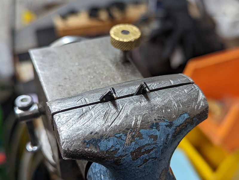
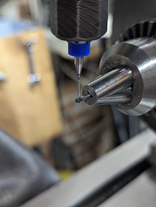
The triangular bracket in the middle of this actuating bar has a 1mm diameter pin attached to it which engages with the slot on a link. However, the pin has to reach a further 1.8mm from the face before reaching the slot, and I'm not happy with that much overhang when it's so slender. I think it's likely to either get bent or work loose in the bracket. 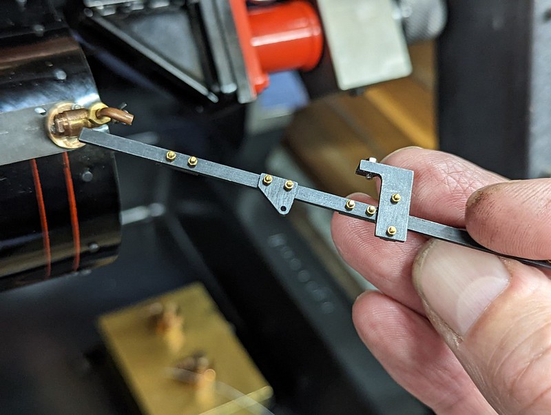 PXL_20221007_213010780 PXL_20221007_213010780 by Timothy Froud, on Flickr So I've decided to make those again, but this time with a boss to support the 1mm rod. I'll probably sacrifice a 1mm HSS drill for the pin, and just Loctite it in place.  PXL_20221007_212937643 PXL_20221007_212937643 by Timothy Froud, on Flickr The next thing I need to do is to add the drop link at the front of the long lever that comes from the cab. It's tucked between the bottom of the frame and the brake rod. I foolishly imagined that I'd easily fit that, but it's absolutely impossible to get to with the Cylinder in place. So here it is with all but one of the Cylinder bolts removed, the Lubricator taken off, the Valve gear disconnected and the Connecting rod detached.  PXL_20221007_215750199 PXL_20221007_215750199 by Timothy Froud, on Flickr The complete assembly comes off easily once the two bolts holding the crosshead have been removed. The whole thing came off in about half an hour. Here it is sitting on the 3D printed mount. The good thing about this arrangement is that you won't lose the valve timing if this has to come off.  PXL_20221007_220015843 PXL_20221007_220015843 by Timothy Froud, on Flickr And here's the offending drop link. It supports the front of the rod from the cab, and provides an anchor for a second link that goes to the cross shaft. All will be revealed shortly. 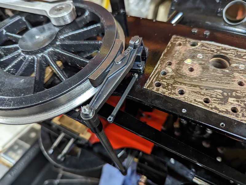 PXL_20221007_220529777 PXL_20221007_220529777 by Timothy Froud, on Flickr |
|
|
|
Post by Roger on Oct 8, 2022 21:42:36 GMT
|
|
|
|
Post by Roger on Oct 9, 2022 20:58:16 GMT
Continuing with the assembly of the Drain Cock mechanism, it would appear that I've folded the base plate in slightly the wrong position. With hindsight, I should have made a little fixture to guarantee it was right rather than use the folder. Anyway, rather than make new base plates which would risk running into other issues, I decided to make a modified bracket to correct the error in the position of the shaft and the clearance. So this plate was originally flat, but I've added a 0.5mm step for the clearance and moved the holes 0.3mm closer together.  PXL_20221009_200141112 PXL_20221009_200141112 by Timothy Froud, on Flickr The cross shaft now slides in nicely, and everything else looks like it fits properly now.  PXL_20221009_203955164 PXL_20221009_203955164 by Timothy Froud, on Flickr I think I'm probably going to just Loctite the tiny slotted lever to the rod. It's so small that trying to pin it is going to be next to impossible. Again, with hindsight I'd probably have made the boss big enough to pin it. I think it will be fine, but that's what I'll do if Loctite isn't strong enough.  PXL_20221009_204004449 PXL_20221009_204004449 by Timothy Froud, on Flickr |
|
|
|
Post by Roger on Oct 11, 2022 21:21:08 GMT
|
|
|
|
Post by Shawki Shlemon on Oct 13, 2022 8:07:55 GMT
Here is a drawing for auto drain cocks , they work as explained above .  |
|
stevep
Elder Statesman
Posts: 1,070
|
Post by stevep on Oct 13, 2022 9:01:41 GMT
I have never understood how 'auto drain cocks' work.
Surely, the intention of drain cocks is to allow steam into (and out) of the cylinders until they are warmed up, letting any condensed water out at the same time. When the driver is satisfied that everything is hot, they can close the cocks and carry on running.
With an auto cock, won't it close as soon as steam starts to blow through - before the cylinders are fully warm, and potentially, whilst there is still water in the cylinders? With piston valves, that could be catastrophic.
|
|
|
|
Post by Roger on Oct 13, 2022 10:28:09 GMT
Thanks for that Shawki.
I'd love to see a clear Acrylic one of these in action to see exactly what happens. Obviously there's a difference in the way that water flows in any environment compared to a gas, maybe something in that is being exploited? Perhaps the internal geometry tends to make the ball stay on the bottom or even roll to the right when it's filled with water?
Either way, it's a clever device, probably discovered by accident.
|
|
JonL
Elder Statesman
WWSME (Wiltshire)
Posts: 2,911
|
Post by JonL on Oct 13, 2022 17:40:21 GMT
I think its the turbulence of the water coming in at 90 degrees that unseats the valve. I wonder if they would still work if they were not at 90 degrees. They appear to be very effective.
|
|
|
|
Post by Roger on Oct 13, 2022 21:40:35 GMT
I'd very much like to get the Chassis running on Air again, but this time I want to have it sitting on its springs at the correct ride height. LBSC just says to use 18 gauge wire, with no indication of the length, so I've worked out the amount of room there is with the axle in the lowest position and run with that for a first attempt. Looking at various springs on the Polly Models site, I reckon the pitch needs to be about 2.5mm This is the setup, with a piece of 4mm Silver Steel supported by a bar with a reamed hole in the Tailstock. The wire is trapped between the Chuck Jaws using card and paper to get the right pinch. I've started it off with a single turn, then engaged the Half Nuts to wind the spring. I stop and wind it to 19mm and then disengage the feed, followed by another turn to close the end.  PXL_20221013_211330340 PXL_20221013_211330340 by Timothy Froud, on Flickr Here's what those look like. I'll grind the ends flat and aim for 20mm overall. The idea is to put the Boiler in place, and probably the Pannier Tanks too so that I'm close to the final weight. Then I'll put the springs on a single end of one axle and use spacers to set the other axleboxes to the correct height. The hope is that the axle can be set to the correct ride height while it's all sitting on the Weighbridge so I can get some indication as to whether the length and spring rating is anywhere near what's required. If it looks promising, I'll make the rest of them. There's no point in making twelve of them if they're miles out.  PXL_20221013_212438749 PXL_20221013_212438749 by Timothy Froud, on Flickr |
|
|
|
Post by chris vine on Oct 13, 2022 21:53:32 GMT
Hi Roger,
Those springs look lovely!
The important thing is that the springs push the wheels down to the bottom of their travel and are not too stiff.
That way the engine will compress them approx half way and the wheels will still be pushed down into track hollows.
As inspector clouseau said, “I know that you know this”!!
Chris
|
|
|
|
Post by Roger on Oct 14, 2022 6:37:20 GMT
Hi Roger, Those springs look lovely! The important thing is that the springs push the wheels down to the bottom of their travel and are not too stiff. That way the engine will compress them approx half way and the wheels will still be pushed down into track hollows. As inspector clouseau said, “I know that you know this”!! Chris Hi Chris, Thanks for that. It seems a simple thing to get right on the face of it, but not quite as simple when you look deeper. I imagine that you might have to make the springs longer if they were softer, then compress them to get the nuts on? The requirement is to get the ride height right, so I can't see another way of achieving soft springing without changing the spring length. Obviously there's a small amount of adjustment, but you don't want to have the nuts wound right up the studs. |
|
|
|
Post by chris vine on Oct 14, 2022 22:07:32 GMT
Hi Roger,
There is a very weird version of a spring formula which gives the resonant frequency of a mass on a spring: you need to enter g for your local gravity acceleration , but apart from that the natural frequency depends only on the length the spring has been compressed to support the mass. You don’t need to know the mass and I don’t think you even need to know the rate of the spring.
A bit counter intuitive.
Maybe I’ve got it wrong, I will try to find it when I am back at base…
Chris
|
|
44767
Statesman

Posts: 529
|
Post by 44767 on Oct 15, 2022 3:25:01 GMT
Hi Chris, Thanks for that. It seems a simple thing to get right on the face of it, but not quite as simple when you look deeper. I imagine that you might have to make the springs longer if they were softer, then compress them to get the nuts on? The requirement is to get the ride height right, so I can't see another way of achieving soft springing without changing the spring length. Obviously there's a small amount of adjustment, but you don't want to have the nuts wound right up the studs. Roger, More turns for the same length, smaller wire gauge or larger diameter coil will all result in a softer spring. You will need the springs to be longer and have some pre-load on them (break-off force) otherwise when the load is at the bottom, there will be no force actually pushing it there. Cheers,Mike |
|
|
|
Post by Roger on Oct 15, 2022 10:33:07 GMT
Hi Roger, There is a very weird version of a spring formula which gives the resonant frequency of a mass on a spring: you need to enter g for your local gravity acceleration , but apart from that the natural frequency depends only on the length the spring has been compressed to support the mass. You don’t need to know the mass and I don’t think you even need to know the rate of the spring. A bit counter intuitive. Maybe I’ve got it wrong, I will try to find it when I am back at base… Chris Hi Chris, That takes me back to my Engineering Degree when we had to do all that stuff. Simple Mass/Spring systems were easy enough, but it got a lot more complicated when there were gears and torsional stiffnesses to deal with. I don't think resonance is going to be an issue here, the dampers ought to deal with that. |
|