|
|
Post by Roger on Sept 28, 2022 20:53:11 GMT
Just a quick update on my attempt to dissolve the three Florist's Wires that are stuck in the sharp bend of the Oil pipe. NB:- Nitrile gloves and safety goggles were worn through all of the following processes! First, I forced some Alkali Degreaser through the pipe using the air line attached to the fitting. I could see it coming out the end, so I left it overnight to do its work. I then flushed it through with water and mixed up a small quantity of Alum, adding it to some near boiling water until it wouldn't dissolve any more. Some of this was put in the fitting with a syringe, and the air line was again used to force it through. However, I couldn't get anything out of the end when doing this. I've seen this issue before when trying to unblock the water jackets on High Speed Spindles. You could blow air through them... just... but when the Detartrol solution was introduced, nothing would come out. Sometimes if you left it long enough, it would eventually clear, but it was never a good sign. I think what happens is that the first part that the solution reached reacts to make a gas, and that stops more fluid reaching the things you want it to react with. We used a Peristaltic pump to push the fluid through, and maybe we should have used a much higher pressure pump. Anyway, this is the setup I've got, with the pipe and header almost submerged in the Ultrasonic Tank, with the timer set to max and the heater on 40C.  PXL_20220928_202342525 PXL_20220928_202342525 by Timothy Froud, on Flickr You can see it's foaming slightly, so maybe it is doing something. Personally I'm doubtful, but I'll let it stand overnight and see if I can force more through. I've put a sample of Florists Wire in the solution to see if it's going to get dissolved.  PXL_20220928_202328138 PXL_20220928_202328138 by Timothy Froud, on Flickr Here are two short Oil pipes that I've made for the drop test. The one on the right has roughly a 30 degree slope on the end and a parallel bore.  PXL_20220928_202029095 PXL_20220928_202029095 by Timothy Froud, on Flickr The one on the left has a 45 degree internal chamfer.  PXL_20220928_202037744 PXL_20220928_202037744 by Timothy Froud, on Flickr I've set it up using one of the Oil Boxes and that can sit overnight to see what happens. Place your bets now! Personally, my money is on the one on the left. 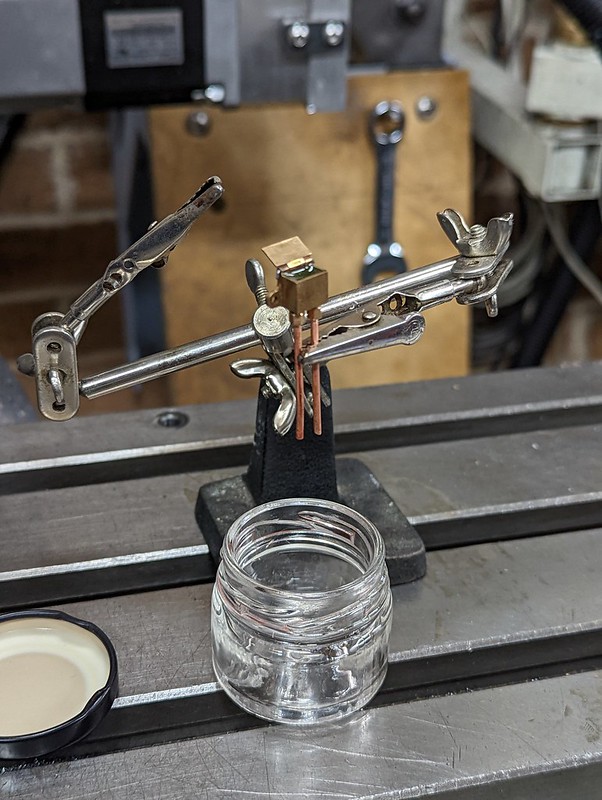 PXL_20220928_202231195 PXL_20220928_202231195 by Timothy Froud, on Flickr |
|
|
|
Post by chris vine on Sept 29, 2022 7:38:37 GMT
Hi Roger,
My bet is that there won't be much difference between the two!!
Chris.
|
|
|
|
Post by Roger on Sept 30, 2022 6:48:11 GMT
I'd have to perform more tests to make this meaningful, but they both allow oil to drop off the end, and that's what I really wanted to know. My concern was that if the pipe wasn't touchiing anything, it might not feed any oil. It takes ages to form a drop, so I didn't catch the one on the right. However, you can see that it's wet the outside of the tube like the LH one has, so I think this is going to be fine whatever I do.  PXL_20220929_200041566 PXL_20220929_200041566 by Timothy Froud, on Flickr I decided to just put a small chamfer on the inside with a spotting drill. The Alum failed to remove the Florist's Wire, and that's really no surprise. The wire I immersed in it didn't dissolve either, and that may be due to a coating on the wire. Anyway, enough messing about with that, I made another and that's now fitted to the Locomotive. All of the Oil Boxes have been filled and it will be interesting to see if they drain through given enough time. With hindsight it would have been better to have put a divider in the Oil Boxes so I could see if one of the pipes was blocked. It's too much hassle to do anything about that now though. |
|
|
|
Post by chris vine on Sept 30, 2022 7:29:35 GMT
Hi Roger,
Yes, I wish I had made dividers in my oil boxes.
Especially as the pipe which feeds oil to the piston rod gland used to block with bits and gunk from the graphite string.
To avoid this, I had to lift the pipe out of its carefully positioned hole in the gland and arrange it just to drip on the piston rod!
You won't have this problem as you are not using graphite string...
I terms of size of drop from end of pipe: I suspect the end shape doesn't make much difference, but the overall diameter of the pipe might do.
Chris.
|
|
|
|
Post by Roger on Sept 30, 2022 10:07:19 GMT
Hi Roger, Yes, I wish I had made dividers in my oil boxes. Especially as the pipe which feeds oil to the piston rod gland used to block with bits and gunk from the graphite string. To avoid this, I had to lift the pipe out of its carefully positioned hole in the gland and arrange it just to drip on the piston rod! You won't have this problem as you are not using graphite string... I terms of size of drop from end of pipe: I suspect the end shape doesn't make much difference, but the overall diameter of the pipe might do. Chris. Hi Chris, I'm wondering if a 3D printed divider might be an answer to this problem. I don't suppose it needs to be a perfect seal because surface tension would probably stop any flow if there's a tiny gap. I might have a go at that. I'm not sure about the size of the drop. I know that if you have an external chamfer coming to a sharp edge, you don't get a drop that will fall off. One issue might still remain, and that's the length of the pipe. Trying to force oil through the longest ones with the oil can was really hard compared to the short ones. That's not a surprise really. I have a feeling that it won't make much difference in practice though, because the flow rate is negligable. I find it all interesting though, I hadn't given any of this much thought until now. All I've done before is to size the Oil hole in the Axleboxes to get enough flow. My original holes were so small that nothing came through at all. |
|
|
|
Post by Cro on Sept 30, 2022 12:13:56 GMT
One thing to consider is heat, oil pots around the cylinders and close to the boiler will get warm and the oil will flow better - you could try warming the oil pot very gently and seeing if that makes a difference on your longer pipe?
|
|
|
|
Post by Roger on Sept 30, 2022 12:25:15 GMT
One thing to consider is heat, oil pots around the cylinders and close to the boiler will get warm and the oil will flow better - you could try warming the oil pot very gently and seeing if that makes a difference on your longer pipe? Good point, it's sure to make a difference when everything warms up. To be honest, none of it needs more than a smear of oil, so even the slightest flow it probably enough. |
|
|
|
Post by chris vine on Sept 30, 2022 13:31:05 GMT
I don't think a divider which doesn't have a good seal will work.
There is no surface tension unless there is a surface.
In your case, the divider will be in the oil so there is no surface to prevent flow. The oil will find its way through the gaps...
Chris.
|
|
|
|
Post by Roger on Sept 30, 2022 16:01:49 GMT
I don't think a divider which doesn't have a good seal will work. There is no surface tension unless there is a surface. In your case, the divider will be in the oil so there is no surface to prevent flow. The oil will find its way through the gaps... Chris. Ok, it will have to be a very close fit then. I'll leave it for the moment, it might be possible to see that they're both working on each one, at least initially. |
|
|
|
Post by steamer5 on Sept 30, 2022 17:27:10 GMT
Hey Roger,
Would it be possible to fit an o-ring around the 3d printed divider? Downside would be it would use up volume
Cheers Kerrin
|
|
|
|
Post by Roger on Sept 30, 2022 18:32:50 GMT
Hey Roger, Would it be possible to fit an o-ring around the 3d printed divider? Downside would be it would use up volume Cheers Kerrin That's certainly possible, or I suppose they could be just bonded in with a smear of Epoxy. Alternatively, I do have some compliant filament that could be designed to flex at the outside. I'm not overly concerned about losing a little volume. None of the places need to be swimming in oil, as long as they have a film it's fine. |
|
|
|
Post by Roger on Sept 30, 2022 21:03:18 GMT
Here's my thought on the Oil Box divider. It's 4mm x 6mm with a 1mm thick divider. The bottom cenres it against where the pipe fittings come through. There is a slight hollow in the face that presses against the vertical wall. The idea is to make it a push fit and for those edges to deform slightly.  Oil box divider Oil box divider by Timothy Froud, on Flickr Hopefully the Lubricator is finally on for good. Each time I've put it back on it's been a struggle because the M4 hex bolts drop down inside the socket. Enough is enough, I hate things being like that, so I've swapped them for Cap Screws which can easily be fitted with an Allen driver.  PXL_20220930_201347486 PXL_20220930_201347486 by Timothy Froud, on Flickr The Lubricator system is really simple because the oil is delivered onto the top of the Steam Chest through drill ways in the Cylinder body.  PXL_20220930_201334157 PXL_20220930_201334157 by Timothy Froud, on Flickr I just realised that I've still got to make the drain fitting for the Exhaust cavity. The plan is to add a fine Copper pipe to the Frame Plate so that any oil collecting in the Exhaust cavity in the back of the Cylinder can drain automatically. I'm imagining oil gradually filling the pocket and getting carried over in droplets to be worn by the driver. Originally I'd intended to put some coarse Stainless Steel pan scrubber in the cavity to help remove the oil from the exhaust. In the end, I decided against the idea, but I still think oil will collect there. With nowhere else to go, it's got to end up going up the Chimney. The other obvious things missing are the Drain Cocks. They've all been made, and there are just a couple of pieces to be sorted out for the actuating mechanism. |
|
|
|
Post by Roger on Oct 1, 2022 14:11:14 GMT
Here's one of the drain fittings for the Exhaust oil getting a 0.3mm metering hole in the back. The idea is to make sure that when there's just Exhaust Steam pressure in the pocket there's a very restricted path for it.  PXL_20221001_094102343 PXL_20221001_094102343 by Timothy Froud, on Flickr The drain is going to be taken towards the middle of the track so it doesn't go onto the rails. This is a piece of M2.5 thread 8mm long being drilled through at 1mm The end has a 30 degree chamfer for the swaged pipe fitting.  PXL_20221001_115220801 PXL_20221001_115220801 by Timothy Froud, on Flickr  PXL_20221001_134042752 PXL_20221001_134042752 by Timothy Froud, on Flickr This is how it looks on the Locomotive. Before anyone jumps in to say this is a solution to a non-existant problem, I would ask how you know that? In my mind, Steam containing oil passing through the passageways and up the Blast Pipe will deposit oil onto anything it comes into contact with. If this wasn't the case, the Oil wouldn't find its way onto the Cylinders either. All of the oil that's fed into the system has to come out somewhere in the end. Unless there are leaks, all of it must come out of the Chimney. Obviously, we want the minimum quantity of oil to be effective, but there must still be some being carried over into the exhaust. So, the idea is simply to give any oil, that gets as far as the Exhaust pockets in the Cylinders, the opportunity to exit somewhere other than the Blast pipe when the level is high enough. For all I know, it might take years for this to happen, but it pleases me to explore these ideas. Has anyone seen or done anything like this before?  PXL_20221001_135317055 PXL_20221001_135317055 by Timothy Froud, on Flickr |
|
|
|
Post by ettingtonliam on Oct 1, 2022 16:15:17 GMT
Going back to your attempts to dissolve the florists wire in the tube, and possible reasons why it didn't work. I tried it a couple of years ago, and purchased Alum off ebay, which turned out to be potassium sulphate, and it didn't work. Turns out I should have bought potassium aluminium sulphate, which I am assured will work. Both types are commonly known as 'alum'
PAS will dissolve steel in a non ferrous material such as brass, copper, aluminium etc. It won't dissolve steel in steel, or steel on its own.
All the accounts of the method I've read seem to use a glass or pot bowl, so I'm not sure if using your stainless steel container might have affected the results. I suppose plastic would be OK, but that wouldn't let you keep the liquid hot on top of the stove, would it?
In my case I ended up punching the tap out from the back, and retapping a larger size.
|
|
|
|
Post by Roger on Oct 1, 2022 18:09:54 GMT
Going back to your attempts to dissolve the florists wire in the tube, and possible reasons why it didn't work. I tried it a couple of years ago, and purchased Alum off ebay, which turned out to be potassium sulphate, and it didn't work. Turns out I should have bought potassium aluminium sulphate, which I am assured will work. Both types are commonly known as 'alum' PAS will dissolve steel in a non ferrous material such as brass, copper, aluminium etc. It won't dissolve steel in steel, or steel on its own. All the accounts of the method I've read seem to use a glass or pot bowl, so I'm not sure if using your stainless steel container might have affected the results. I suppose plastic would be OK, but that wouldn't let you keep the liquid hot on top of the stove, would it? In my case I ended up punching the tap out from the back, and retapping a larger size. Thanks for those thoughts. I've just checked, and the listing was for Aluminium Potassium Sulphate, also called Potash Alum there. I ought to try some on a scrap of clean Mild Steel to see if it works on that. I'm not sure what the reaction is, maybe there's a Chemist who can shed more light on it? |
|
|
|
Post by ettingtonliam on Oct 1, 2022 18:30:47 GMT
From what I read, it won't react with steel on its own, it needs to be steel in close contact with a non ferrous metal. Thats why it works with a tap or drill broken off in a bronze fitting. I suspect it won't work on carbide drills.
|
|
|
|
Post by chris vine on Oct 1, 2022 23:21:34 GMT
My Mum, who was a talented silver smith/jeweller, kept her alum in an enamel bowl.
Whether this was by design or accident I don't know. However, it was not in contact with the steel of the bowl. I guess that would have used up the Alum...
Chris.
|
|
|
|
Post by Roger on Oct 2, 2022 13:03:46 GMT
The Drain Cocks have dummy M1.4 bolts on the flanges, and this one ended up with the 1.4mm clearance holes being flooded with Silver Solder. I relegated this to being one of the dummy valves so that I could drill through the hole pockets from the back to clear them. The other ones are blind holes.  PXL_20221001_204840095 PXL_20221001_204840095 by Timothy Froud, on Flickr  PXL_20221001_205709795 PXL_20221001_205709795 by Timothy Froud, on Flickr Making and fitting the dummy threads and nuts is challenging, especially because I can't see too well at the moment with my hugely different prescriptions in my two eyes. I initially used Loctite to fit a nut permanently to a bolt, and then cut the bolt to length with a Dremel and small grinding disc. Those were then filed to length, holding them in my standard M1.4 button fixture I keep for each thread size. Finally, they were carefully dropped into place using Electrical cutters and they were bonded into place. With hindsight, I should have drilled and tapped the flange all of the way through. Then I could have threaded a bolt from the back into a nut and then cut it off and filed it flat. Anyway, here they are with the two side nuts in place. I just have to cut and fit the ones that go under the threaded cap. Those will have to have flush threads. 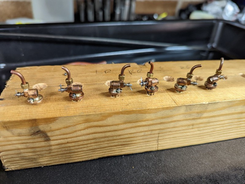 PXL_20221002_110717183 PXL_20221002_110717183 by Timothy Froud, on Flickr |
|
|
|
Post by Roger on Oct 2, 2022 20:34:00 GMT
The Return Crank Nut is an odd affair that appears to use a taper pin. That would be pretty tiny to scale, and I have a dislike for them, so I'm going to use a soft straight pin with one end upset slightly and the other slightly bent enough to stop it falling out. There's no real force trying to undo this, it just needs to not fall off. So here I'm cross drilling a 0.6mm hole through a 3mm Stainless Grub Screw which will be secured with Screw Lock in the Return Crank.  PXL_20221002_195723961 PXL_20221002_195723961 by Timothy Froud, on Flickr This is how the arrangement looks on 1501... 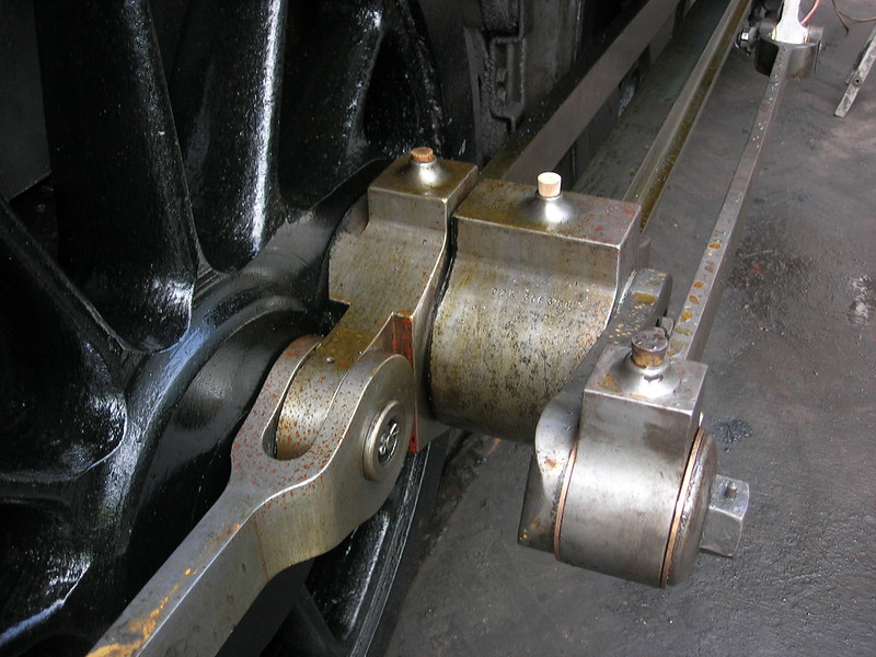 DSCN5641 DSCN5641 by Timothy Froud, on Flickr ... and my interpretation with the wire threaded through to get the thread in the right position.  PXL_20221002_201837723 PXL_20221002_201837723 by Timothy Froud, on Flickr Yet another little job ticked off the list. |
|
|
|
Post by Roger on Oct 5, 2022 18:28:38 GMT
This is what the Drain Cocks look like inside. The full sized ones use a poppet valve that's similar to the valve on an IC Engine. However, that's not easy to make and seal as one that uses a Silicon Nitride ball that's pushed off its seat by the shaft instead.  Sectioned drain cock Sectioned drain cock by Timothy Froud, on Flickr They're screwed into the Cylinder against an 'O' ring that's trapped on the OD and ID, so there's some compliance when it's screwed home. 'O' rings aren't supposed to be used that way, but it's a useful trick to allow for some adjustment while maintaining a seal. Three of the outer ones were ok, but for some reason I hadn't done the fourth one. So here that is having its flange thinned slightly so that it can turn round to the right place. It was about a quarter of a turn too tight, so that only needed 0.2mm to be removed. I'm holding it in my standard M5 threaded mount using a bolt and locknut at the back to make sure it doesn't wind onto the tool. The parting tool will easily get between the mount and the flange to make the adjustment. 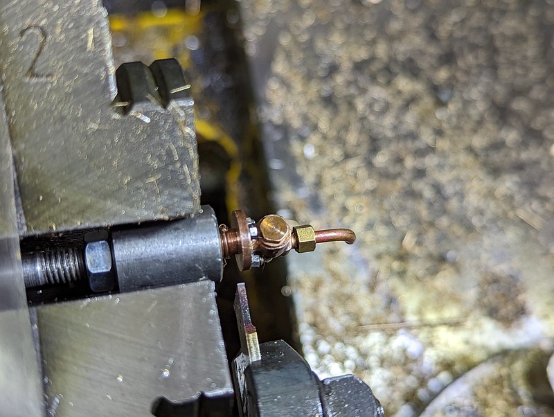 PXL_20221004_203655108 PXL_20221004_203655108 by Timothy Froud, on Flickr So far so good, now for the tricky bit ie getting the tiny mechanism assembled.  PXL_20221004_204854263 PXL_20221004_204854263 by Timothy Froud, on Flickr |
|


