|
|
Post by Roger on Dec 7, 2023 12:17:56 GMT
Looking better! You're getting there! I too was thinking about hobs and rack forms. Advantage perhaps being that the rack form having flat sides could be ground on HSS. The use of it to generate an involute would require coordinated passes of the tool above and below centreline plus rotation of the gear. Don't know how you'd do that on the machines you have hence referring to the free hobbing process often used for little gears. Perseverance will win in the end! It's almost there. I'm afraid hobbing anything but the full profile isn't possible. The tip of the 60 tooth cutter is just over 0.1mm wide. There's just no way you can make a tool any thinner than that and then use it to generate the tooth form. I'm just machining the 60tooth Form tool out of HSS, so soon I'll make the large gear again and hopefully this time they will mesh correctly. I'll give it a 60% chance this time. |
|
|
|
Post by Roger on Dec 8, 2023 21:10:50 GMT
I managed to break two 1mm cutters making this HSS Form Tool for the 60 tooth MOD 0.16mm gear, but got there in the end.  PXL_20231208_210116147 PXL_20231208_210116147 by Billy Roberts, on Flickr This time I've added a small boss on the face of the gear to contain it in the housing, because I've opted to use a plain 1mm shaft instead of trying to turn the ends down to 0.5mm  PXL_20231208_160748709 PXL_20231208_160748709 by Billy Roberts, on Flickr I've also added more holes for different sizes of wire so I can experiment with what's easiest to adjust. The intention is to adjust the Gain by using holes at a different radius to get the right deflection, and then adjust the zero point by bending the wire. I've got some soft Florist's wire that I used for the larger of the Split Pins, so that's one candidate. 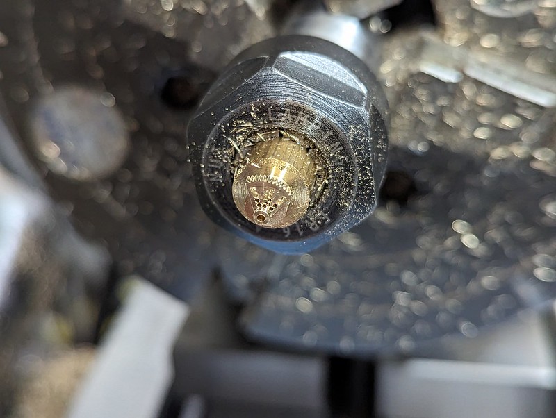 PXL_20231208_204544140 PXL_20231208_204544140 by Billy Roberts, on Flickr Anyway, these seem to mesh pretty nicely, but I'll have to mount them on proper shafts to make sure.  PXL_20231208_205743945 PXL_20231208_205743945 by Billy Roberts, on Flickr I'll probably end up making new gears anyway once the design is finalised, and maybe make a spare Gauge. 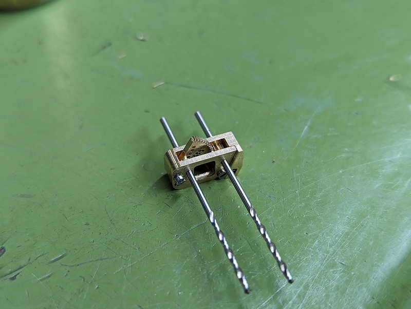 PXL_20231208_205801190 PXL_20231208_205801190 by Billy Roberts, on Flickr Once I'm happy with the gears, I can make the Phosphor Bronze inlet Union and get that Silver Soldered in place. |
|
|
|
Post by chris vine on Dec 8, 2023 23:05:25 GMT
Please use stainless wire so you can have the satisfaction of knowing that in a hundred years it will still work!!
C
|
|
|
|
Post by Roger on Dec 9, 2023 11:06:05 GMT
Please use stainless wire so you can have the satisfaction of knowing that in a hundred years it will still work!! C I'll see what I can so. |
|
|
|
Post by 92220 on Dec 9, 2023 11:23:08 GMT
Hi Roger.
That little "gearbox" looks superb!! An amazing bit of workmanship!!! You might find this ebay listing useful for stainless wire....eBay item number:165108275621 It is stainless steel piano wire in various diameters from 0.2mm up to 8mm, so you should be able to find a size to suit your gears.
Bob.
|
|
|
|
Post by Roger on Dec 9, 2023 16:34:12 GMT
Hi Roger. That little "gearbox" looks superb!! An amazing bit of workmanship!!! You might find this ebay listing useful for stainless wire....eBay item number:165108275621 It is stainless steel piano wire in various diameters from 0.2mm up to 8mm, so you should be able to find a size to suit your gears. Bob. Thanks Bob, I'll take a look. In the meantime, I've found some 1mm Hard Brass Wire, so I've just made the short shaft from that so I can move on. |
|
|
|
Post by Roger on Dec 9, 2023 21:07:13 GMT
I forgot to show you the details of the Pressure Gauge I'm making. You can see from this how the needle is pivoted really close to the bottom and there's a very large swing.  GWR Pressure Gauge GWR Pressure Gauge by Billy Roberts, on Flickr I've scaled the Pointer as closely as I can from the drawing, and I'm making it from Steel Shim so it can be Chemically Blacked. I'll have to spray a rust preventer onto it. I don't think it's practical to paint it, or make it from Stainless Steel for that reason. The Shim is 0.2mm thick, and the tip is only 0.24mm wide. The hole is 0.8mm and the OD at that point is 1.17mm I'm making several of them in the hope that at least one is usable. The Shim is stuck to the backing board with double sided tape, and I'm machining through the top clamping board in a long 2 degree spiralled entry, finishing with a full cut right around the Pointer. You have to cut this in one pass else it's going to move.  PXL_20231209_123528377 PXL_20231209_123528377 by Billy Roberts, on Flickr This is the centre boss, and it's the smallest thing I've ever made. The drill is 0.5mm diameter to match the end of the shaft. The body is 0.8mm diameter to fit through the Pointer. I'll probably secure that with permanent Loctite.  PXL_20231209_200225440 PXL_20231209_200225440 by Billy Roberts, on Flickr Here it is parted off, next to the big gear quadrant on its Brass Shaft and a 1mm drill.  PXL_20231209_200847652 PXL_20231209_200847652 by Billy Roberts, on Flickr Transferring that to the Pin Chuck was a challenge in itself, and here it is having the end faced off and a tiny chamfer added.  PXL_20231209_203738441 PXL_20231209_203738441 by Billy Roberts, on Flickr Quite how this will be attached to the shaft is yet to be decided. It really needs to be removable because the Dial will probably get in the way of setting it up. Maybe there's a low tack Loctite product I can use. I might try the 574 Flange Sealant, that's not very strong. How is this normally done? Do they go for a light press fit? That's pretty challenging, if they do. Anyway, one step at a time. 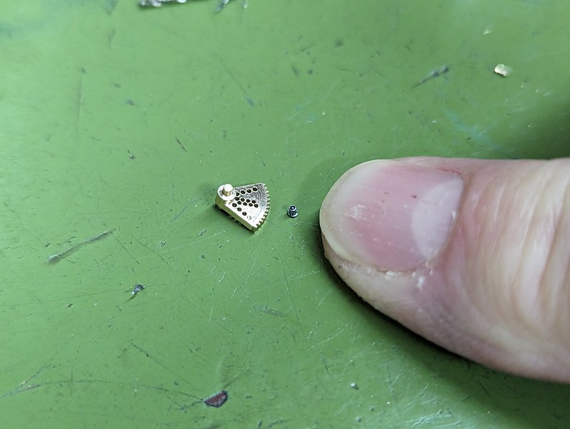 PXL_20231209_203928506 PXL_20231209_203928506 by Billy Roberts, on Flickr |
|
|
|
Post by 92220 on Dec 9, 2023 21:30:00 GMT
Those photos really show the quality and workmanship!!! Wow!!!
On the point about using steel shim for the pointer and slight concerns over rust prevention, why not use either brass or nickel silver to make the pointer? Both of these can be chemically blackened. You can even black anodise aluminium at home. There are a number or very impressive descriptions of how to home anodise, on the internet.
Bob.
|
|
|
|
Post by andyhigham on Dec 9, 2023 21:47:41 GMT
There is a process called black passivated zinc plate for steel, it leaves a very dark black/grey.
It's the process I had done on the frames of my NDM6
|
|
|
|
Post by Roger on Dec 10, 2023 11:30:54 GMT
Those photos really show the quality and workmanship!!! Wow!!! On the point about using steel shim for the pointer and slight concerns over rust prevention, why not use either brass or nickel silver to make the pointer? Both of these can be chemically blackened. You can even black anodise aluminium at home. There are a number or very impressive descriptions of how to home anodise, on the internet. Bob. Thanks for that Bob. I'll look into some of these options later. I've just made these in Steel for the moment. |
|
|
|
Post by Roger on Dec 10, 2023 11:32:24 GMT
There is a process called black passivated zinc plate for steel, it leaves a very dark black/grey. It's the process I had done on the frames of my NDM6 I've actually got the chemicals for doing this, I made a tumbler arrangement to try and plate tiny parts. However, it was proving a pain to get right, so I left it for another day. I'll pick it up and have another go at some point. |
|
|
|
Post by Roger on Dec 10, 2023 20:53:05 GMT
These are the Pressure Gauge Pointers, three being machined with 1.5mm PCB burrs, and three with a 3 flute Carbide End Mill. One of the PCB cut ones turned out to be ok, the others weren't any good. The PCB cut ones were far better, so that's what I'd use next time. I'd probably go in with a slightly steeper slope, say 3 degrees instead of the 2 degrees. I think it would cut through the sheet cleaner.  PXL_20231210_095614364 PXL_20231210_095614364 by Billy Roberts, on Flickr Anyway, after cleaning up with a Diamond Needle File, this is how that looked.  PXL_20231210_101450934 PXL_20231210_101450934 by Billy Roberts, on Flickr Fitting it onto the boss was a struggle, because the fit was a bit too close. In the end I drilled a hole in a piece of Brass and used that in the Lathe to push it on. 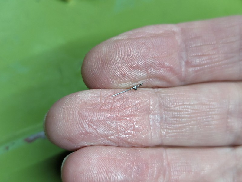 PXL_20231210_111145799 PXL_20231210_111145799 by Billy Roberts, on Flickr That was cleaned up with Acetone, and a blob of Locite 270 High Strength Threadlocker was used to lock it in place.  PXL_20231210_111157410 PXL_20231210_111157410 by Billy Roberts, on Flickr That was then chemically Blacked and dipped in preservative.  PXL_20231210_193113463 PXL_20231210_193113463 by Billy Roberts, on Flickr This is the Phosphor Bronze M2.6 union for a 1.6mm Swaged pipe.  PXL_20231210_122022202 PXL_20231210_122022202 by Billy Roberts, on Flickr That needed to be held by the thread to machine the back details, so this is a threaded mandrel with an M2.5 thread and a clearance so that the flange butts up against the face.  PXL_20231210_123542309 PXL_20231210_123542309 by Billy Roberts, on Flickr That was then faced off...  PXL_20231210_124325667 PXL_20231210_124325667 by Billy Roberts, on Flickr ... and the other details added. The Location is offset to one side, and the hole is offset in that so that it intersects with the hole from the Union.  PXL_20231210_151146415 PXL_20231210_151146415 by Billy Roberts, on Flickr A quick sanity check to make sure there was a hole all the way through.  PXL_20231210_193710130 PXL_20231210_193710130 by Billy Roberts, on Flickr This attaches to the bottom of the main body, overhanging the side. It's never going to stay that way while I Silver Solder it, so I'll make a fixture to hold that. If I make another one like this, I'll probably add a thin projection on the main body and perhaps make the flange slightly thinner. With a reasonable fillet of Silver Solder, it ought to be strong enough.  PXL_20231210_203323397 PXL_20231210_203323397 by Billy Roberts, on Flickr |
|
|
|
Post by Roger on Dec 11, 2023 21:55:00 GMT
Here's the Silver Soldering Fixture which has an M2.5 tapped hole in the end of a 4mm piece of Brass rod to hold the Union. You can just see the U shape of the thin Silver Solder wire, hooked over the fluxed flange. I've run out of Tippex, so I used the Black Felt Tip pen as a mask. 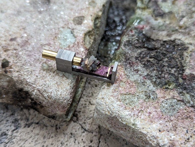 PXL_20231211_193103466 PXL_20231211_193103466 by Billy Roberts, on Flickr Fortunately, that seemed to work, and it's formed a nice fillet...  PXL_20231211_193235504 PXL_20231211_193235504 by Billy Roberts, on Flickr ... all the way round.  PXL_20231211_200716520 PXL_20231211_200716520 by Billy Roberts, on Flickr 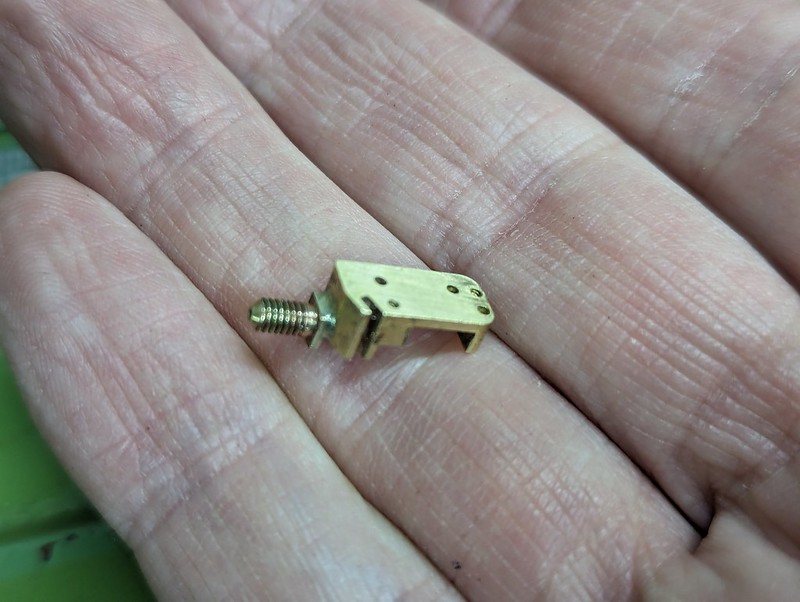 PXL_20231211_200728156 PXL_20231211_200728156 by Billy Roberts, on Flickr The Body of the Gauge is just a simple turning job with a slot for the Steam connection and the various fixing holes.  PXL_20231211_204814611 PXL_20231211_204814611 by Billy Roberts, on Flickr I've had to reduce the size of the Silver Solder fillet because it was preventing the parts sitting together correctly. Other than that, it seems to be ok.  PXL_20231211_214158443 PXL_20231211_214158443 by Billy Roberts, on Flickr |
|
|
|
Post by terrier060 on Dec 11, 2023 22:21:58 GMT
I have just watched the film LONGITUDE again and I thought of you! I am sure making a sea clock was easier than your watchmaking. Very ingenious. How many jewels!?
Ed
|
|
jma1009
Elder Statesman
  
Posts: 5,919
|
Post by jma1009 on Dec 12, 2023 1:23:46 GMT
I am a bit bemused by the use of gears as Freddie Dinnis never used them. I know Roy Amesbury did, or at least that is what he described, but I’ve never examined a Roy Amesbury miniature pressure gauge - whereas I have examined a number of Freddie Dinnis gauges plus was invited to his home in Ward Avenue Cowes and saw some of his kit, and others such as Peter Craddock and Ron Shephard filled in a few details.
Anyway, when gearing you have to be cognisant with clock type teething and depth tooling in this sort of situation.
What I do remember is Freddie showing his vacuum gauges that had drawn phos bronze tubing of less thickness. In theory, they ought (to my mind anyway) ought to suggest an absence of gears for the perhaps extended deflection Roger is aiming at to replicate a scale GWR miniature pressure gauge.
Actually, Freddie’s gauges did have the sort of proportions on the dial that Roger is aiming at, with a long graduation and arc, and the pivot point of the needle being lower than that on mass produced products.
Freddie had his needles press stamped out in brass in a miniature fly press with the tooling.
He must have rolled the bourdon tube like Roger has done rather than what I was told at the time, and this would have work hardened the tube after the annealed drawing process.
|
|
|
|
Post by Roger on Dec 12, 2023 9:37:26 GMT
I have just watched the film LONGITUDE again and I thought of you! I am sure making a sea clock was easier than your watchmaking. Very ingenious. How many jewels!? Ed Hi Ed, Sadly I'm not in the same league as those amazing pioneers. Fortunately wear isn't an issue with a Pressure Gauge, so no jewels! |
|
|
|
Post by Roger on Dec 12, 2023 9:44:46 GMT
I am a bit bemused by the use of gears as Freddie Dinnis never used them. I know Roy Amesbury did, or at least that is what he described, but I’ve never examined a Roy Amesbury miniature pressure gauge - whereas I have examined a number of Freddie Dinnis gauges plus was invited to his home in Ward Avenue Cowes and saw some of his kit, and others such as Peter Craddock and Ron Shephard filled in a few details. Anyway, when gearing you have to be cognisant with clock type teething and depth tooling in this sort of situation. What I do remember is Freddie showing his vacuum gauges that had drawn phos bronze tubing of less thickness. In theory, they ought (to my mind anyway) ought to suggest an absence of gears for the perhaps extended deflection Roger is aiming at to replicate a scale GWR miniature pressure gauge. Actually, Freddie’s gauges did have the sort of proportions on the dial that Roger is aiming at, with a long graduation and arc, and the pivot point of the needle being lower than that on mass produced products. Freddie had his needles press stamped out in brass in a miniature fly press with the tooling. He must have rolled the bourdon tube like Roger has done rather than what I was told at the time, and this would have work hardened the tube after the annealed drawing process. Hi Julian, You certainly don't need gears to get a lot of travel, but there are issues with linearity if you're using levers alone. There are quite a few options with regard to the layout, I've just copied one that I've seen that I thought I could make and would give the required result. I'm certainly not advocating that this is the best design or that anyone should try to replicate what I'm doing. I rarely take the easiest solution, preferring to do what I find the most satisfying. |
|
|
|
Post by Roger on Dec 13, 2023 22:24:32 GMT
Here are are the component parts for making two Bourdon Tubes. The 9mm x 26mm x 0.05mm Beryllium Copper blanks, Titanium Strips for forming and Silver Soldering and the Shims for forming the finished item.  PXL_20231213_110211132 PXL_20231213_110211132 by Billy Roberts, on Flickr This is the same method as before, but the material is 50 instead of 80 microns and 3.5mm finished ID compared to 4.2mm with the thicker material. This just holds it so that it can be passed to the Vise.  PXL_20231213_111528053 PXL_20231213_111528053 by Billy Roberts, on Flickr The Square section former doesn't get it very close to 90 degrees, so here's a triangular former to get it further...  PXL_20231213_112916883 PXL_20231213_112916883 by Billy Roberts, on Flickr ... like this... 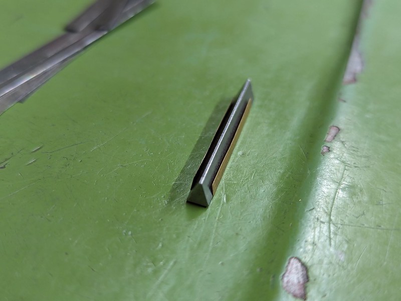 PXL_20231213_112516611 PXL_20231213_112516611 by Billy Roberts, on Flickr ... before completely folding it over.  PXL_20231213_115043458 PXL_20231213_115043458 by Billy Roberts, on Flickr A thin wire of Silver Solder is buried under the Flux...  PXL_20231213_120611241 PXL_20231213_120611241 by Billy Roberts, on Flickr ... but only one took well. 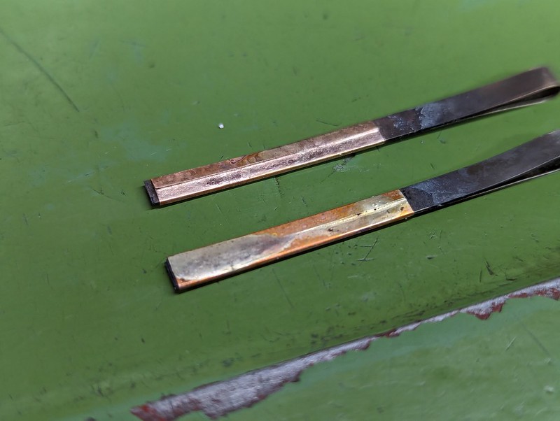 PXL_20231213_165103729 PXL_20231213_165103729 by Billy Roberts, on Flickr Working with the better one, here's the adjusted forming roller that produces the required 11.6mm finished OD. There are 4 thin shims inside... 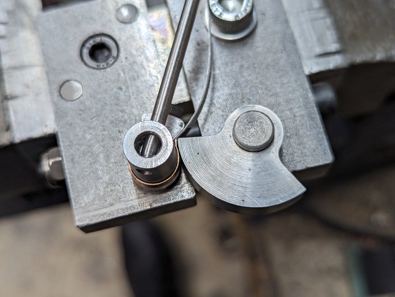 PXL_20231213_173148121 PXL_20231213_173148121 by Billy Roberts, on Flickr ... which slightly foul the clamp and have to be finished manually. I'm actually rather surprised at how easy it is to make Bourdon Tubes this way. However, it's too soon to make a final judgement, since i don't have a working gauge yet!  PXL_20231213_173459627 PXL_20231213_173459627 by Billy Roberts, on Flickr This still needs a little tidying up, but it's possibly Steam tight. 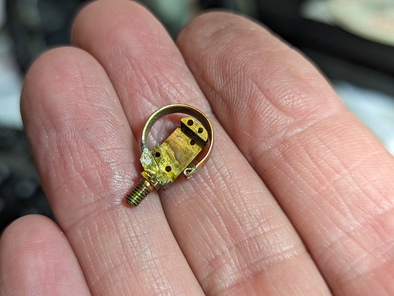 PXL_20231213_215246655 PXL_20231213_215246655 by Billy Roberts, on Flickr The wire attachment is a 0.025mm piece of Copper shim, folded around a 0.5mm wire and trimmed to fit the open end of the Boudron Tube. That was Soft Soldered before attaching it to the body.  PXL_20231213_215300421 PXL_20231213_215300421 by Billy Roberts, on Flickr The next step is to connect this up to the Compressed Air supply to see if it's got any leaks and to see what sort of travel it's going to give. |
|
|
|
Post by Roger on Dec 14, 2023 21:26:42 GMT
I decided to use Phosphor Bronze for the main shaft because I had some 4mm material and it's strong and easy enough to machine. Here it is with the small gear being bonded on with Loctite 270 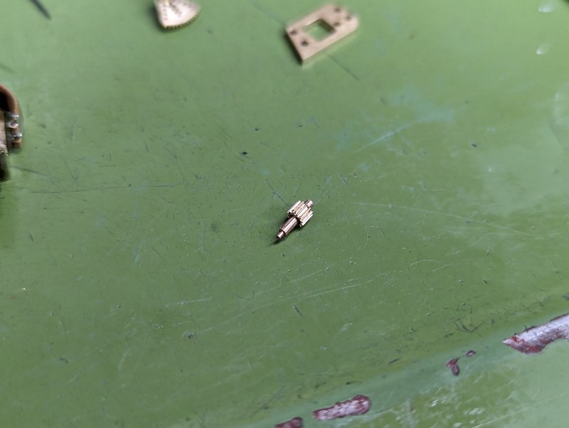 PXL_20231214_211920537 PXL_20231214_211920537 by Billy Roberts, on Flickr |
|
|
|
Post by chris vine on Dec 14, 2023 23:11:09 GMT
And for Roger's next project: A coal fired 00 Gauge live steam loco...
Chris.
|
|